DODGE RAM SRT-10 2006 Service Repair Manual
Manufacturer: DODGE, Model Year: 2006, Model line: RAM SRT-10, Model: DODGE RAM SRT-10 2006Pages: 5267, PDF Size: 68.7 MB
Page 3501 of 5267
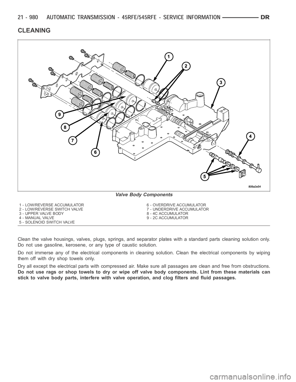
CLEANING
Clean the valve housings, valves, plugs, springs, and separator plates with a standard parts cleaning solution only.
Do not use gasoline, kerosene, or any type of caustic solution.
Do not immerse any of the electrical components in cleaning solution. Clean the electrical components by wiping
them off with dry shop towels only.
Dry all except the electrical parts with compressed air. Make sure all passages are clean and free from obstructions.
Do not use rags or shop towels to dry or wipe off valve body components. Lint from these materials can
stick to valve body parts, interfere with valve operation, and clog filters and fluid passages.
Valve Body Components
1 - LOW/REVERSE ACCUMULATOR 6 - OVERDRIVE ACCUMULATOR
2 - LOW/REVERSE SWITCH VALVE 7 - UNDERDRIVE ACCUMULATOR
3 - UPPER VALVE BODY 8 - 4C ACCUMULATOR
4 - MANUAL VALVE 9 - 2C ACCUMULATOR
5 - SOLENOID SWITCH VALVE
Page 3502 of 5267
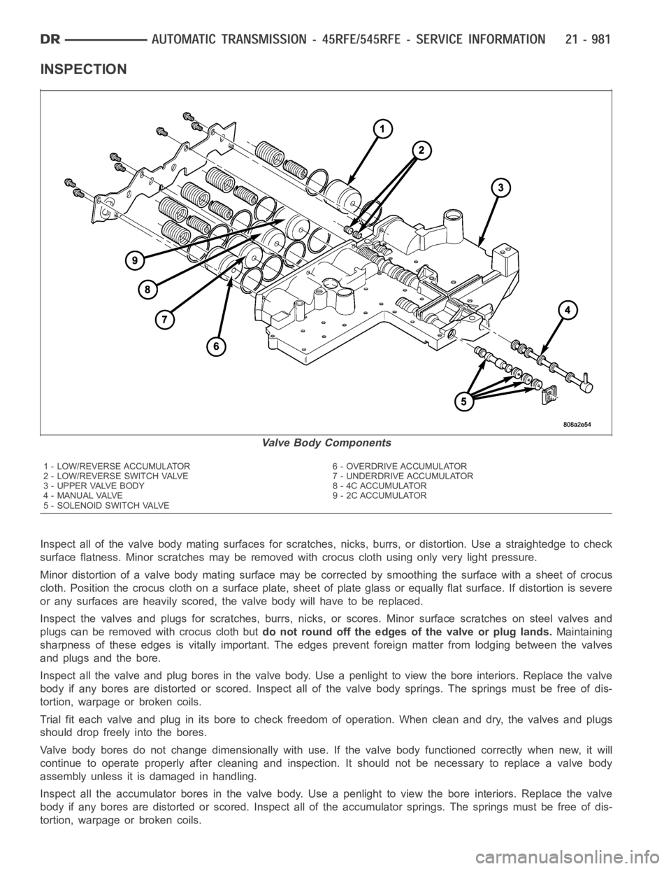
INSPECTION
Inspect all of the valve body mating surfaces for scratches, nicks, burrs,or distortion. Use a straightedge to check
surface flatness. Minor scratches may be removed with crocus cloth using only very light pressure.
Minor distortion of a valve body mating surface may be corrected by smoothing the surface with a sheet of crocus
cloth. Position the crocus cloth on a surface plate, sheet of plate glass orequally flat surface. If distortion is severe
or any surfaces are heavily scored, the valve body will have to be replaced.
Inspect the valves and plugs for scratches, burrs, nicks, or scores. Minorsurface scratches on steel valves and
plugs can be removed with crocus cloth butdo not round off the edges of the valve or plug lands.Maintaining
sharpness of these edges is vitally important. The edges prevent foreign matter from lodging between the valves
and plugs and the bore.
Inspect all the valve and plug bores in the valve body. Use a penlight to viewthe bore interiors. Replace the valve
body if any bores are distorted or scored. Inspect all of the valve body springs. The springs must be free of dis-
tortion, warpage or broken coils.
Trial fit each valve and plug in its bore to check freedom of operation. Whenclean and dry, the valves and plugs
shoulddropfreelyintothebores.
Valve body bores do not change dimensionally with use. If the valve body functioned correctly when new, it will
continue to operate properly after cleaning and inspection. It should notbe necessary to replace a valve body
assembly unless it is damaged in handling.
Inspect all the accumulator bores in the valve body. Use a penlight to view the bore interiors. Replace the valve
body if any bores are distorted or scored. Inspect all of the accumulator springs. The springs must be free of dis-
tortion, warpage or broken coils.
Valve Body Components
1 - LOW/REVERSE ACCUMULATOR 6 - OVERDRIVE ACCUMULATOR
2 - LOW/REVERSE SWITCH VALVE 7 - UNDERDRIVE ACCUMULATOR
3 - UPPER VALVE BODY 8 - 4C ACCUMULATOR
4 - MANUAL VALVE 9 - 2C ACCUMULATOR
5 - SOLENOID SWITCH VALVE
Page 3503 of 5267

Inspect all the fluid seals on the valve body. Replace
any seals that are cracked, distorted, or damaged in
any way. These seals pass fluid pressure directly to
the clutches. Any pressure leak at these points, may
cause transmission performance problems.
Page 3504 of 5267
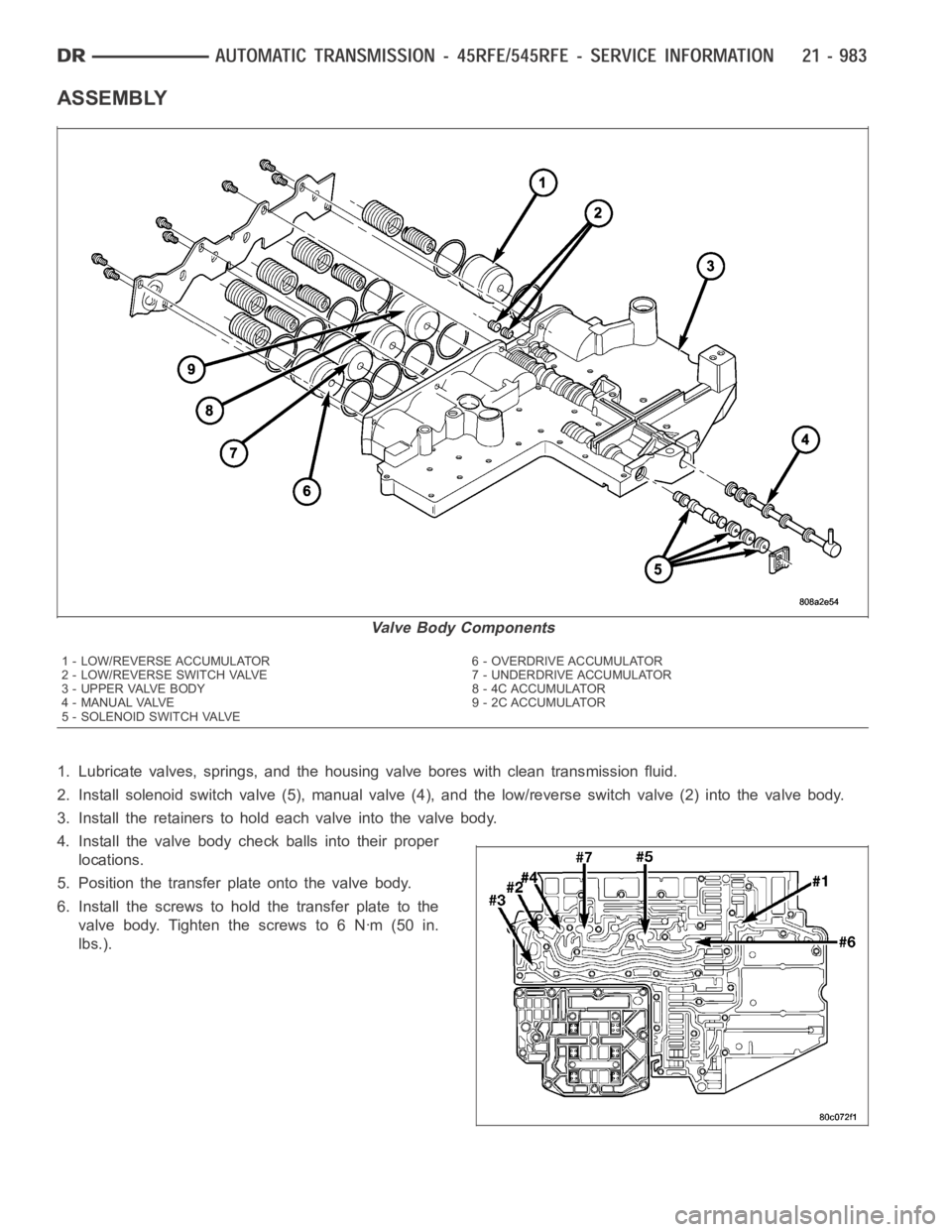
ASSEMBLY
1. Lubricate valves, springs, and the housing valve bores with clean transmission fluid.
2. Install solenoid switch valve (5), manual valve (4), and the low/reverseswitchvalve(2)intothevalvebody.
3. Install the retainers to hold each valve into the valve body.
4. Install the valve body check balls into their proper
locations.
5. Position the transfer plate onto the valve body.
6. Install the screws to hold the transfer plate to the
valve body. Tighten the screws to 6 Nꞏm (50 in.
lbs.).
Valve Body Components
1 - LOW/REVERSE ACCUMULATOR 6 - OVERDRIVE ACCUMULATOR
2 - LOW/REVERSE SWITCH VALVE 7 - UNDERDRIVE ACCUMULATOR
3 - UPPER VALVE BODY 8 - 4C ACCUMULATOR
4 - MANUAL VALVE 9 - 2C ACCUMULATOR
5 - SOLENOID SWITCH VALVE
Page 3505 of 5267
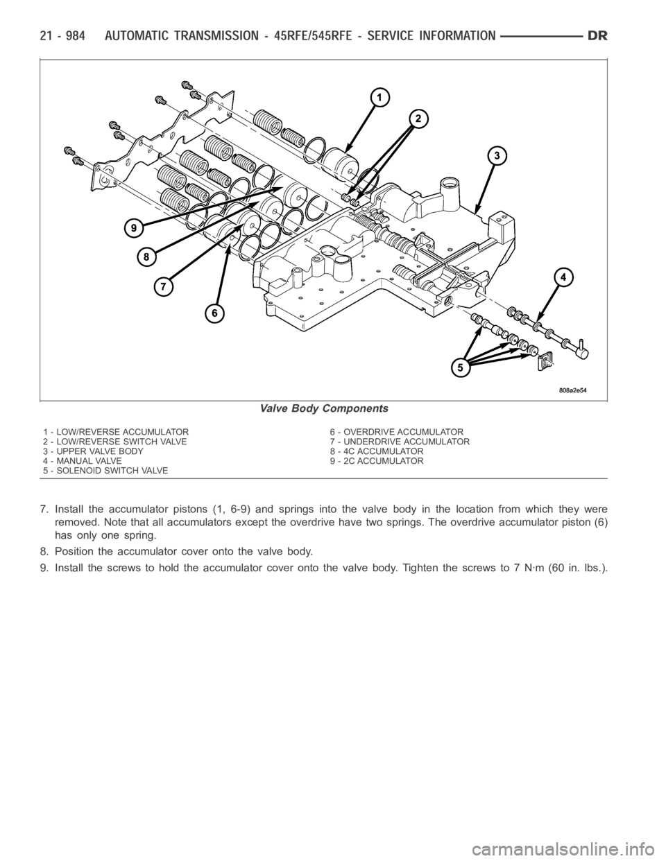
7. Install the accumulator pistons (1, 6-9) and springs into the valve bodyin the location from which they were
removed. Note that all accumulators except the overdrive have two springs. The overdrive accumulator piston (6)
has only one spring.
8. Position the accumulator cover onto the valve body.
9. Install the screws to hold the accumulator cover onto the valve body. Tighten the screws to 7 Nꞏm (60 in. lbs.).
Valve Body Components
1 - LOW/REVERSE ACCUMULATOR 6 - OVERDRIVE ACCUMULATOR
2 - LOW/REVERSE SWITCH VALVE 7 - UNDERDRIVE ACCUMULATOR
3 - UPPER VALVE BODY 8 - 4C ACCUMULATOR
4 - MANUAL VALVE 9 - 2C ACCUMULATOR
5 - SOLENOID SWITCH VALVE
Page 3506 of 5267
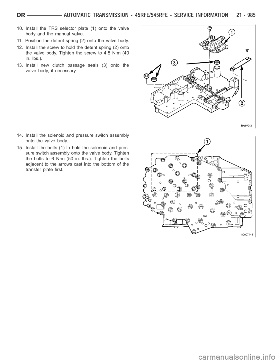
10. Install the TRS selector plate (1) onto the valve
body and the manual valve.
11. Position the detent spring (2) onto the valve body.
12. Install the screw to hold the detent spring (2) onto
the valve body. Tighten the screw to 4.5 Nꞏm (40
in. lbs.).
13. Install new clutch passage seals (3) onto the
valve body, if necessary.
14. Install the solenoid and pressure switch assembly
onto the valve body.
15. Install the bolts (1) to hold the solenoid and pres-
sure switch assembly onto the valve body. Tighten
the bolts to 6 Nꞏm (50 in. lbs.). Tighten the bolts
adjacent to the arrows cast into the bottom of the
transfer plate first.
Page 3507 of 5267
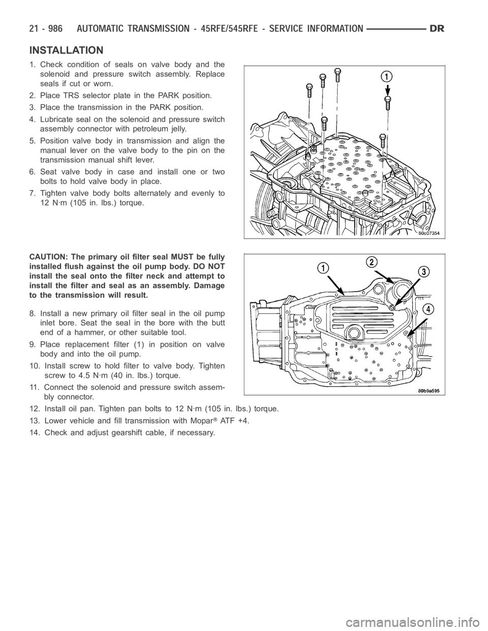
INSTALLATION
1. Check condition of seals on valve body and the
solenoid and pressure switch assembly. Replace
seals if cut or worn.
2. Place TRS selector plate in the PARK position.
3. Place the transmission in the PARK position.
4. Lubricate seal on the solenoid and pressure switch
assembly connector with petroleum jelly.
5. Position valve body in transmission and align the
manual lever on the valve body to the pin on the
transmission manual shift lever.
6. Seat valve body in case and install one or two
bolts to hold valve body in place.
7. Tighten valve body bolts alternately and evenly to
12 Nꞏm (105 in. lbs.) torque.
CAUTION: The primary oil filter seal MUST be fully
installed flush against the oil pump body. DO NOT
install the seal onto the filter neck and attempt to
install the filter and seal as an assembly. Damage
to the transmission will result.
8. Install a new primary oil filter seal in the oil pump
inlet bore. Seat the seal in the bore with the butt
end of a hammer, or other suitable tool.
9. Place replacement filter (1) in position on valve
body and into the oil pump.
10. Install screw to hold filter to valve body. Tighten
screw to 4.5 Nꞏm (40 in. lbs.) torque.
11. Connect the solenoid and pressure switch assem-
bly connector.
12. Install oil pan. Tighten pan bolts to 12 Nꞏm (105 in. lbs.) torque.
13. Lower vehicle and fill transmission with Mopar
AT F + 4 .
14. Check and adjust gearshift cable, if necessary.
Page 3508 of 5267
page page
AUTOMATIC TRANSMISSION - 48RE - GAS -
ELECTRICAL DIAGNOSTICS
DIAGNOSIS AND TESTING
P0711-TRANS TEMP SENSOR, NO TEMP
RISE AFTER START (GAS)................. 989
P0712-TRANS TEMP SENSOR VOLTAGE
TOO LOW (GAS)........................... 993
P0713-TRANS TEMP SENSOR VOLTAGE
TOO HIGH (GAS).......................... 999
P0720-LOW OUTPUT SPEED SENSOR -
RPM ABOVE 15 MPH (GAS)............... 1007
P0740-TORQ CON CLU, NO RPM DROP AT
LOCKUP (GAS)........................... 1013
P0743-TORQUE CONVERTER CLUTCH
SOLENOID/TRANS RELAY CIRCUITS. ..... 1017
P0748-PRESSURE SOL CONTROL/TRANS
RELAY CIRCUITS (GAS)................... 1024
P0751-O/D SWITCH PRESSED (LO) MORE
THAN 5 MINUTES........................ 1031
P0753-TRANS 3-4 SHIFT SOL/TRANS
RELAY CIRCUITS (GAS)................... 1034
P0783-3-4 SHIFT SOL, NO RPM DROP AT
LOCKUP (GAS)........................... 1041
P0850-P/N SWITCH PERFORMANCE
(GAS).................................... 1045
P128B-TCM POWER CONTROL CIRCUIT 2
LOW - TIPM.............................. 1050P128C-TCM POWER CONTROL CIRCUIT 2
HIGH - TIPM.............................. 1053
P128D-TCM POWER CONTROL CIRCUIT 2
OPEN - TIPM............................. 1056
P128E-TCM POWER CONTROL CIRCUIT 2
OVERCURRENT - TIPM................... 1059
P1740-TCC O/D SOL PERFORMANCE
(GAS).................................... 1063
P1756-GOV PRESS NOT EQUAL TO
TARGET @ 35 - 40 PSI (GAS)............. 1068
P1757-GOV PRESS ABOVE 3 PSI IN GEAR
WITH 0 MPH (GAS)....................... 1075
P1762-GOV PRESS SENSOR OFFSET
VOLTS TOO LOW OR HIGH (GAS)......... 1081
P1763-GOVERNOR PRESSURE SENSOR
VOLTS TOO HI (GAS)..................... 1087
P1764-GOVERNOR PRESSURE SENSOR
VOLTS TOO LOW (GAS)................... 1094
P1765-TRANS 12 VOLT SUPPLY RELAY
CTRL CIRCUIT (GAS)..................... 1099
STANDARD PROCEDURE
PRE-DIAGNOSTIC TROUBLE SHOOTING
PROCEDURE - 48RE GAS................. 1103
TRANSMISSION VERIFICATION TEST VER -
1(GAS).................................. 1104
Page 3509 of 5267

AUTOMATIC TRANSMISSION - 48RE - GAS - ELECTRICAL
DIAGNOSTICS
DIAGNOSIS AND TESTING
Page 3510 of 5267

P0711-TRANS TEMP SENSOR, NO TEMP RISE AFTER START (GAS)
For a complete wiring diagramRefer to Section 8W.