DODGE RAM SRT-10 2006 Service Repair Manual
Manufacturer: DODGE, Model Year: 2006, Model line: RAM SRT-10, Model: DODGE RAM SRT-10 2006Pages: 5267, PDF Size: 68.7 MB
Page 3941 of 5267
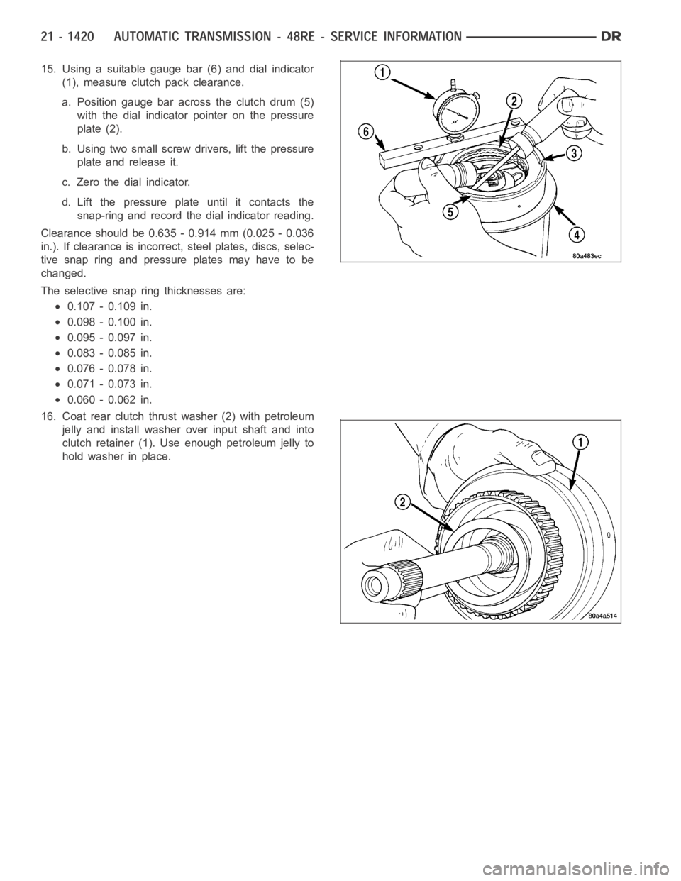
15. Using a suitable gauge bar (6) and dial indicator
(1), measure clutch pack clearance.
a. Position gauge bar across the clutch drum (5)
with the dial indicator pointer on the pressure
plate (2).
b. Using two small screw drivers, lift the pressure
plate and release it.
c. Zero the dial indicator.
d. Lift the pressure plate until it contacts the
snap-ring and record the dial indicator reading.
Clearance should be 0.635 - 0.914 mm (0.025 - 0.036
in.). If clearance is incorrect, steel plates, discs, selec-
tive snap ring and pressure plates may have to be
changed.
The selective snap ring thicknesses are:
0.107 - 0.109 in.
0.098 - 0.100 in.
0.095 - 0.097 in.
0.083 - 0.085 in.
0.076 - 0.078 in.
0.071 - 0.073 in.
0.060 - 0.062 in.
16. Coat rear clutch thrust washer (2) with petroleum
jelly and install washer over input shaft and into
clutch retainer (1). Use enough petroleum jelly to
hold washer in place.
Page 3942 of 5267
SERVO-REAR
DESCRIPTION
The rear (low/reverse) servo consists of a single stage or diameter pistonand a spring loaded plug. The spring is
used to cushion the application of the rear (low/reverse) band.
OPERATION
While in the de-energized state (no pressure applied), the piston is held up in its bore by the piston spring. The plug
is held down in its bore, in the piston, by the plug spring. When pressure is applied to the top of the piston, the plug
is forced down in its bore, taking up any clearance. As the piston moves, it causes the plug spring to compress, and
the piston moves down over the plug. The piston continues to move down untilit hits the shoulder of the plug and
fully applies the band. The period of time from the initial application, until the piston is against the shoulder of the
plug, represents a reduced shocking of the band that cushions the shift.
DISASSEMBLY
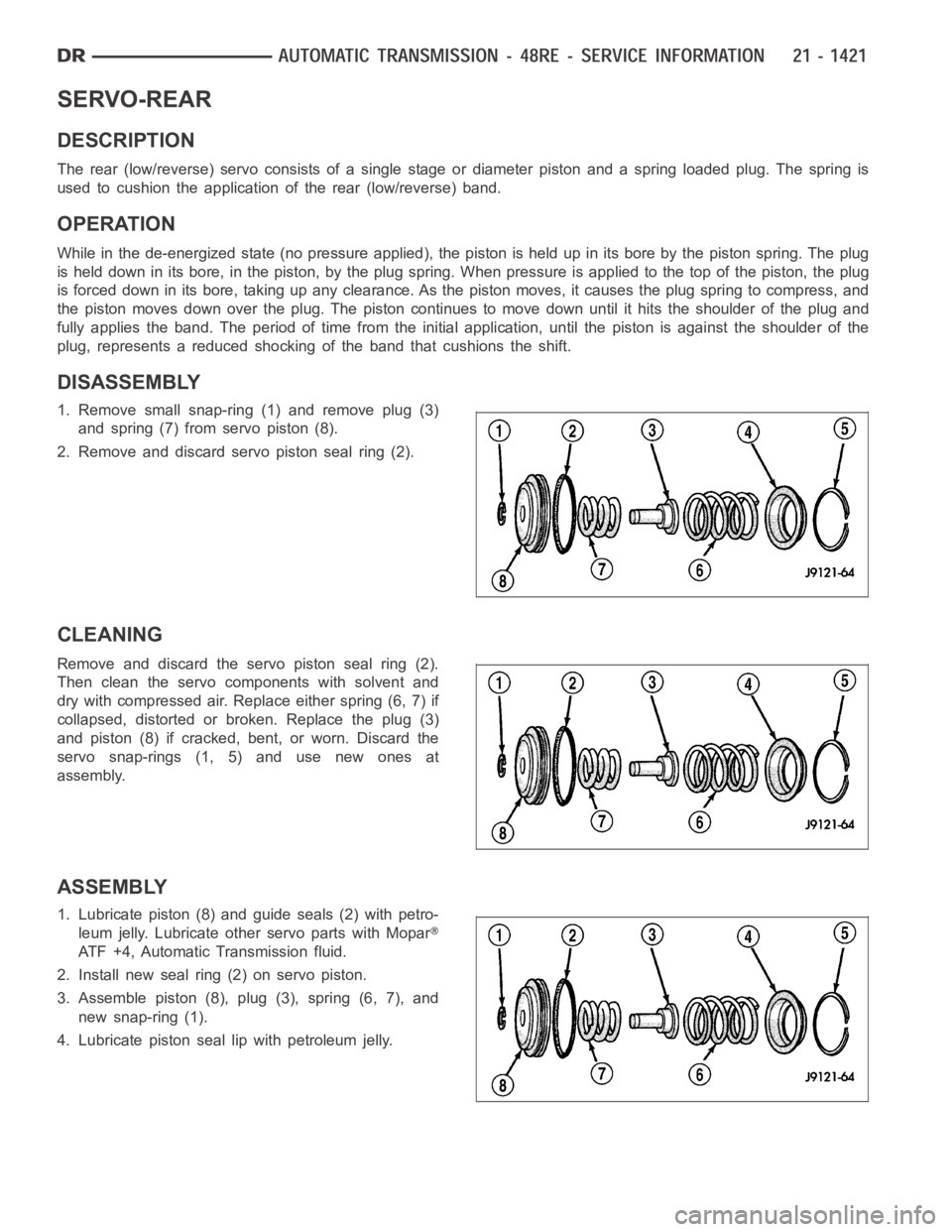
1. Remove small snap-ring (1) and remove plug (3)
and spring (7) from servo piston (8).
2. Remove and discard servo piston seal ring (2).
CLEANING
Remove and discard the servo piston seal ring (2).
Then clean the servo components with solvent and
dry with compressed air. Replace either spring (6, 7) if
collapsed, distorted or broken. Replace the plug (3)
and piston (8) if cracked, bent, or worn. Discard the
servo snap-rings (1, 5) and use new ones at
assembly.
ASSEMBLY
1. Lubricate piston (8) and guide seals (2) with petro-
leum jelly. Lubricate other servo parts with Mopar
ATF +4, Automatic Transmission fluid.
2. Install new seal ring (2) on servo piston.
3. Assemble piston (8), plug (3), spring (6, 7), and
new snap-ring (1).
4. Lubricate piston seal lip with petroleum jelly.
Page 3943 of 5267
MECHANISM-SHIFT
DESCRIPTION
The gear shift mechanism provides six shift positions which are:
PA R K ( P )
REVERSE (R)
NEUTRAL (N)
DRIVE (D)
Manual SECOND (2)
Manual LOW (1)
OPERATION
Manual LOW (1) range provides first gear only. Overrun braking is also provided in this range. Manual SECOND (2)
range provides first and second gear only.
DRIVE range provides first, second, third, and overdrive fourth gear ranges. The shift into overdrive fourth gear
range occurs only after the transmission has completed the shift into D third gear range. No further movement of the
shift mechanism is required to complete the 3-4 shift.
The fourth gear upshift occurs automatically when the overdrive selectorswitch is in the ON position. No upshift to
fourth gear will occur if any of the following are true:
The transmission fluid temperature is below 10° C (50° F) or above 121° C (250° F).
The shift to third is not yet complete.
Vehicle speed is too low for the 3-4 shift to occur.
Battery temperature is below -5° C (23° F).
Page 3944 of 5267
SENSOR-SPEED
DESCRIPTION
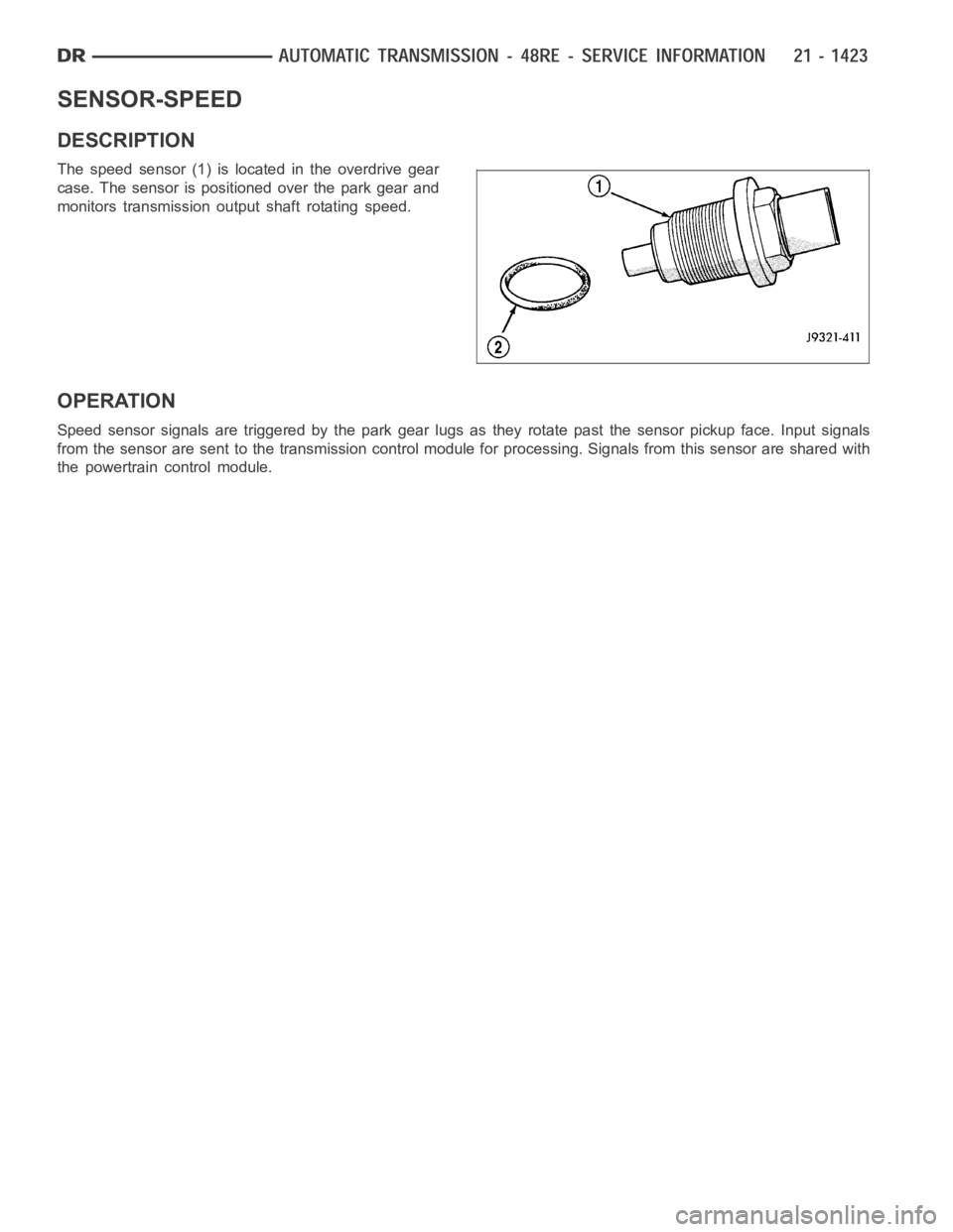
The speed sensor (1) is located in the overdrive gear
case. The sensor is positioned over the park gear and
monitors transmission output shaft rotating speed.
OPERATION
Speed sensor signals are triggered by the park gear lugs as they rotate pastthe sensor pickup face. Input signals
from the sensor are sent to the transmission control module for processing. Signals from this sensor are shared with
the powertrain control module.
Page 3945 of 5267
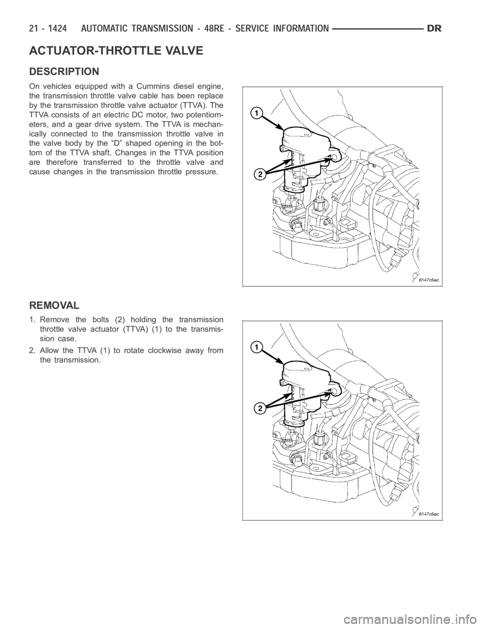
ACTUATOR-THROTTLE VALVE
DESCRIPTION
On vehicles equipped with a Cummins diesel engine,
the transmission throttle valve cable has been replace
by the transmission throttle valve actuator (TTVA). The
TTVA consists of an electric DC motor, two potentiom-
eters, and a gear drive system. The TTVA is mechan-
ically connected to the transmission throttle valve in
the valve body by the “D” shaped opening in the bot-
tom of the TTVA shaft. Changes in the TTVA position
are therefore transferred to the throttle valve and
cause changes in the transmission throttle pressure.
REMOVAL
1. Remove the bolts (2) holding the transmission
throttle valve actuator (TTVA) (1) to the transmis-
sion case.
2. Allow the TTVA (1) to rotate clockwise away from
the transmission.
Page 3946 of 5267
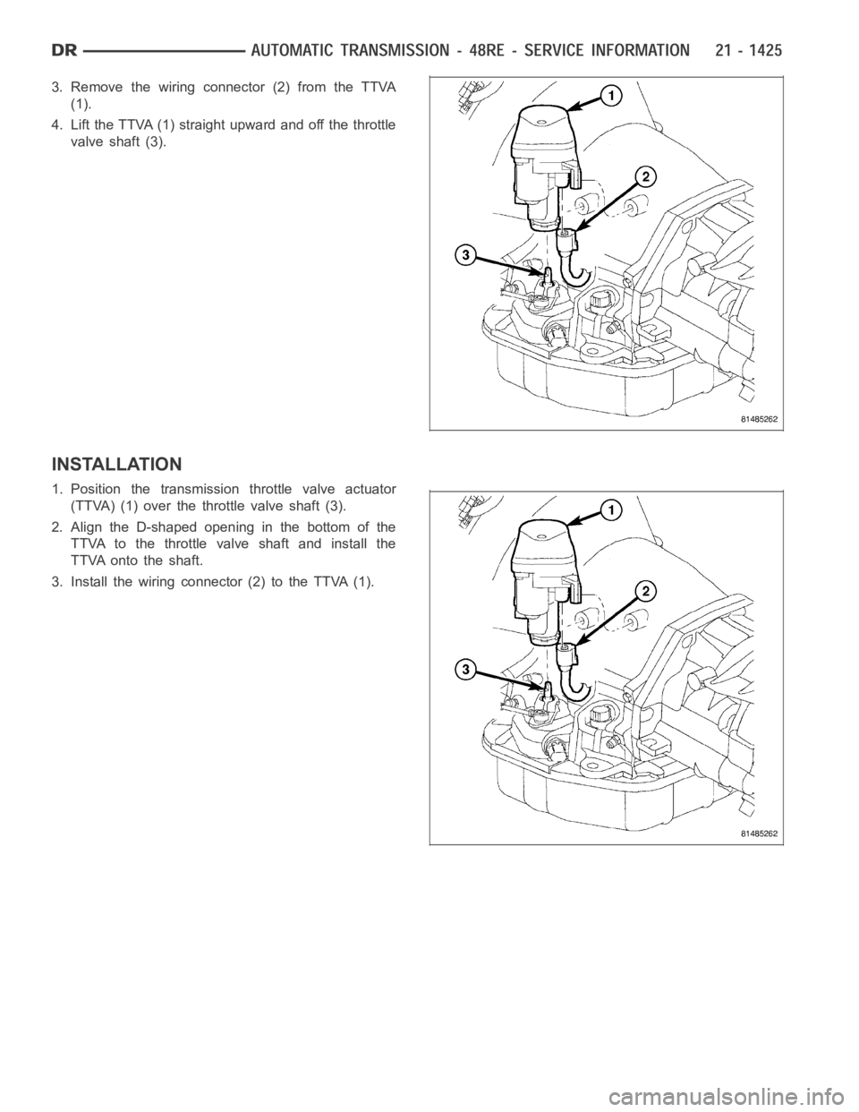
3. Remove the wiring connector (2) from the TTVA
(1).
4. Lift the TTVA (1) straight upward and off the throttle
valve shaft (3).
INSTALLATION
1. Position the transmission throttle valve actuator
(TTVA) (1) over the throttle valve shaft (3).
2. Align the D-shaped opening in the bottom of the
TTVA to the throttle valve shaft and install the
TTVA onto the shaft.
3. Install the wiring connector (2) to the TTVA (1).
Page 3947 of 5267
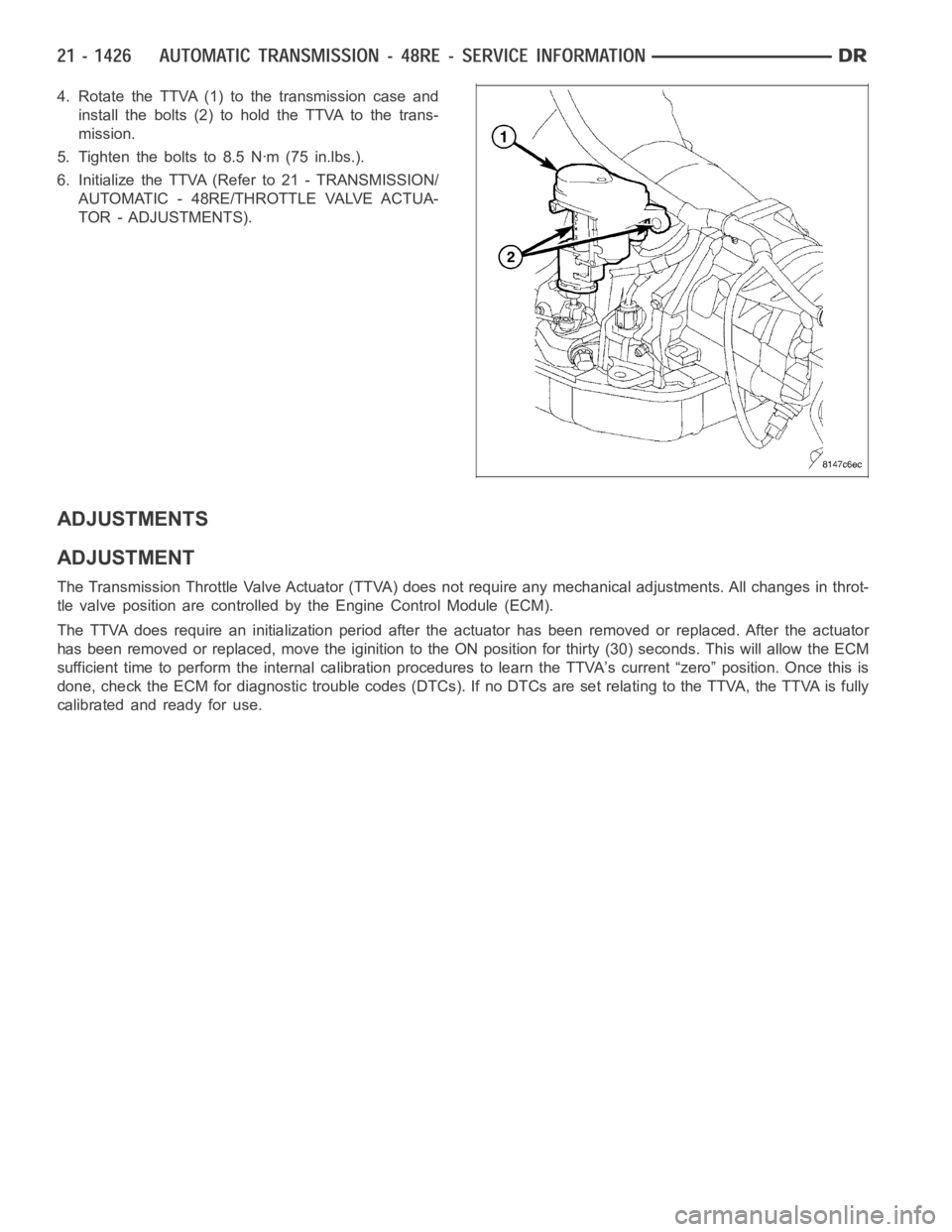
4. Rotate the TTVA (1) to the transmission case and
install the bolts (2) to hold the TTVA to the trans-
mission.
5. Tighten the bolts to 8.5 Nꞏm (75 in.lbs.).
6. Initialize the TTVA (Refer to 21 - TRANSMISSION/
AUTOMATIC - 48RE/THROTTLE VALVE ACTUA-
TOR - ADJUSTMENTS).
ADJUSTMENTS
ADJUSTMENT
The Transmission Throttle Valve Actuator (TTVA) does not require any mechanical adjustments. All changes in throt-
tle valve position are controlled by the Engine Control Module (ECM).
The TTVA does require an initialization period after the actuator has beenremoved or replaced. After the actuator
has been removed or replaced, move the iginition to the ON position for thirty (30) seconds. This will allow the ECM
sufficient time to perform the internal calibration procedures to learn the TTVA’s current “zero” position. Once this is
done, check the ECM for diagnostic trouble codes (DTCs). If no DTCs are set relating to the TTVA, the TTVA is fully
calibrated and ready for use.
Page 3948 of 5267
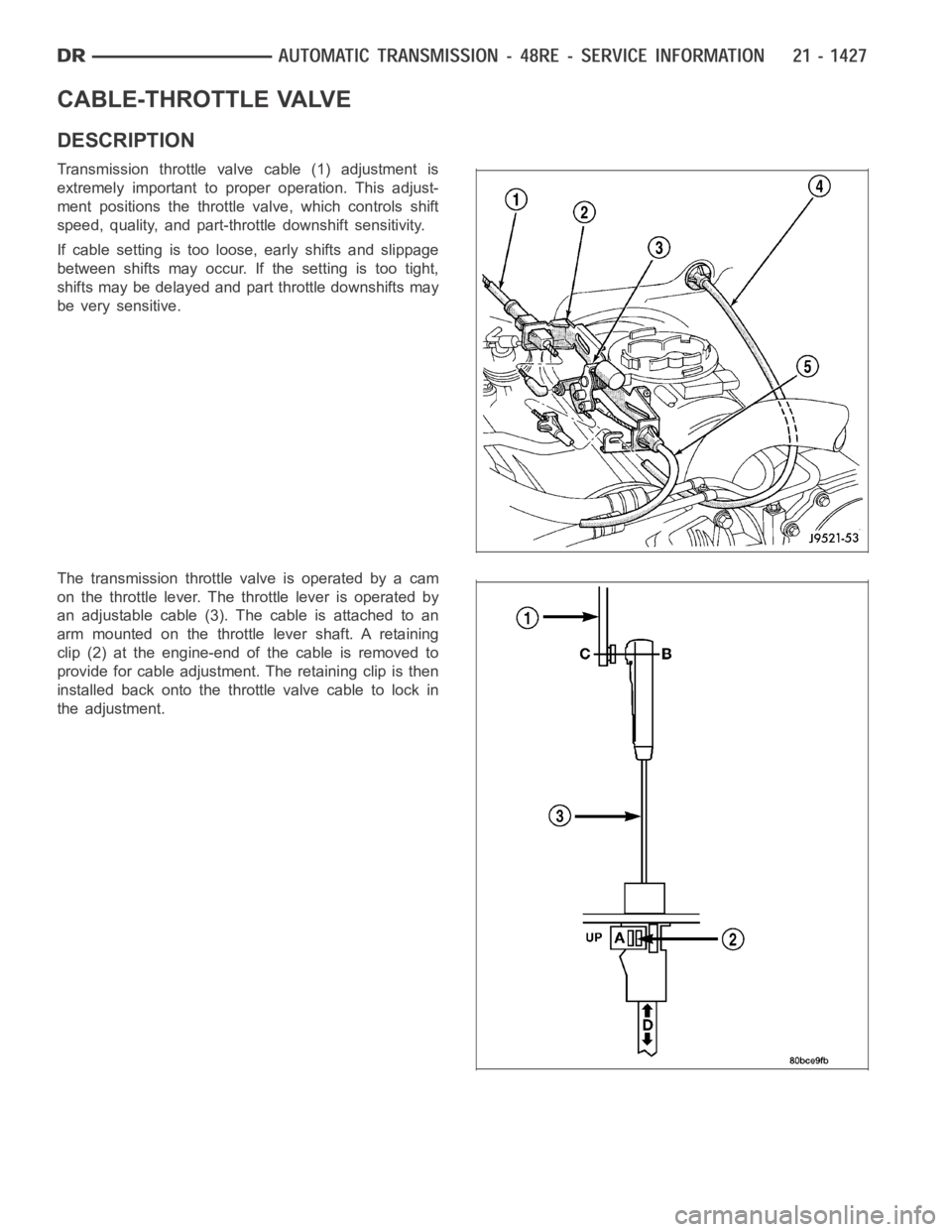
CABLE-THROTTLE VALVE
DESCRIPTION
Transmission throttle valve cable (1) adjustment is
extremely important to proper operation. This adjust-
ment positions the throttle valve, which controls shift
speed, quality, and part-throttle downshift sensitivity.
If cable setting is too loose, early shifts and slippage
between shifts may occur. If the setting is too tight,
shifts may be delayed and part throttle downshifts may
be very sensitive.
The transmission throttlevalveisoperatedbyacam
on the throttle lever. The throttle lever is operated by
an adjustable cable (3). The cable is attached to an
arm mounted on the throttle lever shaft. A retaining
clip (2) at the engine-end of the cable is removed to
provide for cable adjustment. The retaining clip is then
installedbackontothethrottlevalvecabletolockin
the adjustment.
Page 3949 of 5267
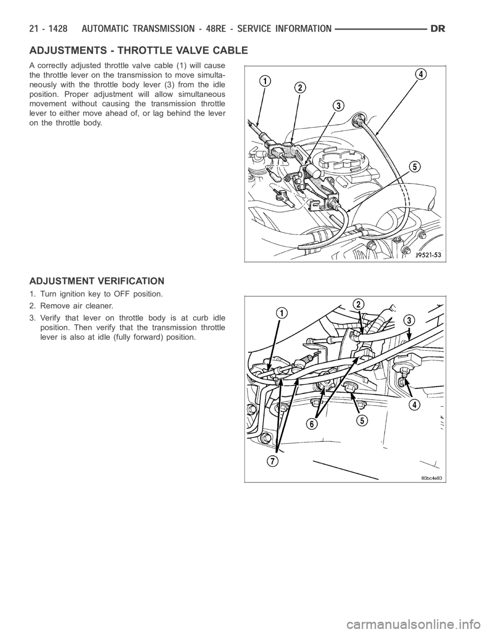
ADJUSTMENTS - THROTTLE VALVE CABLE
A correctly adjusted throttle valve cable (1) will cause
the throttle lever on the transmission to move simulta-
neously with the throttle body lever (3) from the idle
position. Proper adjustment will allow simultaneous
movement without causing the transmission throttle
lever to either move ahead of, or lag behind the lever
on the throttle body.
ADJUSTMENT VERIFICATION
1. Turn ignition key to OFF position.
2. Remove air cleaner.
3. Verify that lever on throttle body is at curb idle
position. Then verify that the transmission throttle
lever is also at idle (fully forward) position.
Page 3950 of 5267
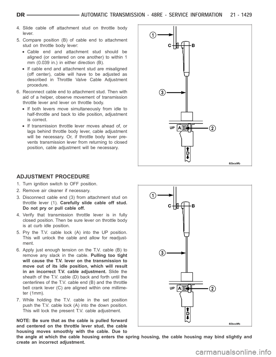
4. Slide cable off attachment stud on throttle body
lever.
5. Compare position (B) of cable end to attachment
stud on throttle body lever:
Cable end and attachment stud should be
aligned (or centered on one another) to within 1
mm (0.039 in.) in either direction (B).
If cable end and attachment stud are misaligned
(off center), cable will have to be adjusted as
described in Throttle Valve Cable Adjustment
procedure.
6. Reconnect cable end to attachment stud. Then with
aid of a helper, observe movement of transmission
throttle lever and lever on throttle body.
If both levers move simultaneously from idle to
half-throttle and back to idle position, adjustment
is correct.
If transmission throttle lever moves ahead of, or
lags behind throttle body lever, cable adjustment
will be necessary. Or, if throttle body lever pre-
vents transmission lever from returning to closed
position, cable adjustment will be necessary.
ADJUSTMENT PROCEDURE
1. Turn ignition switch to OFF position.
2. Remove air cleaner if necessary.
3. Disconnect cable end (3) from attachment stud on
throttle lever (1).Carefully slide cable off stud.
Do not pry or pull cable off.
4. Verify that transmission throttle lever is in fully
closed position. Then be sure lever on throttle body
is at curb idle position.
5. Pry the T.V. cable lock (A) into the UP position.
This will unlock the cable and allow for readjust-
ment.
6. Apply just enough tension on the T.V. cable (B) to
remove any slack in the cable.Pulling too tight
will cause the T.V. lever on the transmission to
move out of its idle position, which will result
in an incorrect T.V. cable adjustment.Slide the
sheath of the T.V. cable (D) back and forth until the
centerlines of the T.V. cable end (B) and the throttle
bell crank lever (C) are aligned within one millime-
ter (1mm).
7. While holding the T.V. cable in the set position
push the T.V. cable lock (A) into the down position.
This will lock the present T.V. cable adjustment.
NOTE:Besurethatasthecableispulledforward
and centered on the throttle lever stud, the cable
housing moves smoothly with the cable. Due to
the angle at which the cable housing enters the spring housing, the cable housing may bind slightly and
create an incorrect adjustment.