DODGE RAM SRT-10 2006 Service Repair Manual
Manufacturer: DODGE, Model Year: 2006, Model line: RAM SRT-10, Model: DODGE RAM SRT-10 2006Pages: 5267, PDF Size: 68.7 MB
Page 4411 of 5267
LATCH
REMOVAL
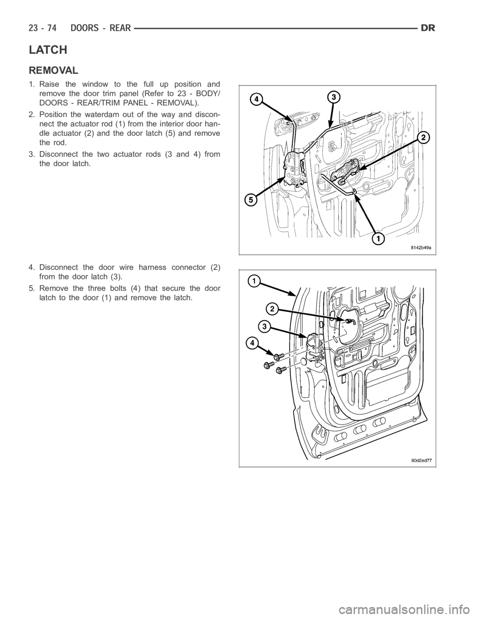
1. Raise the window to the full up position and
remove the door trim panel (Refer to 23 - BODY/
DOORS - REAR/TRIM PANEL - REMOVAL).
2. Position the waterdam out of the way and discon-
nect the actuator rod (1) from the interior door han-
dle actuator (2) and the door latch (5) and remove
the rod.
3. Disconnect the two actuator rods (3 and 4) from
the door latch.
4. Disconnect the door wire harness connector (2)
from the door latch (3).
5. Remove the three bolts (4) that secure the door
latch to the door (1) and remove the latch.
Page 4412 of 5267
INSTALLATION
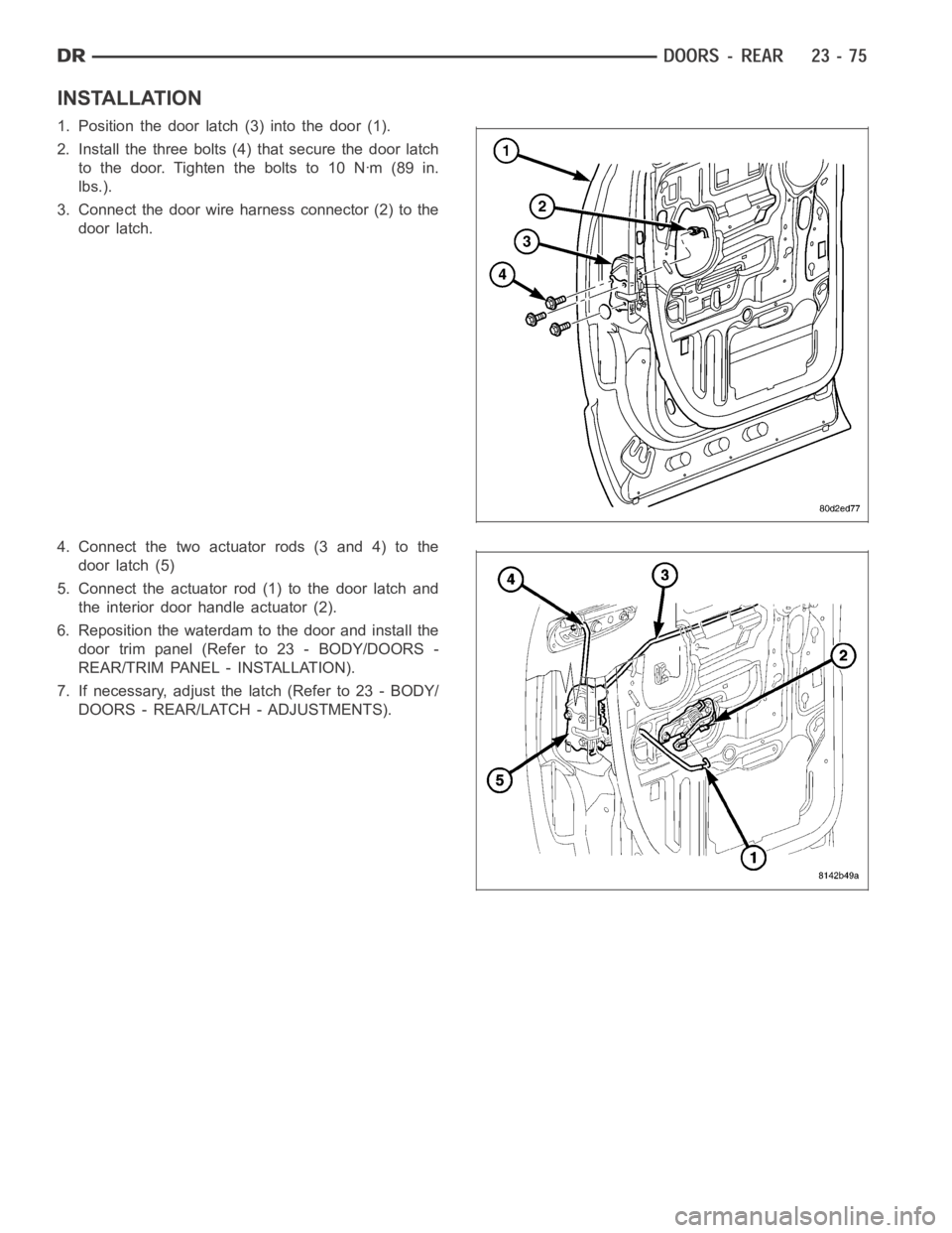
1. Position the door latch (3) into the door (1).
2. Install the three bolts (4) that secure the door latch
to the door. Tighten the bolts to 10 Nꞏm (89 in.
lbs.).
3. Connect the door wire harness connector (2) to the
door latch.
4. Connect the two actuator rods (3 and 4) to the
door latch (5)
5. Connect the actuator rod (1) to the door latch and
the interior door handle actuator (2).
6. Reposition the waterdam to the door and install the
door trim panel (Refer to 23 - BODY/DOORS -
REAR/TRIM PANEL - INSTALLATION).
7. If necessary, adjust the latch (Refer to 23 - BODY/
DOORS - REAR/LATCH - ADJUSTMENTS).
Page 4413 of 5267
ADJUSTMENTS
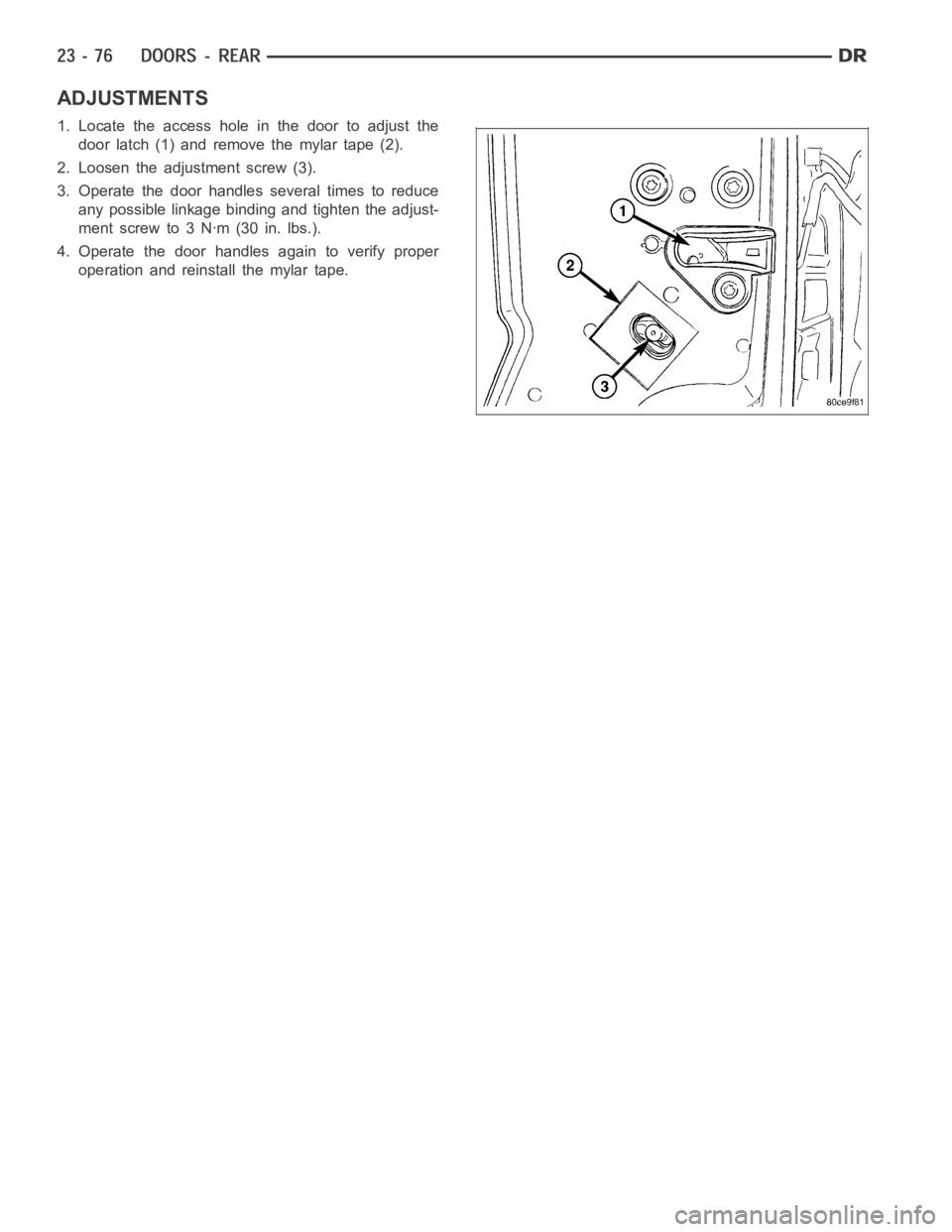
1. Locate the access hole in the door to adjust the
door latch (1) and remove the mylar tape (2).
2. Loosen the adjustment screw (3).
3. Operate the door handles several times to reduce
any possible linkage binding and tighten the adjust-
mentscrewto3Nꞏm(30in.lbs.).
4. Operate the door handles again to verify proper
operation and reinstall the mylar tape.
Page 4414 of 5267
LATCH STRIKER
REMOVAL
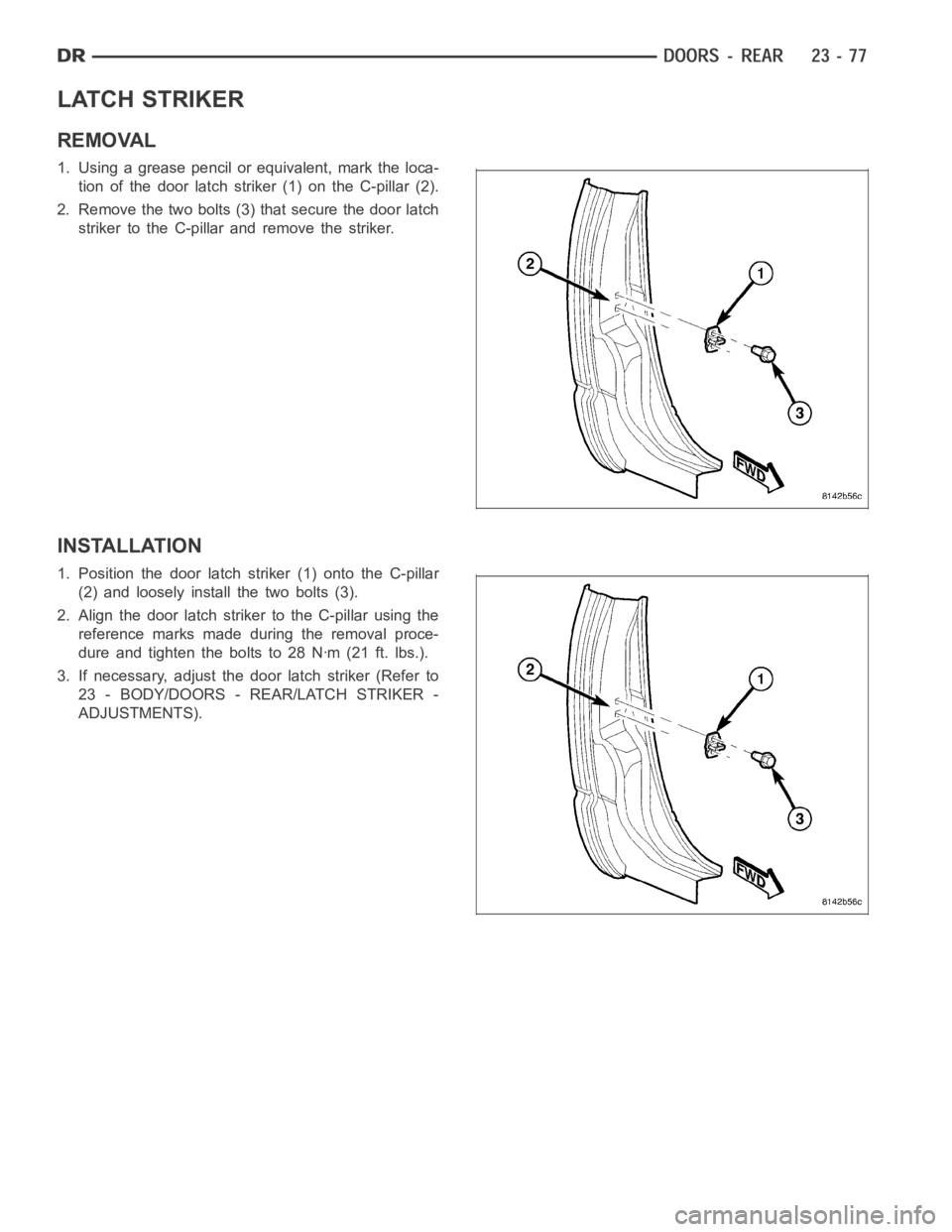
1. Using a grease pencil or equivalent, mark the loca-
tion of the door latch striker (1) on the C-pillar (2).
2. Remove the two bolts (3) that secure the door latch
striker to the C-pillar and remove the striker.
INSTALLATION
1. Position the door latch striker (1) onto the C-pillar
(2) and loosely install the two bolts (3).
2. Align the door latch striker to the C-pillar using the
reference marks made during the removal proce-
dure and tighten the bolts to 28 Nꞏm (21 ft. lbs.).
3. If necessary, adjust the door latch striker (Refer to
23 - BODY/DOORS - REAR/LATCH STRIKER -
ADJUSTMENTS).
Page 4415 of 5267
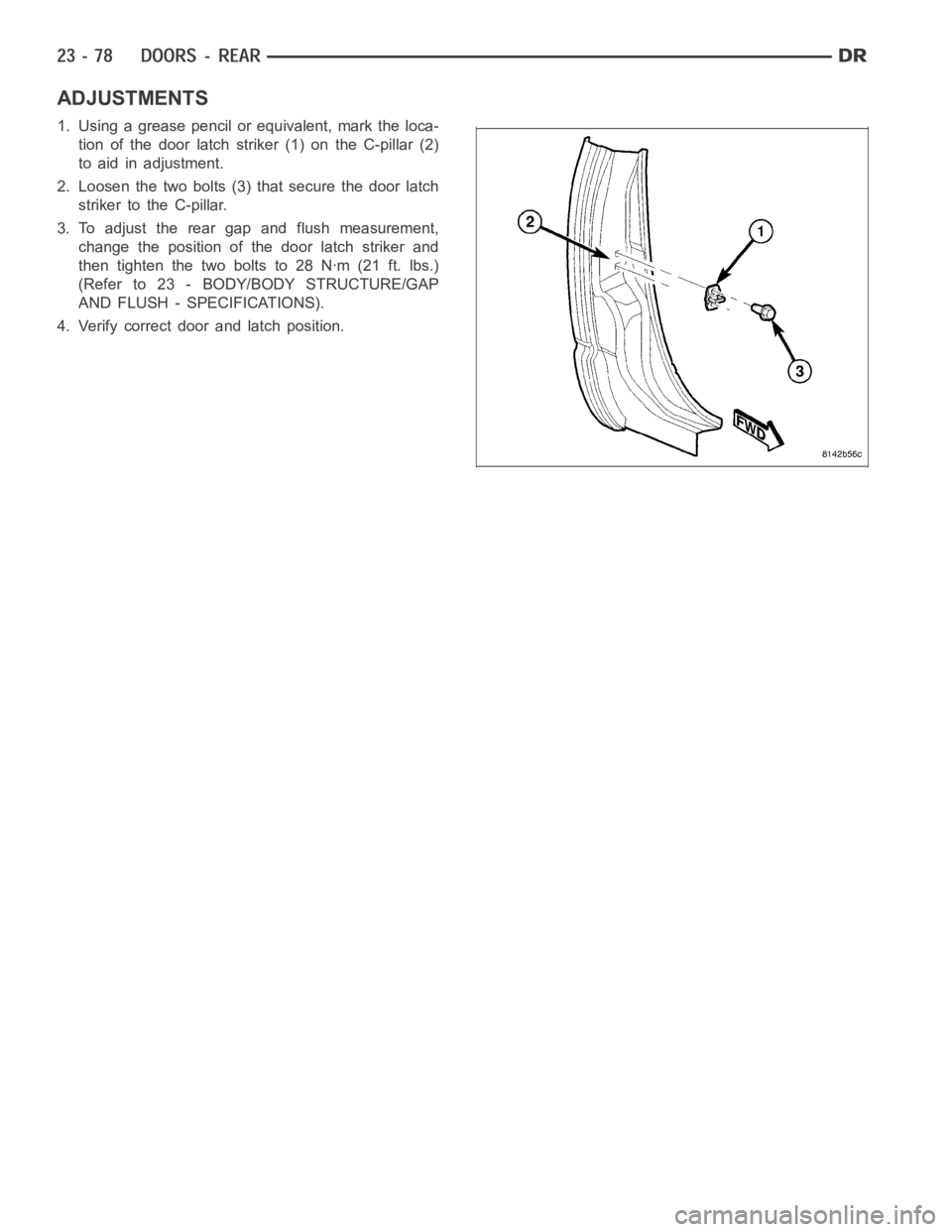
ADJUSTMENTS
1. Using a grease pencil or equivalent, mark the loca-
tion of the door latch striker (1) on the C-pillar (2)
to aid in adjustment.
2. Loosen the two bolts (3) that secure the door latch
striker to the C-pillar.
3. To adjust the rear gap and flush measurement,
change the position of the door latch striker and
then tighten the two bolts to 28 Nꞏm (21 ft. lbs.)
(Refer to 23 - BODY/BODY STRUCTURE/GAP
AND FLUSH - SPECIFICATIONS).
4. Verify correct door and latch position.
Page 4416 of 5267
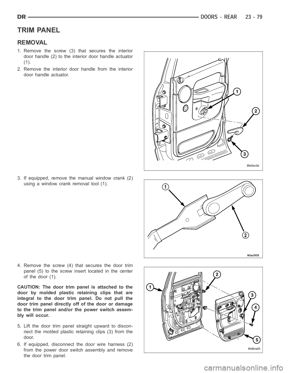
TRIM PANEL
REMOVAL
1. Remove the screw (3) that secures the interior
door handle (2) to the interior door handle actuator
(1).
2. Remove the interior door handle from the interior
door handle actuator.
3. If equipped, remove the manual window crank (2)
using a window crank removal tool (1).
4. Remove the screw (4) that secures the door trim
panel (5) to the screw insert located in the center
of the door (1).
CAUTION: The door trim panel is attached to the
door by molded plastic retaining clips that are
integral to the door trim panel. Do not pull the
door trim panel directly off of the door or damage
to the trim panel and/or the power switch assem-
bly will occur.
5. Lift the door trim panel straight upward to discon-
nect the molded plastic retaining clips (3) from the
door.
6. If equipped, disconnect the door wire harness (2)
from the power door switch assembly and remove
the door trim panel.
Page 4417 of 5267
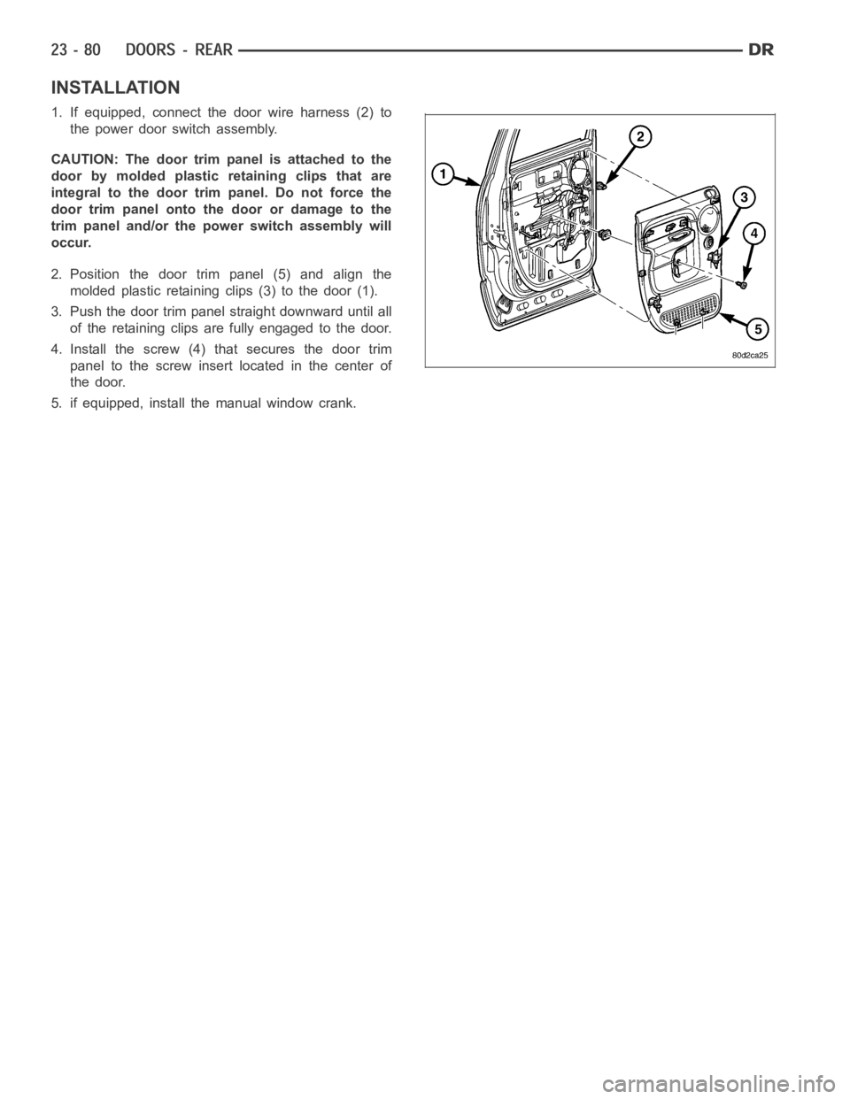
INSTALLATION
1. If equipped, connect the door wire harness (2) to
the power door switch assembly.
CAUTION: The door trim panel is attached to the
door by molded plastic retaining clips that are
integral to the door trim panel. Do not force the
door trim panel onto the door or damage to the
trim panel and/or the power switch assembly will
occur.
2. Position the door trim panel (5) and align the
molded plastic retaining clips (3) to the door (1).
3. Push the door trim panel straight downward until all
of the retaining clips are fully engaged to the door.
4. Install the screw (4) that secures the door trim
panel to the screw insert located in the center of
the door.
5. if equipped, install the manual window crank.
Page 4418 of 5267
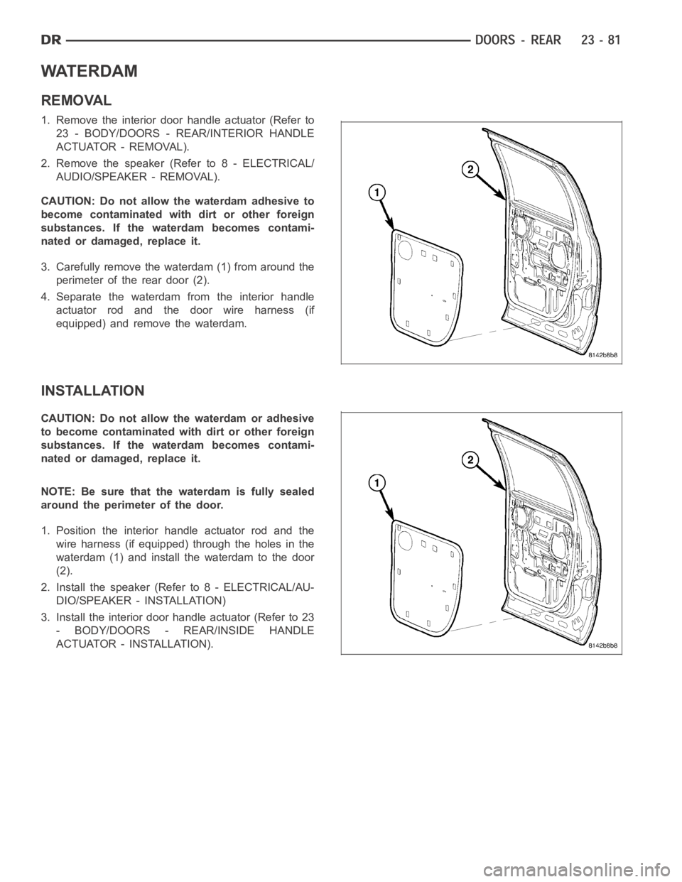
WATERDAM
REMOVAL
1. Remove the interior door handle actuator (Refer to
23 - BODY/DOORS - REAR/INTERIOR HANDLE
ACTUATOR - REMOVAL).
2. Remove the speaker (Refer to 8 - ELECTRICAL/
AUDIO/SPEAKER - REMOVAL).
CAUTION: Do not allow the waterdam adhesive to
become contaminated with dirt or other foreign
substances. If the waterdam becomes contami-
nated or damaged, replace it.
3. Carefully remove the waterdam (1) from around the
perimeter of the rear door (2).
4. Separate the waterdam from the interior handle
actuator rod and the door wire harness (if
equipped) and remove the waterdam.
INSTALLATION
CAUTION: Do not allow the waterdam or adhesive
to become contaminated with dirt or other foreign
substances. If the waterdam becomes contami-
nated or damaged, replace it.
NOTE: Be sure that the waterdam is fully sealed
around the perimeter of the door.
1. Position the interior handle actuator rod and the
wire harness (if equipped) through the holes in the
waterdam (1) and install the waterdam to the door
(2).
2. Install the speaker (Refer to 8 - ELECTRICAL/AU-
DIO/SPEAKER - INSTALLATION)
3. Install the interior door handle actuator (Refer to 23
- BODY/DOORS - REAR/INSIDE HANDLE
A C T U AT O R - I N S TA L L AT I O N ) .
Page 4419 of 5267
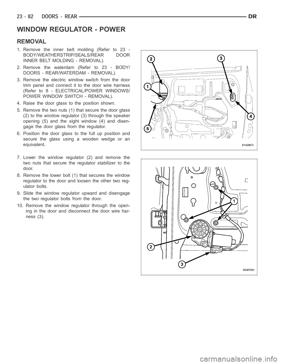
WINDOW REGULATOR - POWER
REMOVAL
1. Remove the inner belt molding (Refer to 23 -
BODY/WEATHERSTRIP/SEALS/REAR DOOR
INNER BELT MOLDING - REMOVAL).
2. Remove the waterdam (Refer to 23 - BODY/
DOORS - REAR/WATERDAM - REMOVAL).
3. Remove the electric window switch from the door
trim panel and connect it to the door wire harness
(Refer to 8 - ELECTRICAL/POWER WINDOWS/
POWER WINDOW SWITCH - REMOVAL).
4. Raisethedoorglasstothepositionshown.
5. Remove the two nuts (1) that secure the door glass
(2) to the window regulator (3) through the speaker
opening (5) and the sight window (4) and disen-
gage the door glass from the regulator.
6. Position the door glass to the full up position and
secure the glass using a wooden wedge or an
equivalent.
7. Lower the window regulator (2) and remove the
two nuts that secure the regulator stabilizer to the
door.
8. Remove the lower bolt (1) that secures the window
regulator to the door and loosen the other two reg-
ulator bolts.
9. Slide the window regulator upward and disengage
the two regulator bolts from the door.
10. Remove the window regulator through the open-
ing in the door and disconnect the door wire har-
ness (3).
Page 4420 of 5267
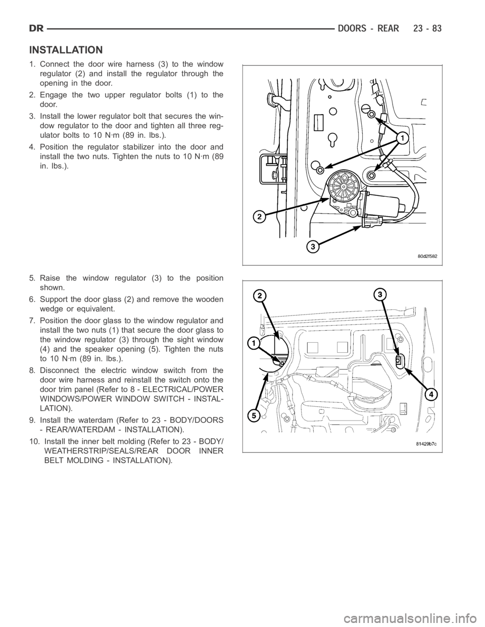
INSTALLATION
1. Connect the door wire harness (3) to the window
regulator (2) and install the regulator through the
opening in the door.
2. Engage the two upper regulator bolts (1) to the
door.
3. Install the lower regulator bolt that secures the win-
dow regulator to the door and tighten all three reg-
ulator bolts to 10 Nꞏm (89 in. lbs.).
4. Position the regulator stabilizer into the door and
install the two nuts. Tighten the nuts to 10 Nꞏm (89
in. lbs.).
5. Raise the window regulator (3) to the position
shown.
6. Support the door glass (2) and remove the wooden
wedge or equivalent.
7. Position the door glass to the window regulator and
install the two nuts (1) that secure the door glass to
the window regulator (3) through the sight window
(4) and the speaker opening (5). Tighten the nuts
to 10 Nꞏm (89 in. lbs.).
8. Disconnect the electric window switch from the
door wire harness and reinstall the switch onto the
door trim panel (Refer to 8 - ELECTRICAL/POWER
WINDOWS/POWER WINDOW SWITCH - INSTAL-
LATION).
9. Install the waterdam (Refer to 23 - BODY/DOORS
- REAR/WATERDAM - INSTALLATION).
10. Install the inner belt molding (Refer to 23 - BODY/
WEATHERSTRIP/SEALS/REAR DOOR INNER
BELT MOLDING - INSTALLATION).