DODGE RAM SRT-10 2006 Service Repair Manual
RAM SRT-10 2006
DODGE
DODGE
https://www.carmanualsonline.info/img/12/56917/w960_56917-0.png
DODGE RAM SRT-10 2006 Service Repair Manual
Trending: towing, inflation pressure, immobilizer, drain bolt, catalytic converter, power steering, remove seats
Page 4441 of 5267
SIDE VIEW MIRROR GLASS
REMOVAL
STANDARD MIRROR
WARNING: Always wear eye and hand protection
when servicing the mirror assembly. Failure to
observe this warning may result in personal injury
from broken glass.
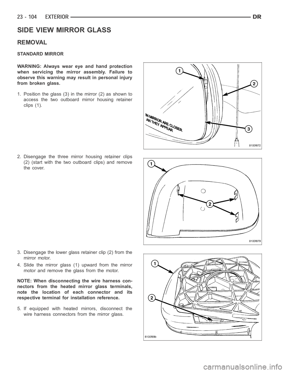
1. Position the glass (3) in the mirror (2) as shown to
access the two outboard mirror housing retainer
clips (1).
2. Disengage the three mirror housing retainer clips
(2) (start with the two outboard clips) and remove
the cover.
3. Disengage the lower glass retainer clip (2) from the
mirror motor.
4. Slide the mirror glass (1) upward from the mirror
motor and remove the glass from the motor.
NOTE: When disconnecting the wire harness con-
nectors from the heated mirror glass terminals,
note the location of each connector and its
respective terminal for installation reference.
5. If equipped with heated mirrors, disconnect the
wire harness connectors from the mirror glass.
Page 4442 of 5267
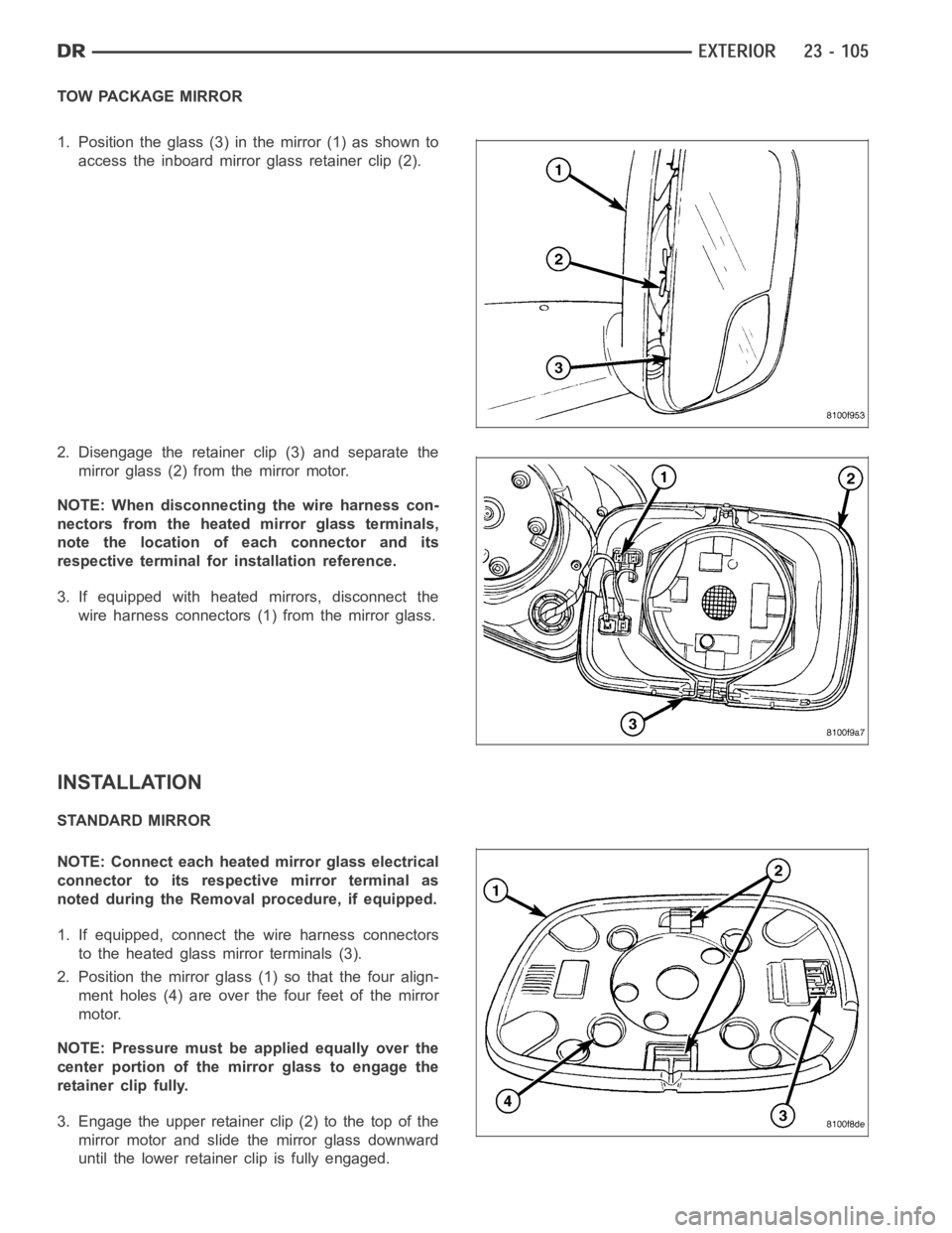
TOW PACKAGE MIRROR
1. Position the glass (3) in the mirror (1) as shown to
access the inboard mirror glass retainer clip (2).
2. Disengage the retainer clip (3) and separate the
mirror glass (2) from the mirror motor.
NOTE: When disconnecting the wire harness con-
nectors from the heated mirror glass terminals,
note the location of each connector and its
respective terminal for installation reference.
3. If equipped with heated mirrors, disconnect the
wire harness connectors (1) from the mirror glass.
INSTALLATION
STANDARD MIRROR
NOTE: Connect each heated mirror glass electrical
connector to its respective mirror terminal as
noted during the Removal procedure, if equipped.
1. If equipped, connect the wire harness connectors
to the heated glass mirror terminals (3).
2. Position the mirror glass (1) so that the four align-
ment holes (4) are over the four feet of the mirror
motor.
NOTE: Pressure must be applied equally over the
center portion of the mirror glass to engage the
retainer clip fully.
3. Engage the upper retainer clip (2) to the top of the
mirror motor and slide the mirror glass downward
until the lower retainerclip is fully engaged.
Page 4443 of 5267
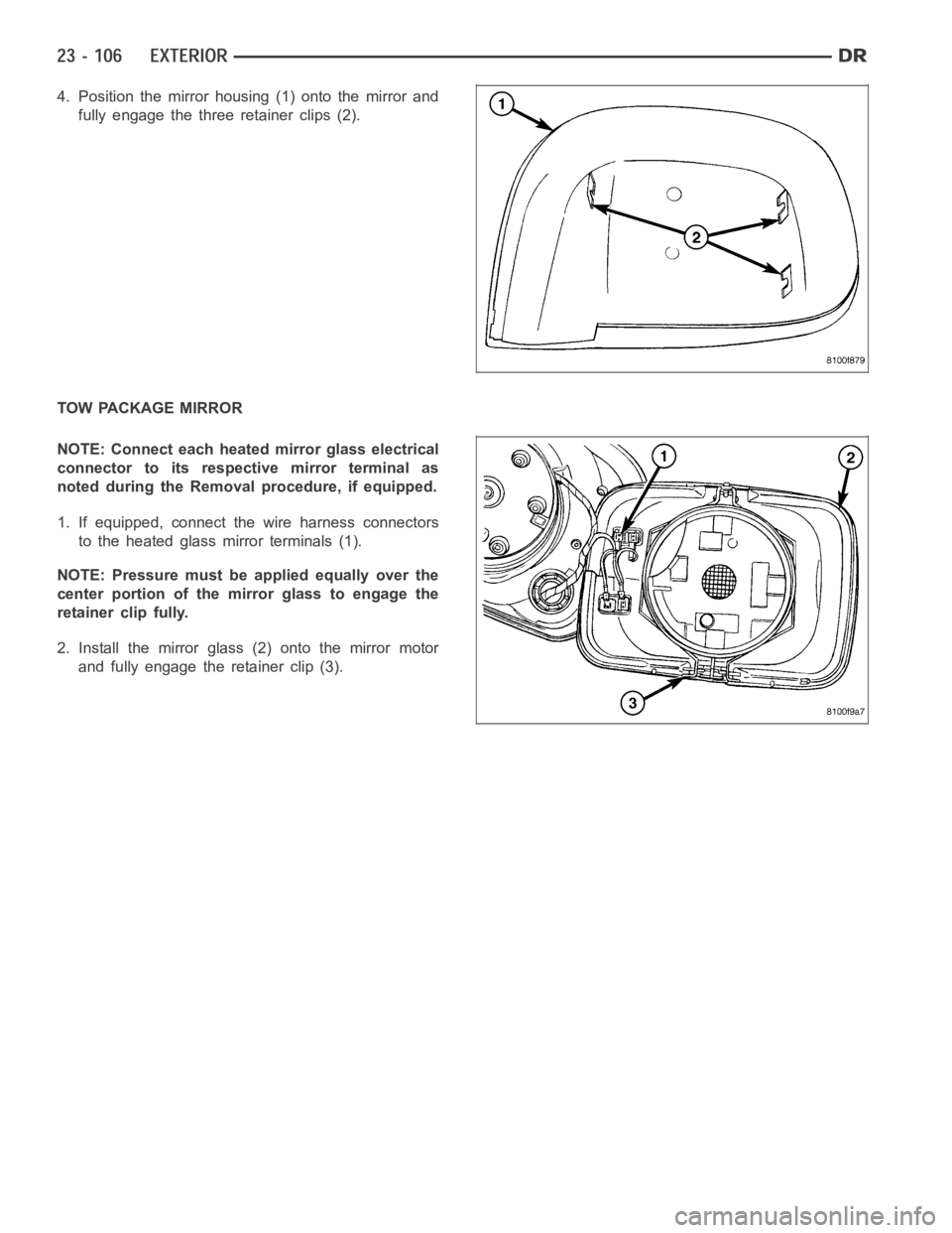
4. Position the mirror housing (1) onto the mirror and
fully engage the three retainer clips (2).
TOW PACKAGE MIRROR
NOTE: Connect each heated mirror glass electrical
connector to its respective mirror terminal as
noted during the Removal procedure, if equipped.
1. If equipped, connect the wire harness connectors
to the heated glass mirror terminals (1).
NOTE: Pressure must be applied equally over the
center portion of the mirror glass to engage the
retainer clip fully.
2. Install the mirror glass (2) onto the mirror motor
and fully engage the retainer clip (3).
Page 4444 of 5267
UPPER RADIATOR CROSSMEMBER
REMOVAL
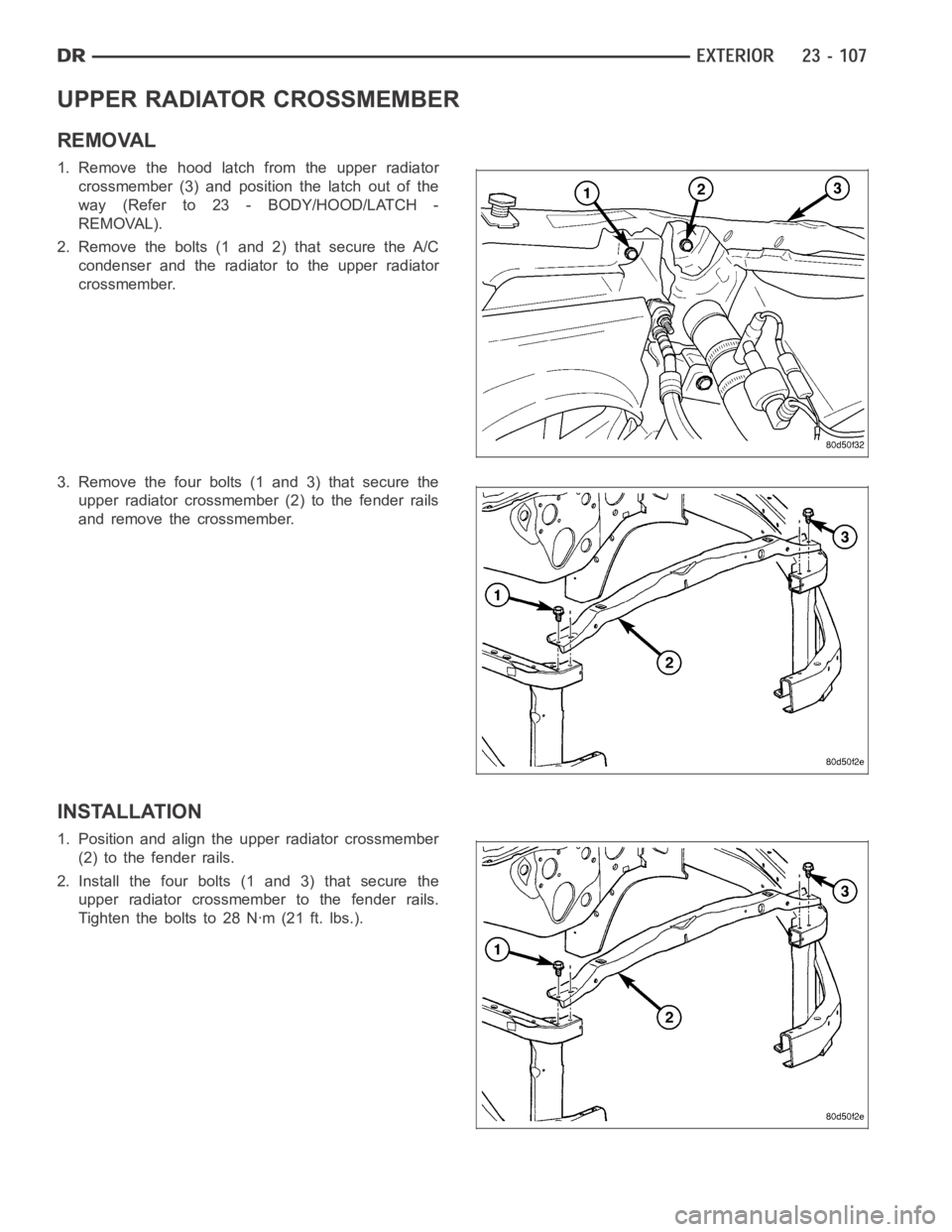
1. Remove the hood latch from the upper radiator
crossmember (3) and position the latch out of the
way(Referto23-BODY/HOOD/LATCH-
REMOVAL).
2. Remove the bolts (1 and 2) that secure the A/C
condenser and the radiator to the upper radiator
crossmember.
3. Remove the four bolts (1 and 3) that secure the
upper radiator crossmember (2) to the fender rails
and remove the crossmember.
INSTALLATION
1. Position and align the upper radiator crossmember
(2) to the fender rails.
2. Install the four bolts (1 and 3) that secure the
upper radiator crossmember to the fender rails.
Tighten the bolts to 28 Nꞏm (21 ft. lbs.).
Page 4445 of 5267
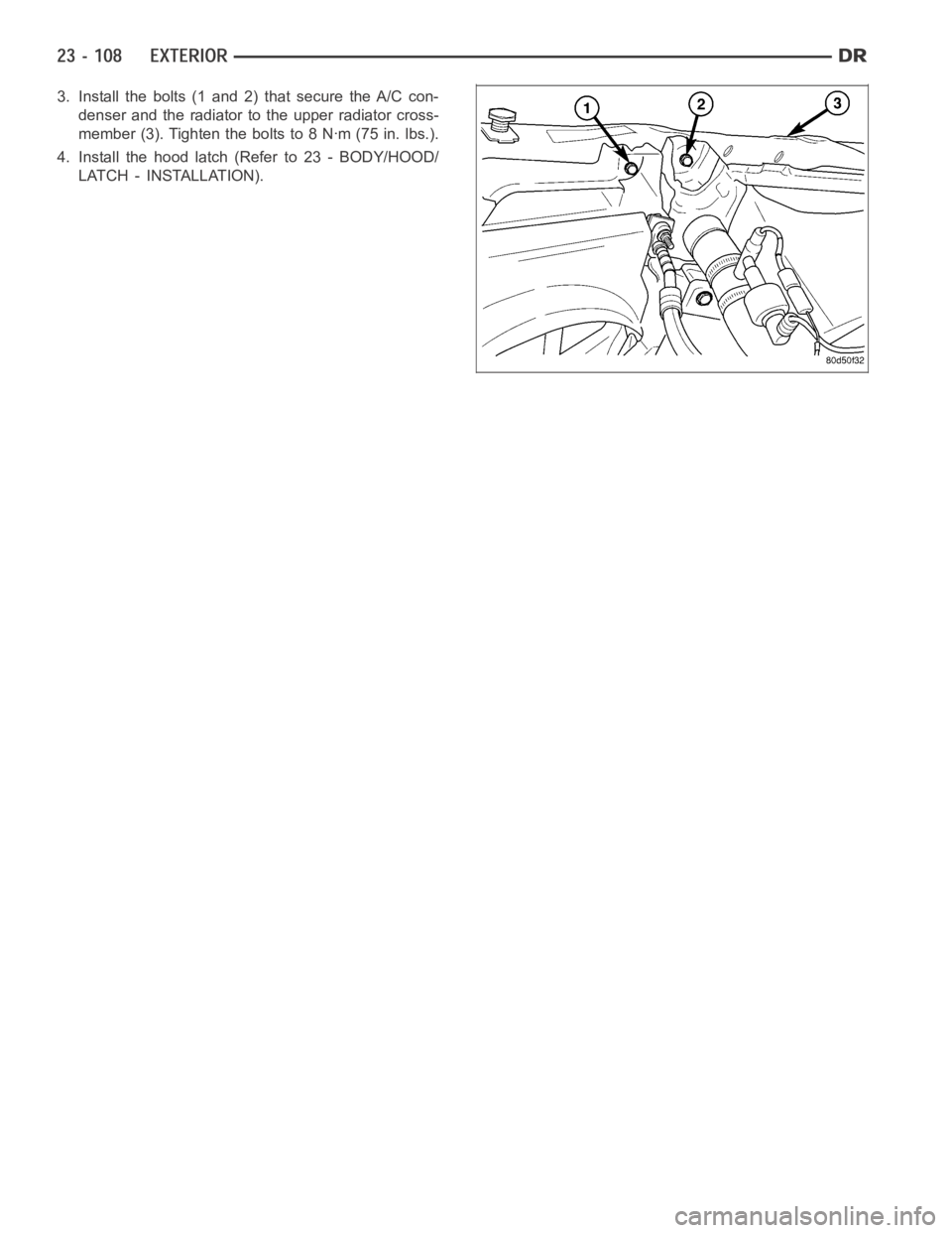
3. Install the bolts (1 and 2) that secure the A/C con-
denser and the radiator to the upper radiator cross-
member (3). Tighten the bolts to 8 Nꞏm (75 in. lbs.).
4. Install the hood latch (Refer to 23 - BODY/HOOD/
LATCH - INSTALLATION).
Page 4446 of 5267
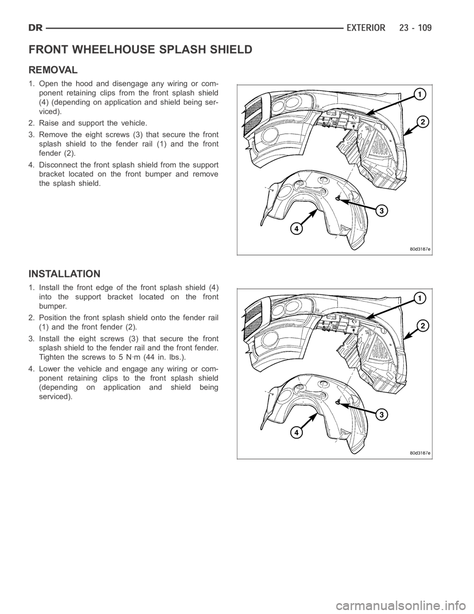
FRONT WHEELHOUSE SPLASH SHIELD
REMOVAL
1. Open the hood and disengage any wiring or com-
ponent retaining clips from the front splash shield
(4) (depending on application and shield being ser-
viced).
2. Raise and support the vehicle.
3. Remove the eight screws (3) that secure the front
splash shield to the fender rail (1) and the front
fender (2).
4. Disconnect the front splash shield from the support
bracket located on the front bumper and remove
the splash shield.
INSTALLATION
1. Install the front edge of the front splash shield (4)
into the support bracket located on the front
bumper.
2. Position the front splash shield onto the fender rail
(1) and the front fender (2).
3. Install the eight screws (3) that secure the front
splash shield to the fender rail and the front fender.
Tighten the screws to 5 Nꞏm (44 in. lbs.).
4. Lower the vehicle and engage any wiring or com-
ponent retaining clips to the front splash shield
(depending on application and shield being
serviced).
Page 4447 of 5267
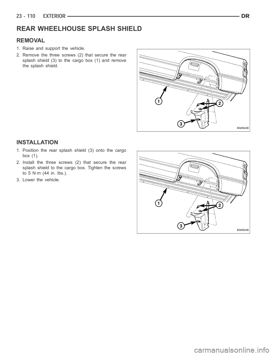
REAR WHEELHOUSE SPLASH SHIELD
REMOVAL
1. Raise and support the vehicle.
2. Remove the three screws (2) that secure the rear
splash shield (3) to the cargo box (1) and remove
the splash shield.
INSTALLATION
1. Position the rear splash shield (3) onto the cargo
box (1).
2. Install the three screws (2) that secure the rear
splash shield to the cargo box. Tighten the screws
to5Nꞏm(44in.lbs.).
3. Lower the vehicle.
Page 4448 of 5267
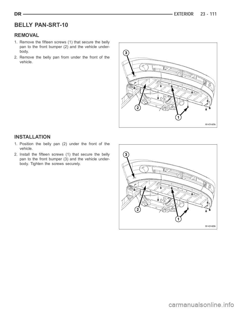
BELLY PAN-SRT-10
REMOVAL
1. Remove the fifteen screws (1) that secure the belly
pan to the front bumper (2) and the vehicle under-
body.
2. Remove the belly pan from under the front of the
vehicle.
INSTALLATION
1. Position the belly pan (2) under the front of the
vehicle.
2. Install the fifteen screws (1) that secure the belly
pan to the front bumper (3) and the vehicle under-
body. Tighten the screws securely.
Page 4449 of 5267
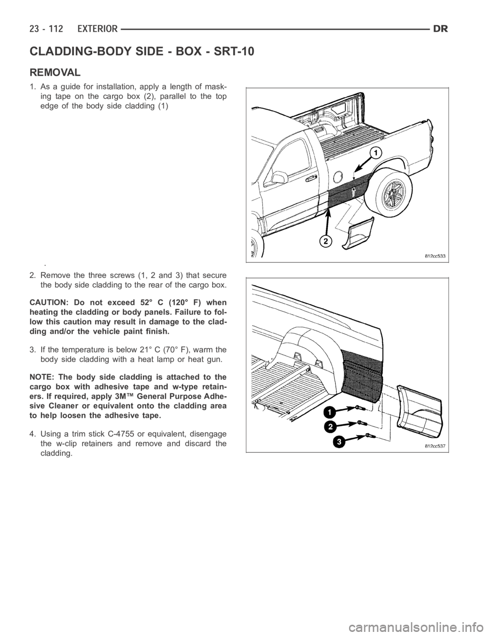
CLADDING-BODY SIDE - BOX - SRT-10
REMOVAL
1. As a guide for installation, apply a length of mask-
ing tape on the cargo box (2), parallel to the top
edge of the body side cladding (1)
.
2. Remove the three screws (1, 2 and 3) that secure
the body side cladding to the rear of the cargo box.
CAUTION: Do not exceed 52° C (120° F) when
heating the cladding or body panels. Failure to fol-
low this caution may result in damage to the clad-
ding and/or the vehicle paint finish.
3. If the temperature is below 21° C (70° F), warm the
body side cladding with a heat lamp or heat gun.
NOTE: The body side cladding is attached to the
cargo box with adhesive tape and w-type retain-
ers. If required, apply 3M™ General Purpose Adhe-
sive Cleaner or equivalent onto the cladding area
to help loosen the adhesive tape.
4. Using a trim stick C-4755 or equivalent, disengage
the w-clip retainers and remove and discard the
cladding.
Page 4450 of 5267
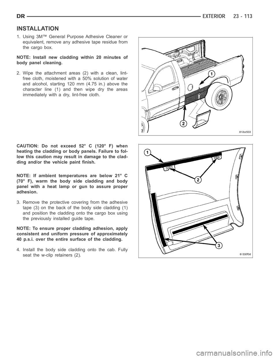
INSTALLATION
1. Using 3M™ General Purpose Adhesive Cleaner or
equivalent, remove any adhesive tape residue from
the cargo box.
NOTE: Install new cladding within 20 minutes of
body panel cleaning.
2. Wipe the attachment areas (2) with a clean, lint-
free cloth, moistened with a 50% solution of water
and alcohol, starting 120 mm (4.75 in.) above the
character line (1) and then wipe dry the areas
immediately with a dry, lint-free cloth.
CAUTION: Do not exceed 52° C (120° F) when
heating the cladding or body panels. Failure to fol-
low this caution may result in damage to the clad-
ding and/or the vehicle paint finish.
NOTE: If ambient temperatures are below 21° C
(70° F), warm the body side cladding and body
panel with a heat lamp or gun to assure proper
adhesion.
3. Remove the protective covering from the adhesive
tape (3) on the back of the body side cladding (1)
and position the cladding onto the cargo box using
the previously installed guide tape.
NOTE: To ensure proper cladding adhesion, apply
consistent and uniform pressure of approximately
40 p.s.i. over the entire surface of the cladding.
4. Install the body side cladding onto the cab. Fully
seat the w-clip retainers (2).
Trending: open hood, glove box, four wheel drive, Compression, fuel consumption, tire size, CD changer
