DODGE RAM SRT-10 2006 Service Repair Manual
Manufacturer: DODGE, Model Year: 2006, Model line: RAM SRT-10, Model: DODGE RAM SRT-10 2006Pages: 5267, PDF Size: 68.7 MB
Page 4451 of 5267
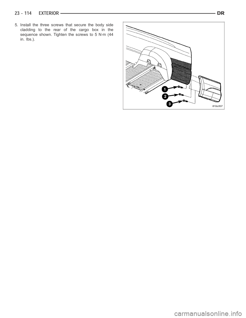
5. Install the three screws that secure the body side
cladding to the rear of the cargo box in the
sequence shown. Tighten the screws to 5 Nꞏm (44
in. lbs.).
Page 4452 of 5267
CLADDING-BODY SIDE - CAB - SRT-10
REMOVAL
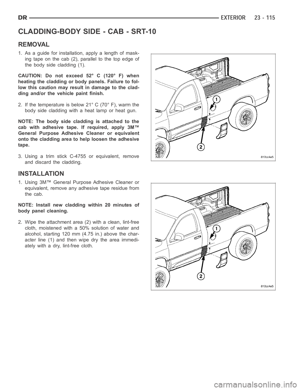
1. As a guide for installation, apply a length of mask-
ingtapeonthecab(2),paralleltothetopedgeof
the body side cladding (1).
CAUTION: Do not exceed 52° C (120° F) when
heating the cladding or body panels. Failure to fol-
low this caution may result in damage to the clad-
ding and/or the vehicle paint finish.
2. If the temperature is below 21° C (70° F), warm the
body side cladding with a heat lamp or heat gun.
NOTE: The body side cladding is attached to the
cab with adhesive tape. If required, apply 3M™
General Purpose Adhesive Cleaner or equivalent
onto the cladding area to help loosen the adhesive
tape.
3. Using a trim stick C-4755 or equivalent, remove
and discard the cladding.
INSTALLATION
1. Using 3M™ General Purpose Adhesive Cleaner or
equivalent, remove any adhesive tape residue from
the cab.
NOTE: Install new cladding within 20 minutes of
body panel cleaning.
2. Wipe the attachment area (2) with a clean, lint-free
cloth, moistened with a 50% solution of water and
alcohol, starting 120 mm (4.75 in.) above the char-
acterline(1)andthenwipedrytheareaimmedi-
ately with a dry, lint-free cloth.
Page 4453 of 5267
CAUTION: Do not exceed 52° C (120° F) when
heating the cladding or body panels. Failure to fol-
low this caution may result in damage to the clad-
ding and/or the vehicle paint finish.
NOTE: If ambient temperatures are below 21° C
(70° F), warm the body side cladding and body
panel with a heat lamp or gun to assure proper
adhesion.
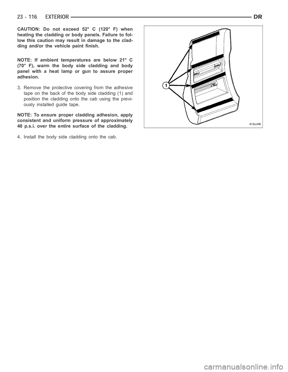
3. Remove the protective covering from the adhesive
tape on the back of the body side cladding (1) and
position the cladding onto the cab using the previ-
ously installed guide tape.
NOTE: To ensure proper cladding adhesion, apply
consistent and uniform pressure of approximately
40 p.s.i. over the entire surface of the cladding.
4. Install the body side cladding onto the cab.
Page 4454 of 5267
CLADDING-BODY SIDE - DOOR - SRT-10
REMOVAL
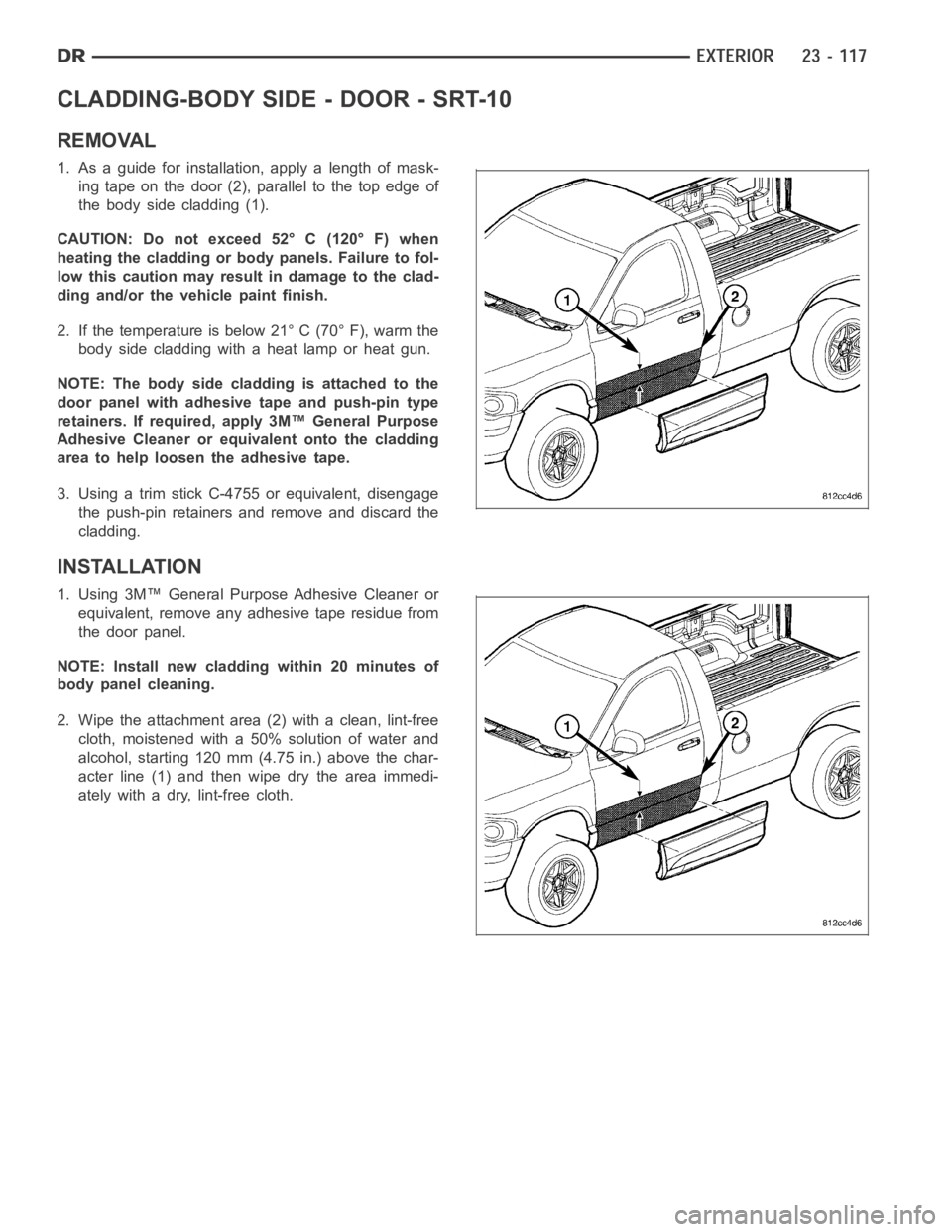
1. As a guide for installation, apply a length of mask-
ing tape on the door (2), parallel to the top edge of
the body side cladding (1).
CAUTION: Do not exceed 52° C (120° F) when
heating the cladding or body panels. Failure to fol-
low this caution may result in damage to the clad-
ding and/or the vehicle paint finish.
2. If the temperature is below 21° C (70° F), warm the
body side cladding with a heat lamp or heat gun.
NOTE: The body side cladding is attached to the
door panel with adhesive tape and push-pin type
retainers. If required, apply 3M™ General Purpose
Adhesive Cleaner or equivalent onto the cladding
area to help loosen the adhesive tape.
3. Using a trim stick C-4755 or equivalent, disengage
the push-pin retainers and remove and discard the
cladding.
INSTALLATION
1. Using 3M™ General Purpose Adhesive Cleaner or
equivalent, remove any adhesive tape residue from
the door panel.
NOTE: Install new cladding within 20 minutes of
body panel cleaning.
2. Wipe the attachment area (2) with a clean, lint-free
cloth, moistened with a 50% solution of water and
alcohol, starting 120 mm (4.75 in.) above the char-
acterline(1)andthenwipedrytheareaimmedi-
ately with a dry, lint-free cloth.
Page 4455 of 5267
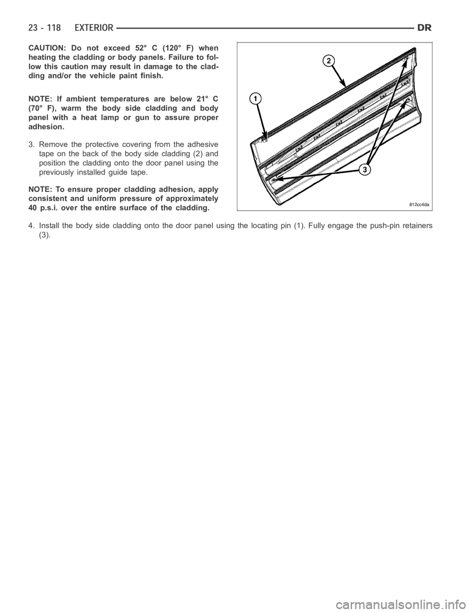
CAUTION: Do not exceed 52° C (120° F) when
heating the cladding or body panels. Failure to fol-
low this caution may result in damage to the clad-
ding and/or the vehicle paint finish.
NOTE: If ambient temperatures are below 21° C
(70° F), warm the body side cladding and body
panel with a heat lamp or gun to assure proper
adhesion.
3. Remove the protective covering from the adhesive
tape on the back of the body side cladding (2) and
position the cladding onto the door panel using the
previously installed guide tape.
NOTE: To ensure proper cladding adhesion, apply
consistent and uniform pressure of approximately
40 p.s.i. over the entire surface of the cladding.
4. Install the body side cladding onto the door panel using the locating pin(1). Fully engage the push-pin retainers
(3).
Page 4456 of 5267
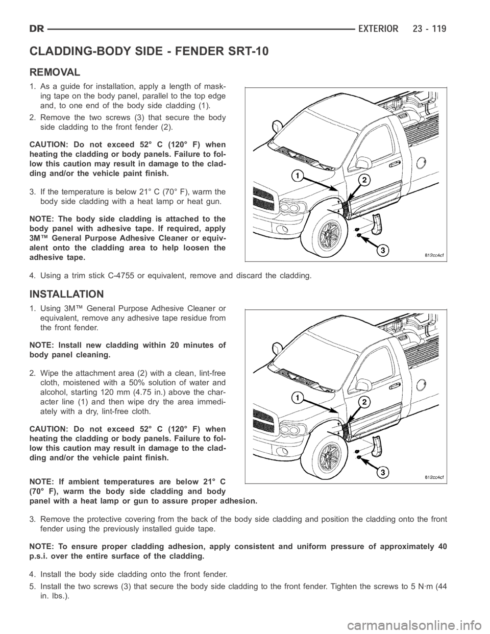
CLADDING-BODY SIDE - FENDER SRT-10
REMOVAL
1. As a guide for installation, apply a length of mask-
ing tape on the body panel, parallel to the top edge
and, to one end of the body side cladding (1).
2. Remove the two screws (3) that secure the body
side cladding to the front fender (2).
CAUTION: Do not exceed 52° C (120° F) when
heating the cladding or body panels. Failure to fol-
low this caution may result in damage to the clad-
ding and/or the vehicle paint finish.
3. If the temperature is below 21° C (70° F), warm the
body side cladding with a heat lamp or heat gun.
NOTE: The body side cladding is attached to the
body panel with adhesive tape. If required, apply
3M™ General Purpose Adhesive Cleaner or equiv-
alent onto the cladding area to help loosen the
adhesive tape.
4. Using a trim stick C-4755 or equivalent, remove and discard the cladding.
INSTALLATION
1. Using 3M™ General Purpose Adhesive Cleaner or
equivalent, remove any adhesive tape residue from
the front fender.
NOTE: Install new cladding within 20 minutes of
body panel cleaning.
2. Wipe the attachment area (2) with a clean, lint-free
cloth, moistened with a 50% solution of water and
alcohol, starting 120 mm (4.75 in.) above the char-
acterline(1)andthenwipedrytheareaimmedi-
ately with a dry, lint-free cloth.
CAUTION: Do not exceed 52° C (120° F) when
heating the cladding or body panels. Failure to fol-
low this caution may result in damage to the clad-
ding and/or the vehicle paint finish.
NOTE: If ambient temperatures are below 21° C
(70° F), warm the body side cladding and body
panel with a heat lamp or gun to assure proper adhesion.
3. Remove the protective covering from the back of the body side cladding and position the cladding onto the front
fender using the previously installed guide tape.
NOTE: To ensure proper cladding adhesion, apply consistent and uniform pressure of approximately 40
p.s.i. over the entire surface of the cladding.
4. Install the body side cladding onto the front fender.
5. Install the two screws (3) that secure the body side cladding to the frontfender. Tighten the screws to 5 Nꞏm (44
in. lbs.).
Page 4457 of 5267
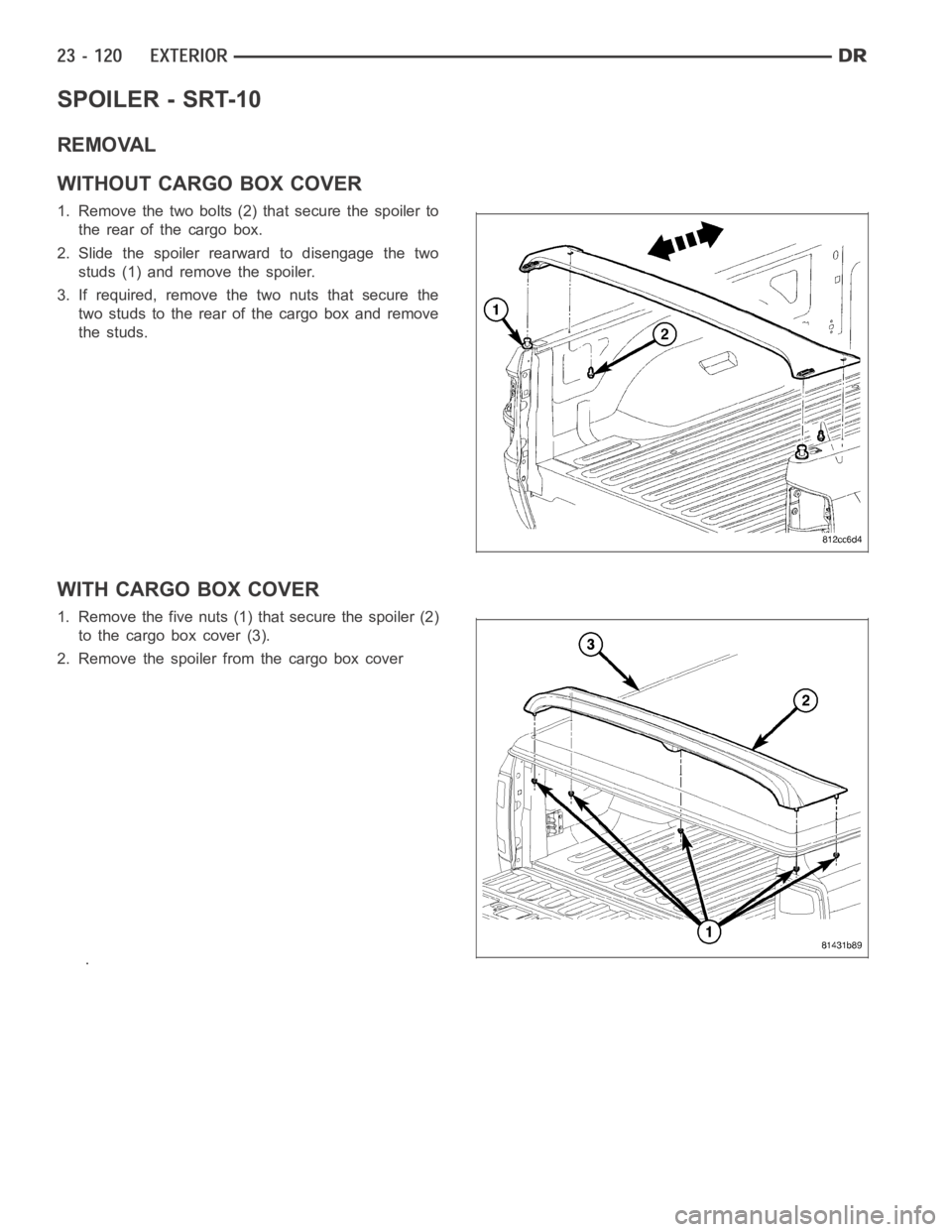
SPOILER - SRT-10
REMOVAL
WITHOUT CARGO BOX COVER
1. Remove the two bolts (2) that secure the spoiler to
the rear of the cargo box.
2. Slide the spoiler rearward to disengage the two
studs (1) and remove the spoiler.
3. If required, remove the two nuts that secure the
two studs to the rear of the cargo box and remove
the studs.
WITH CARGO BOX COVER
1. Remove the five nuts (1) that secure the spoiler (2)
to the cargo box cover (3).
2. Remove the spoiler from the cargo box cover
.
Page 4458 of 5267
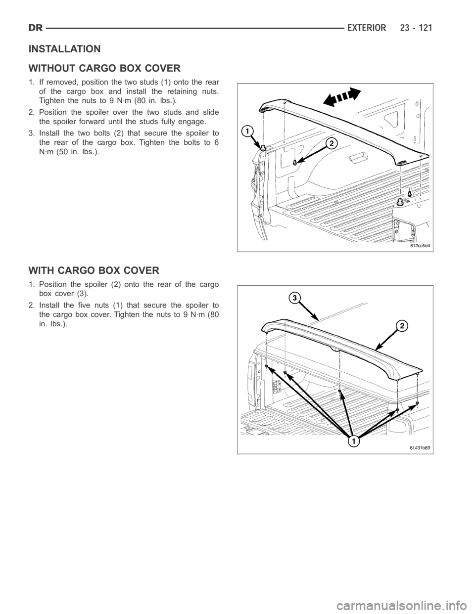
INSTALLATION
WITHOUT CARGO BOX COVER
1. If removed, position the two studs (1) onto the rear
of the cargo box and install the retaining nuts.
Tightenthenutsto9Nꞏm(80in.lbs.).
2. Position the spoiler over the two studs and slide
the spoiler forward until the studs fully engage.
3. Install the two bolts (2) that secure the spoiler to
the rear of the cargo box. Tighten the bolts to 6
Nꞏm (50 in. lbs.).
WITH CARGO BOX COVER
1. Position the spoiler (2) onto the rear of the cargo
box cover (3).
2. Install the five nuts (1) that secure the spoiler to
the cargo box cover. Tighten the nuts to 9 Nꞏm (80
in. lbs.).
Page 4459 of 5267
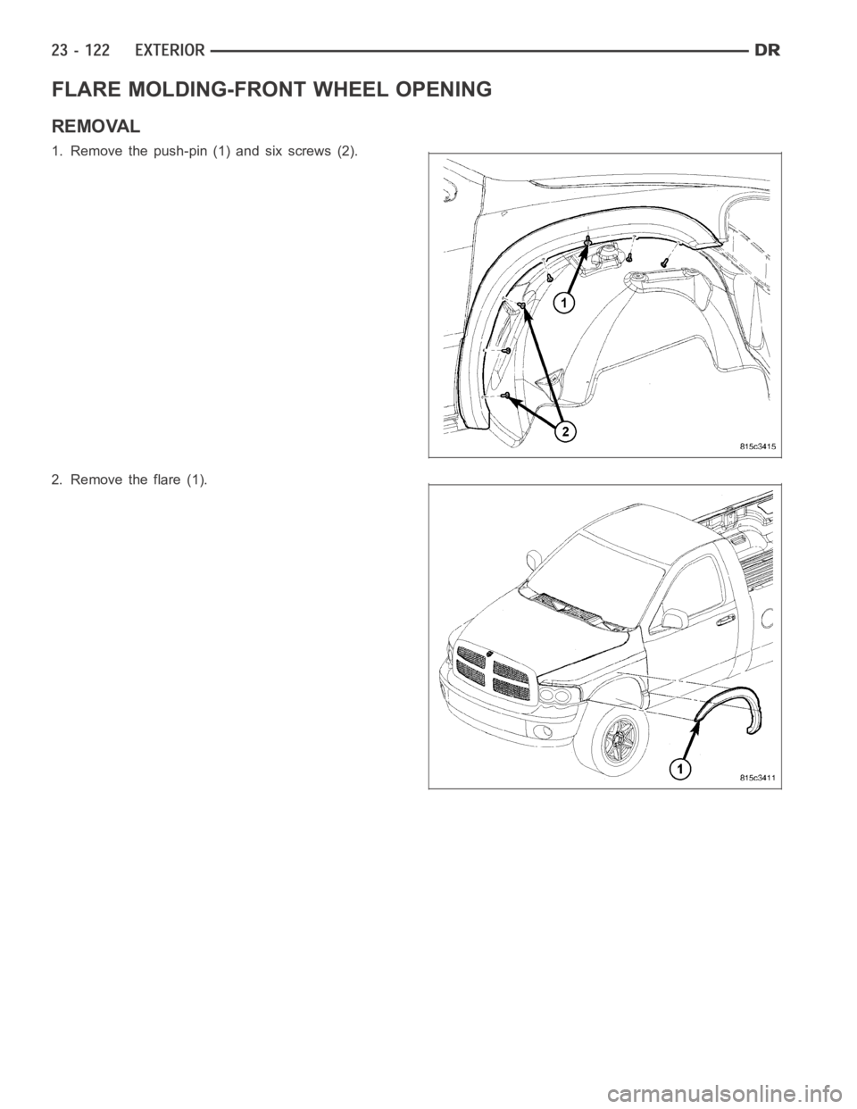
FLARE MOLDING-FRONT WHEEL OPENING
REMOVAL
1. Remove the push-pin (1) and six screws (2).
2. Remove the flare (1).
Page 4460 of 5267
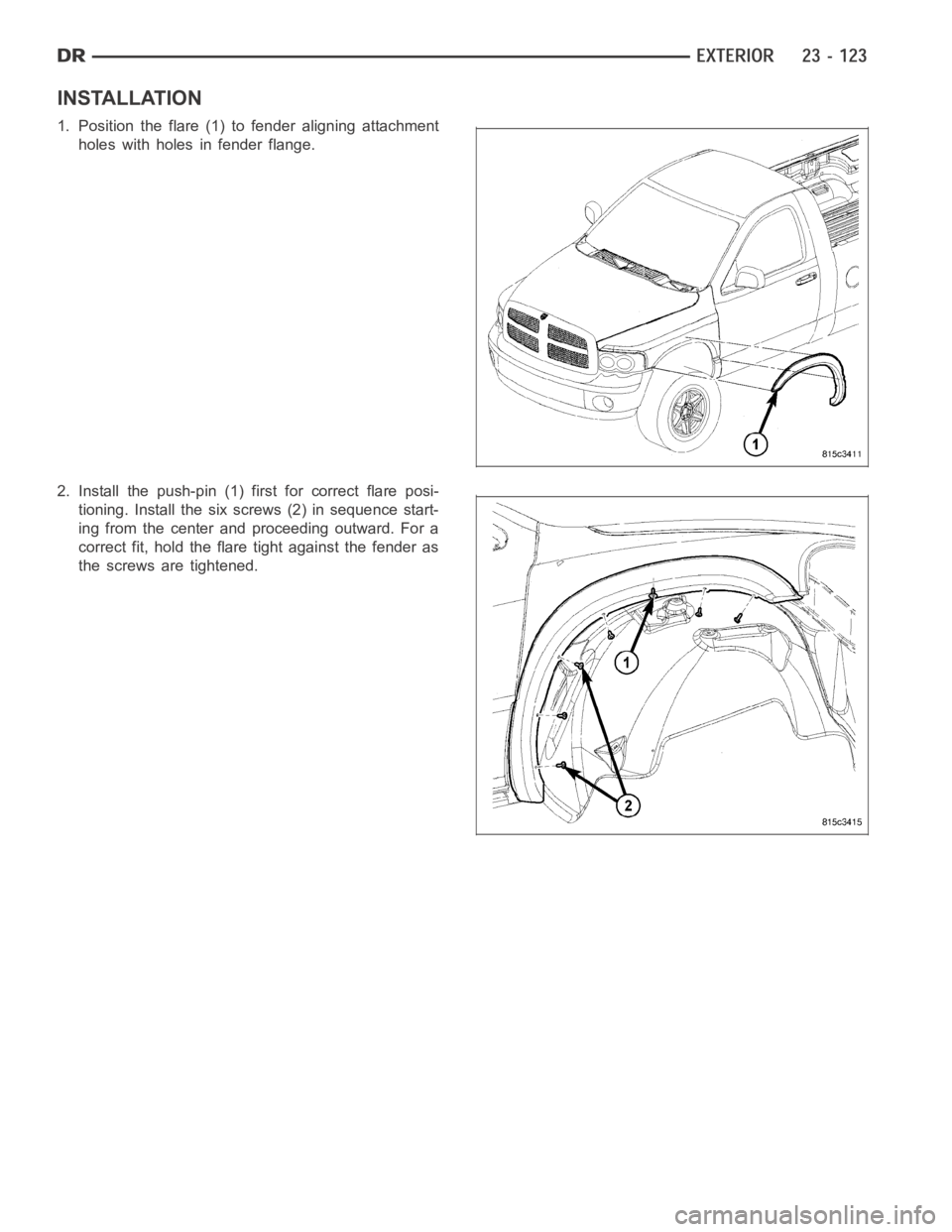
INSTALLATION
1. Position the flare (1) to fender aligning attachment
holes with holes in fender flange.
2. Install the push-pin (1) first for correct flare posi-
tioning. Install the six screws (2) in sequence start-
ing from the center and proceeding outward. For a
correct fit, hold the flare tight against the fender as
the screws are tightened.