glove box DODGE SPRINTER 2007 2.G Owners Manual
[x] Cancel search | Manufacturer: DODGE, Model Year: 2007, Model line: SPRINTER, Model: DODGE SPRINTER 2007 2.GPages: 393, PDF Size: 7.61 MB
Page 14 of 393
13 At a glance
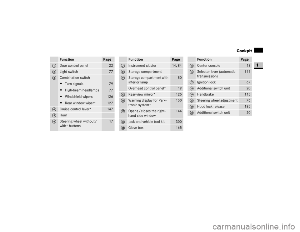
Cockpit
1
Function
Page
1
Door control panel
22
2
Light switch
77
3
Combination switch\4Turn signals
\4High-beam headlamps
\4Windshield wipers
\4Rear window wiper*
79
77
126
127
4
Cruise control lever*
147
5
Horn
6
Steering wheel without/
with* buttons
17
Function
Page
7
Instrument cluster
14, 84
8
Storage compartment
9
Storage compartment with
interior lamp
80
Overhead control panel*
19
a
Rear-view mirror*
125
b
Warning display for Park-
tronic system*
150
c
Opens / closes the right-
hand side window
144
d
Jack and vehicle tool kit
300
e
Glove box
165
Function
Page
f
Center console
18
g
Selector lever (automatic
transmission)
111
h
Ignition lock
67
j
Additional switch unit
20
k
Handbrake
115
l
Steering wheel adjustment
76
m
Hood lock release
185
n
Additional switch unit
20
Page 33 of 393
32 SafetyOccupant safety
2
Your vehicle is equipped with the following
airbags, depending on the equipment ver-
sion:
\4Driver’s front airbag, located in the
steering wheel
\4Co-driver’s front airbag, located above
the glove box
\4Thorax sidebags* in the outer sides of
the driver’s seat and the co-driver’s in-
dividual seat
\4Windowbags* in the side of the roof
frame between the A and B-pillars
Each airbag's cover is marked with the let-
ters "SRS/AIRBAG" or "AIRBAG".How airbags work
An airbag inflates within milliseconds. The
1 warning lamp in the instrument clus-
ter comes on.
Airbag inflation slows down and restricts
the movement of the vehicle occupant.
When the vehicle occupant makes contact
with the airbag, hot gas flows out of the in-
flated airbag. This reduces the load on the
head and upper body of the vehicle occu-
pant. The airbag is therefore in a deflated
state after an accident.
\4Do not put your feet on the dashboard.
\4Do not lean on the doors from inside the
vehicle.
\4Make sure that no persons, animals or
objects are present between the vehicle
occupants and the deployment range of
the airbags.
\4Do not cover the padded boss of the
steering wheel, the co-driver’s airbag
cover, the windowbag cover or the
thorax / sidebag cover with film or other
material. Do not affix any badges or
stickers to these areas.
\4Do not hang any hard objects, for exam-
ple coat hangers, on the grab handles or
coat hooks.
\4Do not place any items in the storage
compartment above the co-driver’s air-
bag if they protrude from the compart-
ment. The co-driver’s airbag must be
able to inflate unimpeded.
The risk of injuries from an airbag cannot be
entirely ruled out due to the high speed at
which the airbag is required to inflate.
iIf the airbags are triggered, you will
hear a bang and a small amount of dust
may also be released. The bang will not
damage your hearing and the dust does
not constitute a health hazard.
Page 34 of 393
33 Safety
Occupant safety
2
Front airbags
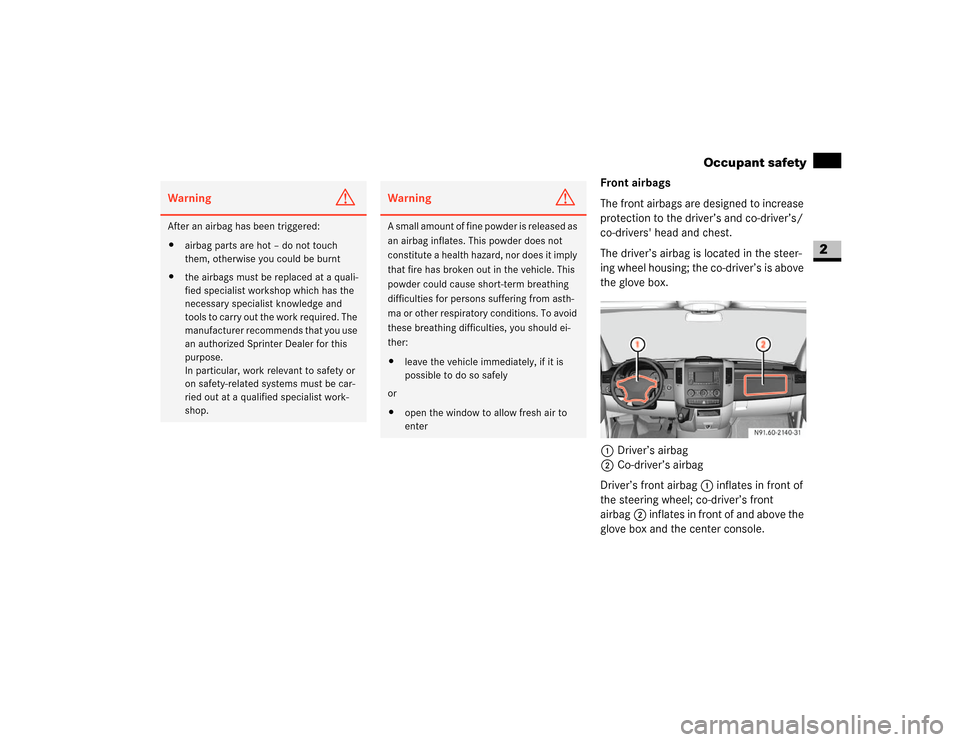
The front airbags are designed to increase
protection to the driver’s and co-driver’s/
co-drivers' head and chest.
The driver’s airbag is located in the steer-
ing wheel housing; the co-driver’s is above
the glove box.
1Driver’s airbag
2Co-driver’s airbag
Driver’s front airbag1 inflates in front of
the steering wheel; co-driver’s front
airbag2 inflates in front of and above the
glove box and the center console.
Warning
G
After an airbag has been triggered:
\4airbag parts are hot – do not touch
them, otherwise you could be burnt
\4the airbags must be replaced at a quali-
fied specialist workshop which has the
necessary specialist knowledge and
tools to carry out the work required. The
manufacturer recommends that you use
an authorized Sprinter Dealer for this
purpose.
In particular, work relevant to safety or
on safety-related systems must be car-
ried out at a qualified specialist work-
shop.
Warning
G
A small amount of fine powder is released as
an airbag inflates. This powder does not
constitute a health hazard, nor does it imply
that fire has broken out in the vehicle. This
powder could cause short-term breathing
difficulties for persons suffering from asth-
ma or other respiratory conditions. To avoid
these breathing difficulties, you should ei-
ther:
\4leave the vehicle immediately, if it is
possible to do so safely
or
\4open the window to allow fresh air to
enter
N91.60-2140-31
Page 137 of 393
136 Controls in detailTempmatic
3
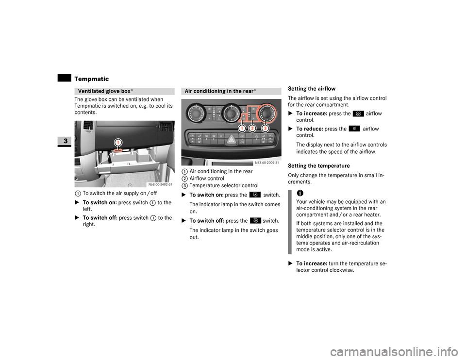
The glove box can be ventilated when
Tempmatic is switched on, e.g. to cool its
contents.
1To switch the air supply on / off
\1To switch on: press switch1 to the
left.
\1To switch off: press switch1 to the
right.1Air conditioning in the rear
2Airflow control
3Temperature selector control
\1To switch on: press the switch.
The indicator lamp in the switch comes
on.
\1To switch off: press the switch.
The indicator lamp in the switch goes
out.Setting the airflow
The airflow is set using the airflow control
for the rear compartment.
\1To increase: press theQ airflow
control.
\1To reduce: press the airflow
control.
The display next to the airflow controls
indicates the speed of the airflow.
Setting the temperature
Only change the temperature in small in-
crements.
\1To increase: turn the temperature se-
lector control clockwise.Ventilated glove box*
Air conditioning in the rear*
N83.60-2009-31
iYour vehicle may be equipped with an
air-conditioning system in the rear
compartment and / or a rear heater.
If both systems are installed and the
temperature selector control is in the
middle position, only one of the sys-
tems operates and air-recirculation
mode is active.
Page 166 of 393
165 Controls in detail
Features
3
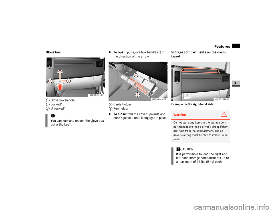
Glove box
1Glove box handle
2Locked*
3Unlocked*\1To open: pull glove box handle 1 in
the direction of the arrow.
4Cards holder
5Pen holder
\1To close: fold the cover upwards and
push against it until it engages in place.Storage compartments on the dash-
board
Example on the right-hand side
iYou can lock and unlock the glove box
using the key*.
Warning
G
Do not store any items in the storage com-
partment above the co-driver’s airbag if they
protrude from the compartment. The co-
driver’s airbag must be able to inflate unim-
peded.!
CAUTION
It is permissible to load the right and
left-hand storage compartments up to
a maximum of 11 lbs (5 kg) each.
Page 305 of 393
304 Practical hintsWhere will I find...?
5
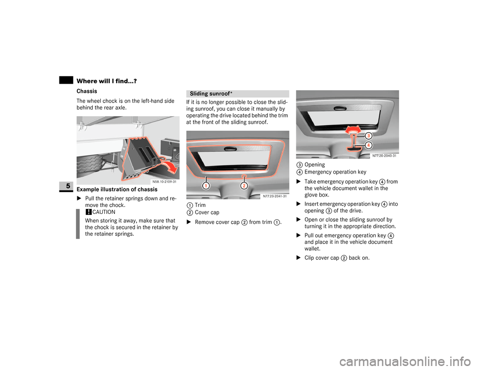
Chassis
The wheel chock is on the left-hand side
behind the rear axle.
Example illustration of chassis
\1Pull the retainer springs down and re-
move the chock.If it is no longer possible to close the slid-
ing sunroof, you can close it manually by
operating the drive located behind the trim
at the front of the sliding sunroof.
1Trim
2Cover cap
\1Remove cover cap2 from trim1.3Opening
4Emergency operation key
\1Take emergency operation key 4 from
the vehicle document wallet in the
glove box.
\1Insert emergency operation key 4 into
opening3 of the drive.
\1Open or close the sliding sunroof by
turning it in the appropriate direction.
\1Pull out emergency operation key 4
and place it in the vehicle document
wallet.
\1Clip cover cap2 back on.
!
CAUTION
When storing it away, make sure that
the chock is secured in the retainer by
the retainer springs.
Sliding sunroof*
N77.20-2041-31
N77.20-2040-31
Page 346 of 393
345 Practical hintsFuses
5
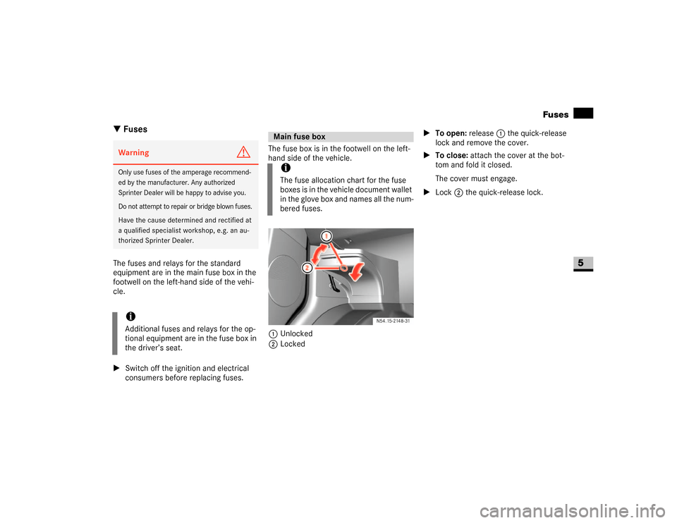
\3 FusesThe fuses and relays for the standard
equipment are in the main fuse box in the
footwell on the left-hand side of the vehi-
cle.
\1Switch off the ignition and electrical
consumers before replacing fuses.The fuse box is in the footwell on the left-
hand side of the vehicle.
1Unlocked
2Locked\1To open: release1 the quick-release
lock and remove the cover.
\1To close: attach the cover at the bot-
tom and fold it closed.
The cover must engage.
\1Lock2 the quick-release lock.Warning
G
Only use fuses of the amperage recommend-
ed by the manufacturer. Any authorized
Sprinter Dealer will be happy to advise you.
Do not attempt to repair or bridge blown fuses.Have the cause determined and rectified at
a qualified specialist workshop, e.g. an au-
thorized Sprinter Dealer.iAdditional fuses and relays for the op-
tional equipment are in the fuse box in
the driver’s seat.
Main fuse boxiThe fuse allocation chart for the fuse
boxes is in the vehicle document wallet
in the glove box and names all the num-
bered fuses.
N54.15-2148-31
Page 348 of 393
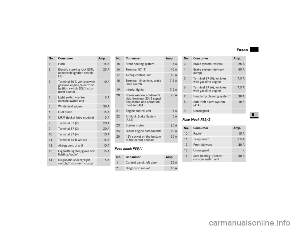
347 Practical hintsFuses
5
Fuse block F55/1Fuse block F55/2
No.
Consumer
Amp.
1
Horn
15 A
2
Electric steering lock ESTL
(electronic ignition switch
EIS)
25 A
3
Te rm ina l 30 Z , ve hi cle s wit h
gasoline engine/electronic
ignition switch EIS/instru-
ment cluster
10 A
4
Light switch/center
console switch unit
5A
5
Windshield wipers
30 A
6
Fuel pump
15 A
7
MRM (jacket tube module)
5A
8
Terminal 87 (2)
20 A
9
Terminal 87 (3)
20 A
10
Terminal 87 (4)
10 A
11
Terminal 15 R vehicle
15 A
12
Airbag control unit
10 A
13
Cigarette lighter/glove box
lighting/radio*
15 A
14
Diagnostic socket/light
switch/instrument cluster
5A
No.
Consumer
Amp.
15
Front heating system
5A
16
Terminal 87 (1)
10 A
17
Airbag control unit
10 A
18
Terminal 15 vehicle, brake
lamp switch
7.5 A
19
Interior lights
7.5 A
20
Power window co-driver’s
side/terminal 30/2 signal
acquisition and actuation
module SAM
25 A
21
Engine control unit
5A
22
Antilock Brake System
(ABS)
5A
23
Starter motor
25 A
24
Diesel engine components
10 A
25
12V socket on the bottom
of the center console
25 A
No.
Consumer
Amp.
1
Control panel, left door
25 A
2
Diagnostic socket
10 A
No.
Consumer
Amp.
3
Brake system (valves)
25 A
4
Brake system (delivery
pump)
40 A
5
Terminal 87 (5), vehicles
with gasoline engine
7.5 A
6
Terminal 87 (6), vehicles
with gasoline engine
7.5 A
7
Headlamp cleaning system*
30 A
8
Anti-theft alarm system
(ATA)
15 A
9
Unassigned
–
No.
Consumer
Amp.
10
Radio*
15 A
11
Telephone*
7.5 A
12
Front blowers
30 A
13
Unassigned
–
14
Seat heating*/center
console switch unit
30 A
Page 383 of 393
382 IndexF
Fastening seat belts
see Wearing seat belts
Fault memory
see Malfunction memory
Fax machine
. . . . . . . . . . . . . . . . . . 183
Fire extinguisher
. . . . . . . . . . . . . . . 299
First-aid kit
. . . . . . . . . . . . . . . . . . . 299
Flat tire
changing a wheel
. . . . . . . . . . . . . . 320
Premium tire sealant . . . . . . . . . . . 326
Flow improvers
. . . . . . . . . . . . . . . . 361
Folding seat
. . . . . . . . . . . . . . . . . . . . 74
Folding table in the backrest
. . . . . 166
Front foglamps
. . . . . . . . . .77
, 79
, 307
changing bulbs
. . . . . . . . . . . . . . . . 307
Fuel
gauge
. . . . . . . . . . . . . . . . . . . . . . . . 86
line
. . . . . . . . . . . . . . . . . . . . . 251
, 252
loss
. . . . . . . . . . . . . . . . . . . . 251
, 252
malfunctions
. . . . . . . . . . . . . . . . . 252
see Gasoline or Diesel
Fuel filter with
water separator
draining
. . . . . . . . . . . . . . . . . . . . . 317
Fuel requirements
diesel engine
. . . . . . . . . . . . . . . . . 359gasoline engine
. . . . . . . . . . . . . . . 359
Fuse box
in the driver's seat . . . . . . . . . . . . . 348
main
. . . . . . . . . . . . . . . . . . . . . . . . 345
Fuse chart
. . . . . . . . . . . . . . . . . . . . 345
fuses in the driver’s seat base
. . . . 349
Fuses
. . . . . . . . . . . . . . . . . . . . . . . . 345
G
Gasoline
. . . . . . . . . . . . . . . . . . . . . . 358
consumption
. . . . . . . . . . . . . . . . . 366
reserve fuel warning lamp
. . . . . . . 276
tank capacity
. . . . . . . . . . . . . . . . . 365
Gauge
vehicles without steering wheel buttons
standard display
. . . . . . . . . . . . . . 87
GAWR
. . . . . . . . . . . . . . . . . . . . . . . . 229
Gear oil . . . . . . . . . . . . . . . . . . . . . . . 364
Glove box . . . . . . . . . . . . . . . . . . . . . 165
ventilated . . . . . . . . . . . . . . . . . . . . 136
Gross Axle Weight Rating
see GAWR
Gross Trailer Weight
see GTW
Gross Vehicle Weight
see GVWGross Vehicle Weight Rating
see GVWR
GTW
. . . . . . . . . . . . . . . . . . . . . . . . . 229
GVW . . . . . . . . . . . . . . . . . . . . . . . . . 229
GVWR . . . . . . . . . . . . . . . . . . . . . . . . 229
H
Handbrake
. . . . . . . . . . . . . . . . . . . . 115
applying
. . . . . . . . . . . . . . . . . . . . . 114
display message
. . . . . . . . . . . . . . . 290
emergency braking . . . . . . . . . . . . 115
indicator lamp
. . . . . . . . . . . . . . . . 114
releasing
. . . . . . . . . . . . . . . . . . . . . 115
Hazard warning lamps
. . . . . . . . . . . 80
switching on
. . . . . . . . . . . . . . . . . . . 80
Head restraints . . . . . . . . . . . . . . . . . 72
removing
. . . . . . . . . . . . . . . . . . . . . 73
Headlamp flasher
. . . . . . . . . . . . 77
, 78
Headlamps
bulbs
. . . . . . . . . . . . . . . . . . . . . . . 307
cleaning . . . . . . . . . . . . . . . . . . . . . 244
cleaning system
. . . . . . . . . . . 127
, 193
indicator lamp
. . . . . . . . . . . . . . . 280
fogged-up
. . . . . . . . . . . . . . . . . . . . 257
malfunctions . . . . . . . . . . . . . . . . . 257
Heated
rear window . . . . . . . . . . . . . . . . . . 128
GH F
Page 389 of 393
388 IndexSide lamps
. . . . . . . . . . . . . . . . . . . . 307
Side marker lamps
. . . . . . . . . . . . . 307
changing bulbs
. . . . . . . . . . . . . . . . 312
Side wall
. . . . . . . . . . . . . . . . . . . . . . 230
Side windows
cleaning . . . . . . . . . . . . . . . . . . . . . 244
operating . . . . . . . . . . . . . . . . . . . . 144
Sliding door
closing aid . . . . . . . . . . . . . . . . . . . . 57
electric
. . . . . . . . . . . . . . . . . . . . . . . 57
locking/unlocking
from the inside
. . . . . . . . . . . . . . . 56
opening/closing . . . . . . . . . . . . . . . . 56
Sliding sunroof
. . . . . . . . . . . . . . . . 145
opening/closing manually
. . . . . . . 304
resetting
. . . . . . . . . . . . . . . . . . . . . 146
Sliding sunroof emergency
operation . . . . . . . . . . . . . . . . . . . . . 304
Sliding/tilting sunroof
see Sliding sunroof
Snow chains . . . . . . . . . . . . . . . . . . 236
Spare wheel . . . . . . . . . . . . . . . . . . 301
Speed
adjusting
see Cruise control
Speedometer . . . . . . . . . . . . . . . . . . . 85
setting the unit (vehicles with steering
wheel buttons) . . . . . . . . . . . . . . . . . 99Spinning
see Tires, Direction of rotation
SRS (Supplemental
Restraint System)
. . . . . . . . . . . . . . . 28
display message . . . . . . . . . . . . . . . 288
SRS (Supplemental
Restraint System)
warning lamp
. . . . . . . . . . . . . . . . . 272
Standard seat . . . . . . . . . . . . . . . . . . 69
Standing lamps
changing bulbs . . . . . . . . . . . . . . . . 308
rear
. . . . . . . . . . . . . . . . . . . . . . . . 309
Steering . . . . . . . . . . . . . . . . . . . . . . 116
unlocking . . . . . . . . . . . . . . . . . . . . . 67
Steering column adjustment
. . . . . . 76
Steering lock
see Ignition lock
Steering wheel
adjusting
. . . . . . . . . . . . . . . . . . . . . 76
buttons (vehicle with steering wheel
buttons) . . . . . . . . . . . . . . . . . . . 17
, 89
releasing the lock
. . . . . . . . . . . . . . . 67
Steps
. . . . . . . . . . . . . . . . . . . . . . . . 243
Stickers . . . . . . . . . . . . . . . . . . . . . . . . 8
Storage compartment under the
co-driver's seat
. . . . . . . . . . . . . . . . 164
Storage compartments
. . . . . . . . . .13
,
18
, 164
–166co-driver door
. . . . . . . . . . . . . . . . . 299
cup holder
. . . . . . . . . . . . . . . . . . . 167
driver's door . . . . . . . . . . . . . . . . . . 299
glove box
. . . . . . . . . . . . . . . . . . . . 165
holder for bottled drinks
. . . . . . . . 167
storage compartment above the roof
trim
. . . . . . . . . . . . . . . . . . . . . . . . 164
storage compartment under the co-
driver's seat
. . . . . . . . . . . . . . . . . . 164
storage compartments above the
windshield
. . . . . . . . . . . . . . . . . . . 164
storage compartments in the doors
164
Storing tires
. . . . . . . . . . . . . . . . . . . 204
Submenu
clock/date . . . . . . . . . . . . . . . . . . . 101
convenience . . . . . . . . . . . . . . . . . . 105
instrument cluster
. . . . . . . . . . . . . . 99
lighting
. . . . . . . . . . . . . . . . . . . . . . 102
overview of settings
. . . . . . . . . . . . . 97
selecting
. . . . . . . . . . . . . . . . . . . . . . 97
vehicle
. . . . . . . . . . . . . . . . . . . . . . 104
Surround lighting
see Locator lighting
Suspension seat
. . . . . . . . . . . . . . . . 69
Switch unit
. . . . . . . . . . . . . . . . . . . . . 20
Swivel seat . . . . . . . . . . . . . . . . . . . . . 70