DODGE TOWN AND COUNTRY 2001 Service Manual
Manufacturer: DODGE, Model Year: 2001, Model line: TOWN AND COUNTRY, Model: DODGE TOWN AND COUNTRY 2001Pages: 2321, PDF Size: 68.09 MB
Page 1641 of 2321
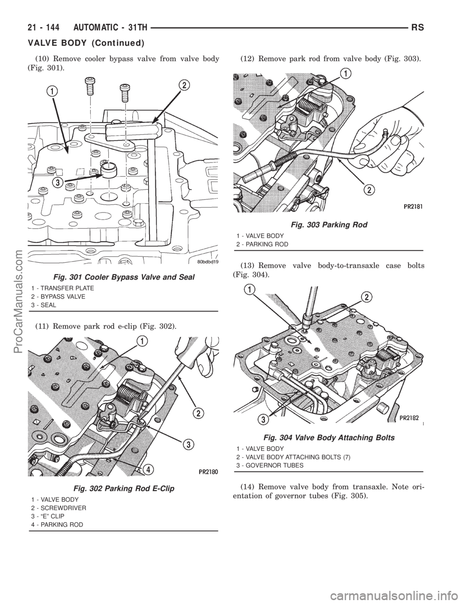
(10) Remove cooler bypass valve from valve body
(Fig. 301).
(11) Remove park rod e-clip (Fig. 302).(12) Remove park rod from valve body (Fig. 303).
(13) Remove valve body-to-transaxle case bolts
(Fig. 304).
(14) Remove valve body from transaxle. Note ori-
entation of governor tubes (Fig. 305).
Fig. 301 Cooler Bypass Valve and Seal
1 - TRANSFER PLATE
2 - BYPASS VALVE
3 - SEAL
Fig. 302 Parking Rod E-Clip
1 - VALVE BODY
2 - SCREWDRIVER
3 - ªEº CLIP
4 - PARKING ROD
Fig. 303 Parking Rod
1 - VALVE BODY
2 - PARKING ROD
Fig. 304 Valve Body Attaching Bolts
1 - VALVE BODY
2 - VALVE BODY ATTACHING BOLTS (7)
3 - GOVERNOR TUBES
21 - 144 AUTOMATIC - 31THRS
VALVE BODY (Continued)
ProCarManuals.com
Page 1642 of 2321
DISASSEMBLY
CAUTION: Do not clamp any portion of valve body
or transfer plate in a vise. Any slight distortion of
the aluminum body or transfer plate will result in
sticking valves, excessive leakage, or both. When
removing or installing valves or plugs, slide them in
or out carefully. Do not use force.
NOTE: TAG ALL SPRINGS AS THEY ARE REMOVED
FOR REASSEMBLY IDENTIFICATION.
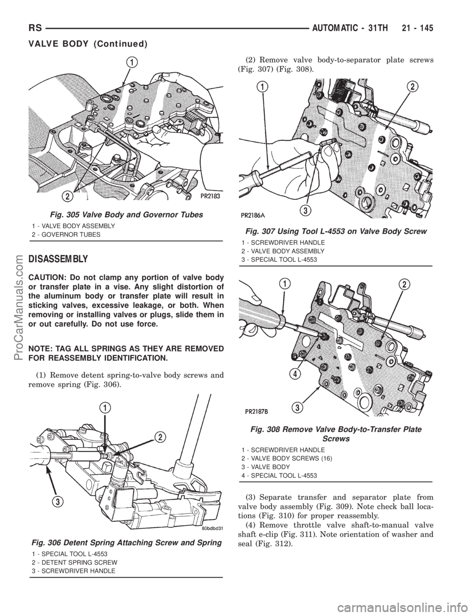
(1) Remove detent spring-to-valve body screws and
remove spring (Fig. 306).(2) Remove valve body-to-separator plate screws
(Fig. 307) (Fig. 308).
(3) Separate transfer and separator plate from
valve body assembly (Fig. 309). Note check ball loca-
tions (Fig. 310) for proper reassembly.
(4) Remove throttle valve shaft-to-manual valve
shaft e-clip (Fig. 311). Note orientation of washer and
seal (Fig. 312).
Fig. 305 Valve Body and Governor Tubes
1 - VALVE BODY ASSEMBLY
2 - GOVERNOR TUBES
Fig. 306 Detent Spring Attaching Screw and Spring
1 - SPECIAL TOOL L-4553
2 - DETENT SPRING SCREW
3 - SCREWDRIVER HANDLE
Fig. 307 Using Tool L-4553 on Valve Body Screw
1 - SCREWDRIVER HANDLE
2 - VALVE BODY ASSEMBLY
3 - SPECIAL TOOL L-4553
Fig. 308 Remove Valve Body-to-Transfer Plate
Screws
1 - SCREWDRIVER HANDLE
2 - VALVE BODY SCREWS (16)
3 - VALVE BODY
4 - SPECIAL TOOL L-4553
RSAUTOMATIC - 31TH21 - 145
VALVE BODY (Continued)
ProCarManuals.com
Page 1643 of 2321
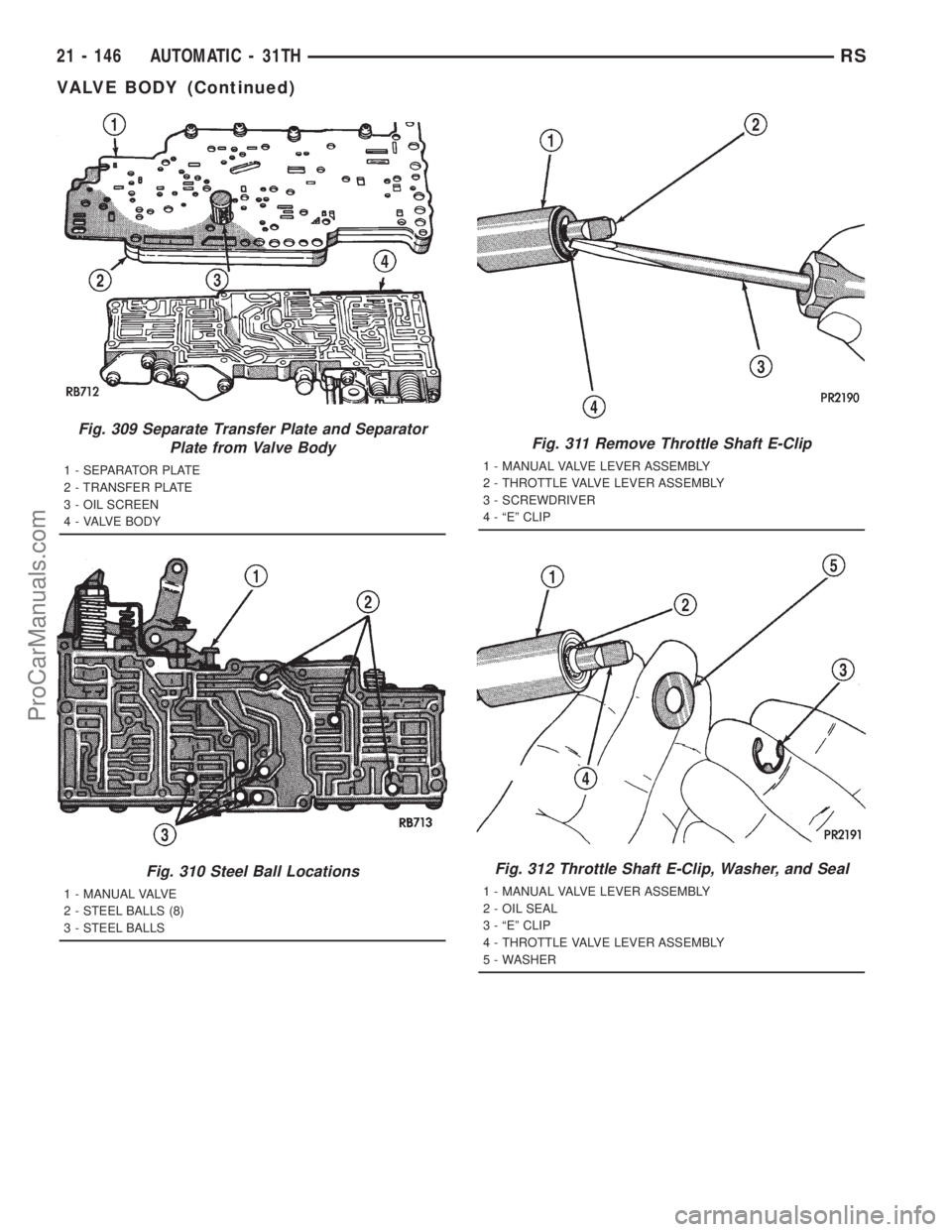
Fig. 309 Separate Transfer Plate and Separator
Plate from Valve Body
1 - SEPARATOR PLATE
2 - TRANSFER PLATE
3 - OIL SCREEN
4 - VALVE BODY
Fig. 310 Steel Ball Locations
1 - MANUAL VALVE
2 - STEEL BALLS (8)
3 - STEEL BALLS
Fig. 311 Remove Throttle Shaft E-Clip
1 - MANUAL VALVE LEVER ASSEMBLY
2 - THROTTLE VALVE LEVER ASSEMBLY
3 - SCREWDRIVER
4 - ªEº CLIP
Fig. 312 Throttle Shaft E-Clip, Washer, and Seal
1 - MANUAL VALVE LEVER ASSEMBLY
2 - OIL SEAL
3 - ªEº CLIP
4 - THROTTLE VALVE LEVER ASSEMBLY
5 - WASHER
21 - 146 AUTOMATIC - 31THRS
VALVE BODY (Continued)
ProCarManuals.com
Page 1644 of 2321
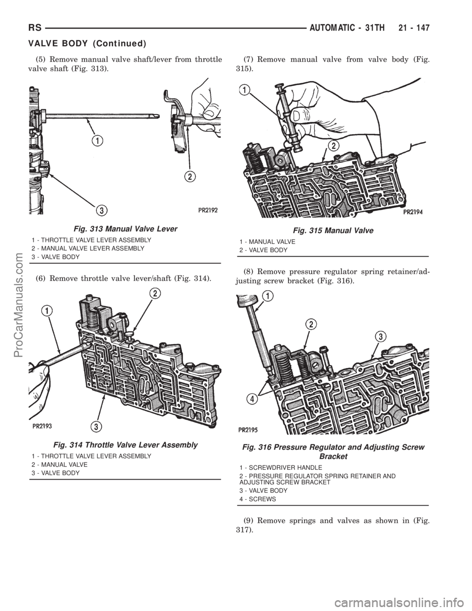
(5) Remove manual valve shaft/lever from throttle
valve shaft (Fig. 313).
(6) Remove throttle valve lever/shaft (Fig. 314).(7) Remove manual valve from valve body (Fig.
315).
(8) Remove pressure regulator spring retainer/ad-
justing screw bracket (Fig. 316).
(9) Remove springs and valves as shown in (Fig.
317).
Fig. 313 Manual Valve Lever
1 - THROTTLE VALVE LEVER ASSEMBLY
2 - MANUAL VALVE LEVER ASSEMBLY
3 - VALVE BODY
Fig. 314 Throttle Valve Lever Assembly
1 - THROTTLE VALVE LEVER ASSEMBLY
2 - MANUAL VALVE
3 - VALVE BODY
Fig. 315 Manual Valve
1 - MANUAL VALVE
2 - VALVE BODY
Fig. 316 Pressure Regulator and Adjusting Screw
Bracket
1 - SCREWDRIVER HANDLE
2 - PRESSURE REGULATOR SPRING RETAINER AND
ADJUSTING SCREW BRACKET
3 - VALVE BODY
4 - SCREWS
RSAUTOMATIC - 31TH21 - 147
VALVE BODY (Continued)
ProCarManuals.com
Page 1645 of 2321
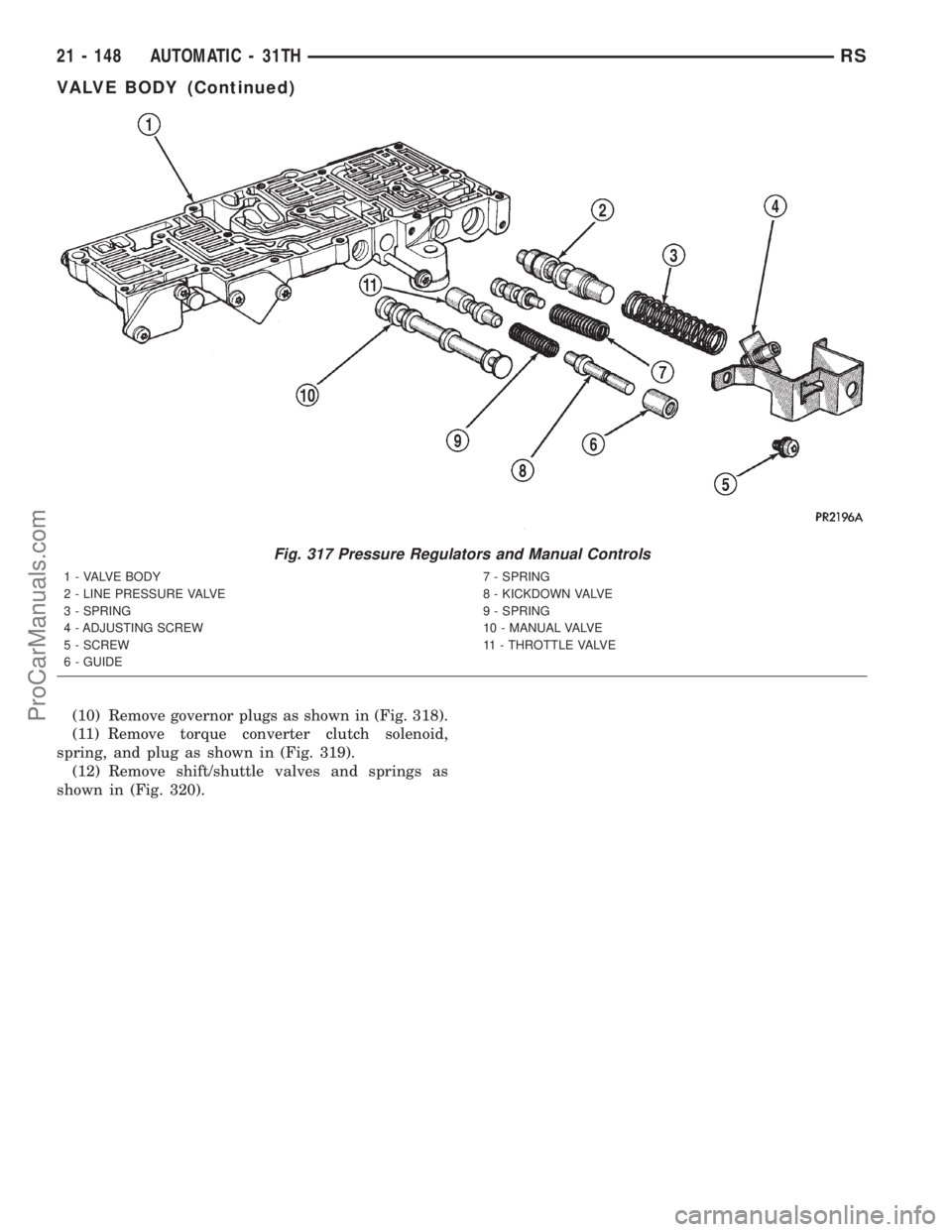
(10) Remove governor plugs as shown in (Fig. 318).
(11) Remove torque converter clutch solenoid,
spring, and plug as shown in (Fig. 319).
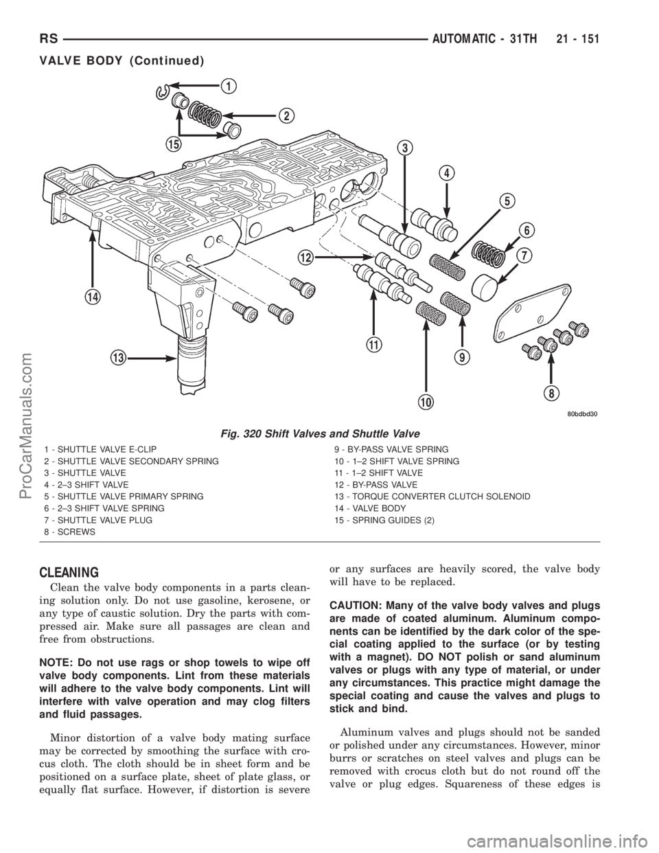
(12) Remove shift/shuttle valves and springs as
shown in (Fig. 320).
Fig. 317 Pressure Regulators and Manual Controls
1 - VALVE BODY
2 - LINE PRESSURE VALVE
3 - SPRING
4 - ADJUSTING SCREW
5 - SCREW
6 - GUIDE7 - SPRING
8 - KICKDOWN VALVE
9 - SPRING
10 - MANUAL VALVE
11 - THROTTLE VALVE
21 - 148 AUTOMATIC - 31THRS
VALVE BODY (Continued)
ProCarManuals.com
Page 1646 of 2321
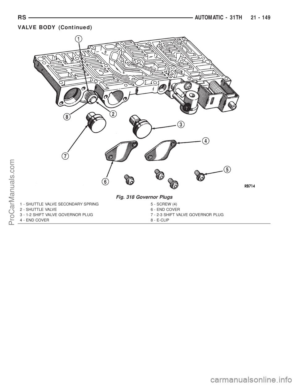
Fig. 318 Governor Plugs
1 - SHUTTLE VALVE SECONDARY SPRING
2 - SHUTTLE VALVE
3 - 1-2 SHIFT VALVE GOVERNOR PLUG
4 - END COVER5 - SCREW (4)
6 - END COVER
7 - 2-3 SHIFT VALVE GOVERNOR PLUG
8 - E-CLIP
RSAUTOMATIC - 31TH21 - 149
VALVE BODY (Continued)
ProCarManuals.com
Page 1647 of 2321
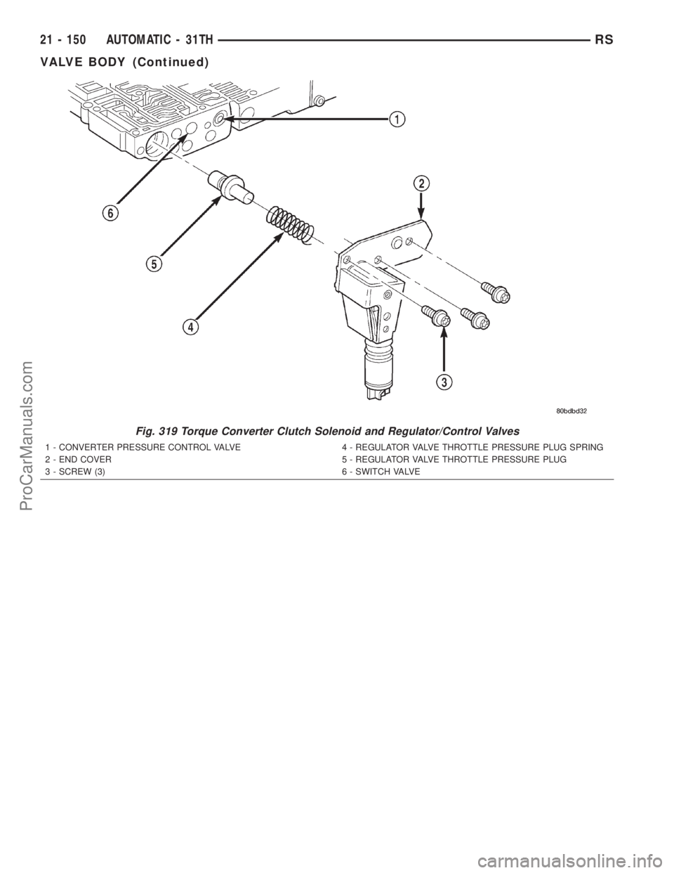
Fig. 319 Torque Converter Clutch Solenoid and Regulator/Control Valves
1 - CONVERTER PRESSURE CONTROL VALVE
2 - END COVER
3 - SCREW (3)4 - REGULATOR VALVE THROTTLE PRESSURE PLUG SPRING
5 - REGULATOR VALVE THROTTLE PRESSURE PLUG
6 - SWITCH VALVE
21 - 150 AUTOMATIC - 31THRS
VALVE BODY (Continued)
ProCarManuals.com
Page 1648 of 2321
CLEANING
Clean the valve body components in a parts clean-
ing solution only. Do not use gasoline, kerosene, or
any type of caustic solution. Dry the parts with com-
pressed air. Make sure all passages are clean and
free from obstructions.
NOTE: Do not use rags or shop towels to wipe off
valve body components. Lint from these materials
will adhere to the valve body components. Lint will
interfere with valve operation and may clog filters
and fluid passages.
Minor distortion of a valve body mating surface
may be corrected by smoothing the surface with cro-
cus cloth. The cloth should be in sheet form and be
positioned on a surface plate, sheet of plate glass, or
equally flat surface. However, if distortion is severeor any surfaces are heavily scored, the valve body
will have to be replaced.
CAUTION: Many of the valve body valves and plugs
are made of coated aluminum. Aluminum compo-
nents can be identified by the dark color of the spe-
cial coating applied to the surface (or by testing
with a magnet). DO NOT polish or sand aluminum
valves or plugs with any type of material, or under
any circumstances. This practice might damage the
special coating and cause the valves and plugs to
stick and bind.
Aluminum valves and plugs should not be sanded
or polished under any circumstances. However, minor
burrs or scratches on steel valves and plugs can be
removed with crocus cloth but do not round off the
valve or plug edges. Squareness of these edges is
Fig. 320 Shift Valves and Shuttle Valve
1 - SHUTTLE VALVE E-CLIP
2 - SHUTTLE VALVE SECONDARY SPRING
3 - SHUTTLE VALVE
4 - 2±3 SHIFT VALVE
5 - SHUTTLE VALVE PRIMARY SPRING
6 - 2±3 SHIFT VALVE SPRING
7 - SHUTTLE VALVE PLUG
8 - SCREWS9 - BY-PASS VALVE SPRING
10 - 1±2 SHIFT VALVE SPRING
11 - 1±2 SHIFT VALVE
1 2 - B Y- PA S S VA LV E
13 - TORQUE CONVERTER CLUTCH SOLENOID
14 - VALVE BODY
15 - SPRING GUIDES (2)
RSAUTOMATIC - 31TH21 - 151
VALVE BODY (Continued)
ProCarManuals.com
Page 1649 of 2321
vitally important. These edges prevent foreign matter
from lodging between the valves, plugs and bore.
INSPECTION
Inspect the throttle and manual valve levers and
shafts. Do not attempt to straighten a bent shaft or
correct a loose lever. Replace these components if
worn, bent, loose or damaged in any way.
Inspect all of the valve body mating surfaces for
scratches, nicks, burrs, or distortion. Use a straight-
edge to check surface flatness. Minor scratches may
be removed with crocus cloth using only very light
pressure.
Inspect the valves and plugs for scratches, burrs,
nicks, or scores. Also inspect the coating on the alu-
minum valves and plugs. If the coating is damaged
or worn through, the valve (or valve body) should be
replaced.
Inspect all the valve and plug bores in the valve
body. Use a penlight to view the bore interiors.
Replace the valve body if any bores are distorted or
scored. Inspect all of the valve body springs. The
springs must be free of distortion, warpage or broken
coils.
Trial fit each valve and plug in its bore to check
freedom of operation. When clean and dry, the valves
and plugs should drop freely into the bores. Valve
body bores do not change dimensionally with use. If
the valve body functioned correctly when new, it will
continue to operate properly after cleaning and
inspection. It should not be necessary to replace a
valve body assembly unless it is damaged in han-
dling.
ASSEMBLY
(1) Install shift/shuttle valves and springs as
shown in (Fig. 320).
(2) Install torque converter clutch solenoid, spring,
and plug as shown in (Fig. 319).
(3) Install governor plugs as shown in (Fig. 318).
(4) Install pressure regulator and manual control
springs and valves as shown in (Fig. 317).
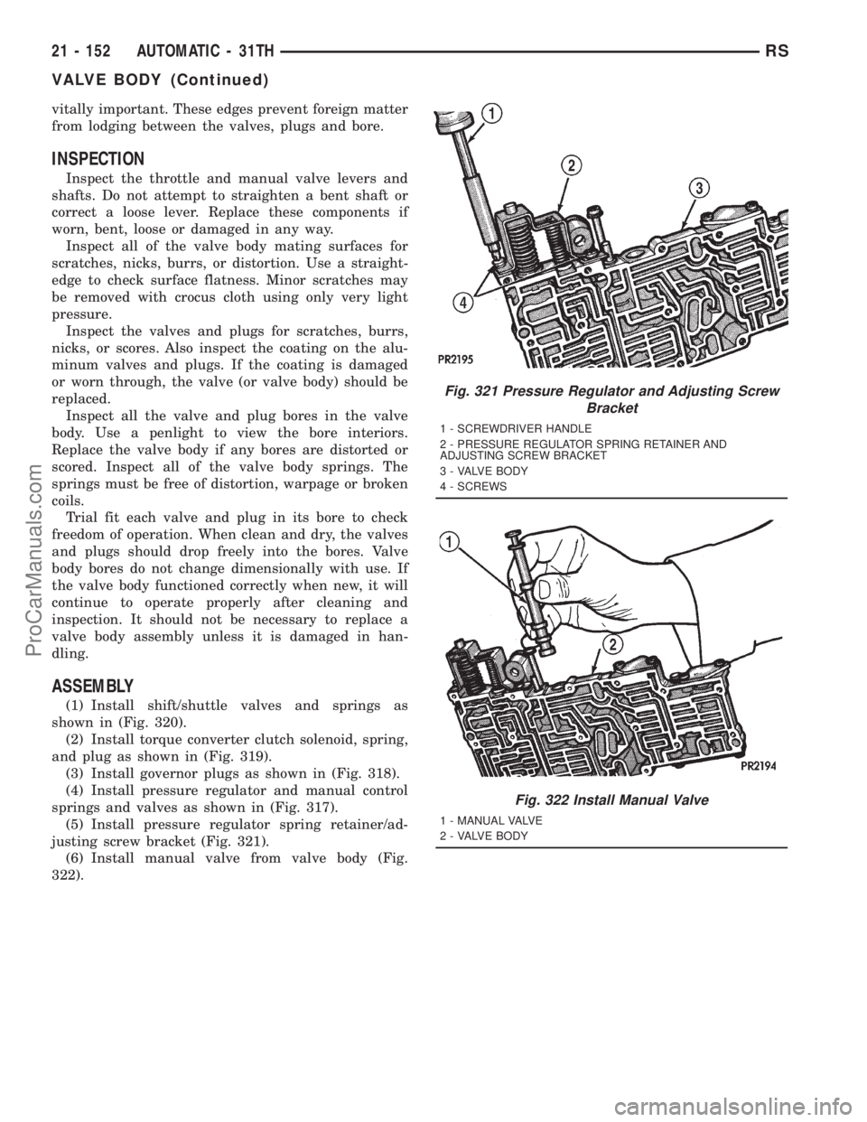
(5) Install pressure regulator spring retainer/ad-
justing screw bracket (Fig. 321).
(6) Install manual valve from valve body (Fig.
322).
Fig. 321 Pressure Regulator and Adjusting Screw
Bracket
1 - SCREWDRIVER HANDLE
2 - PRESSURE REGULATOR SPRING RETAINER AND
ADJUSTING SCREW BRACKET
3 - VALVE BODY
4 - SCREWS
Fig. 322 Install Manual Valve
1 - MANUAL VALVE
2 - VALVE BODY
21 - 152 AUTOMATIC - 31THRS
VALVE BODY (Continued)
ProCarManuals.com
Page 1650 of 2321
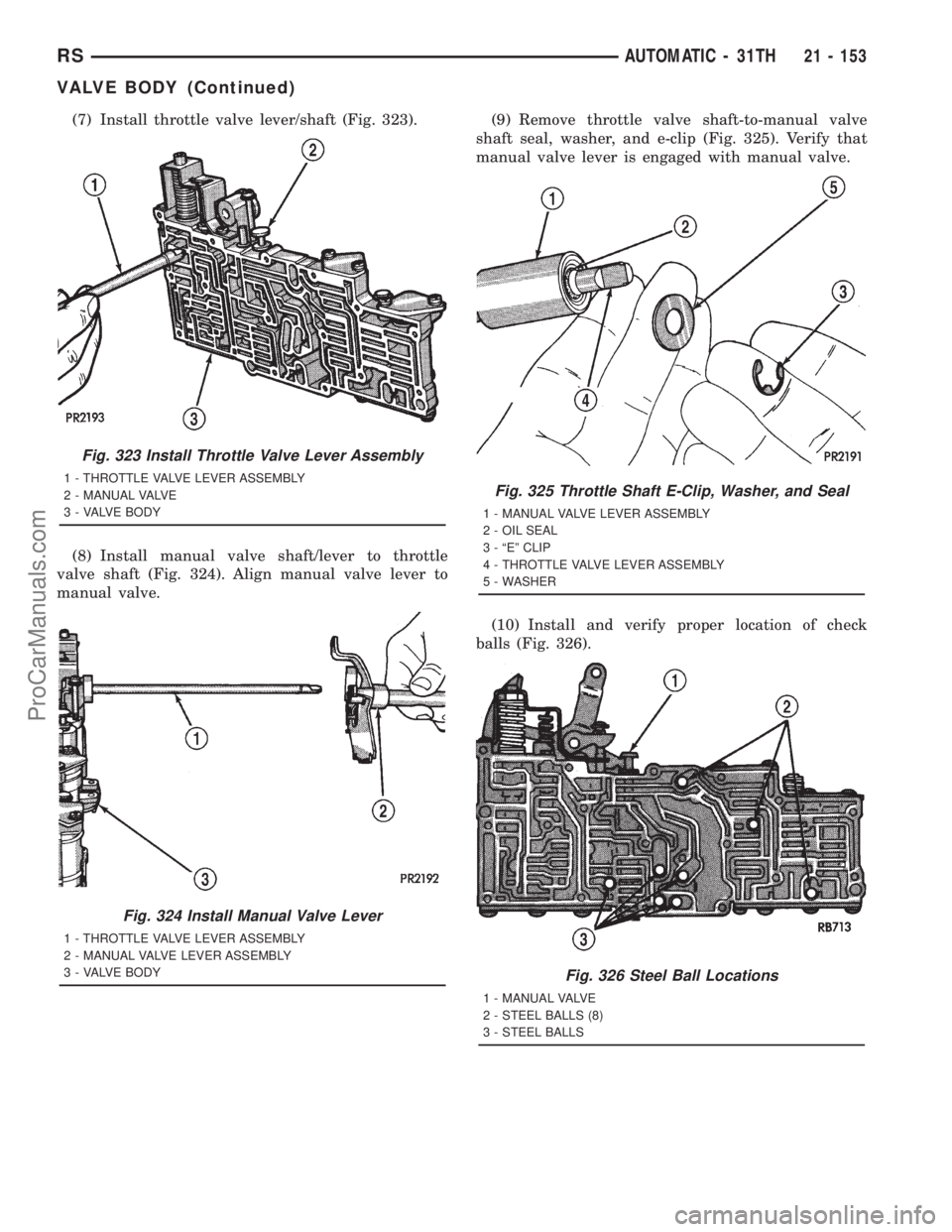
(7) Install throttle valve lever/shaft (Fig. 323).
(8) Install manual valve shaft/lever to throttle
valve shaft (Fig. 324). Align manual valve lever to
manual valve.(9) Remove throttle valve shaft-to-manual valve
shaft seal, washer, and e-clip (Fig. 325). Verify that
manual valve lever is engaged with manual valve.
(10) Install and verify proper location of check
balls (Fig. 326).
Fig. 323 Install Throttle Valve Lever Assembly
1 - THROTTLE VALVE LEVER ASSEMBLY
2 - MANUAL VALVE
3 - VALVE BODY
Fig. 324 Install Manual Valve Lever
1 - THROTTLE VALVE LEVER ASSEMBLY
2 - MANUAL VALVE LEVER ASSEMBLY
3 - VALVE BODY
Fig. 325 Throttle Shaft E-Clip, Washer, and Seal
1 - MANUAL VALVE LEVER ASSEMBLY
2 - OIL SEAL
3 - ªEº CLIP
4 - THROTTLE VALVE LEVER ASSEMBLY
5 - WASHER
Fig. 326 Steel Ball Locations
1 - MANUAL VALVE
2 - STEEL BALLS (8)
3 - STEEL BALLS
RSAUTOMATIC - 31TH21 - 153
VALVE BODY (Continued)
ProCarManuals.com