DODGE TRUCK 1993 Service Repair Manual
Manufacturer: DODGE, Model Year: 1993, Model line: TRUCK, Model: DODGE TRUCK 1993Pages: 1502, PDF Size: 80.97 MB
Page 1001 of 1502
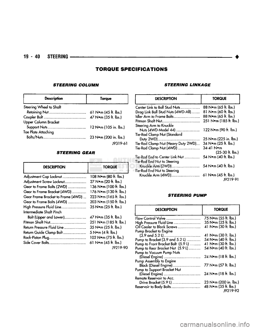
19-40
STEERING
•
TORQUE
SPECIFICATIONS
STEERING COLUMN STEERING LINKAGE
Description Torque
Steering Wheel to Shaft Retaining Nut 61 N»m (45 ft. lbs.)
Coupler Bolt 47 N»m (35 ft. lbs.) Upper Column Bracket
Support Nuts 12N*m(105in. lbs.)
Toe Plate Attaching
Bolts/Nuts 23 N«m (200 in. lbs.)
J9319-61
STEERING
GEAR
DESCRIPTION
TORQUE
Adjustment Cap Locknut 108 N»m (80 ft. lbs.)
Adjustment Screw Locknut.... 27 N®m (20 ft. lbs.)
Gear to Frame Bolts (2WD) 136
N®m
(100 ft. lbs.)
Gear to Frame Bracket (4WD) 176
N®m
(130 ft. lbs.)
Gear Frame Bracket to Frame (4WD)... 223 N*m (165 ft. lbs.)
Gear to Frame Bolts (4WD) 203 N*m (150 ft. lbs.)
High Pressure Fluid Line. 35 N*m (25 ft. lbs.)
Intermediate Shaft Pinch Bolt (Upper and Lower) 47 N»m (35 ft. lbs.)
Pitman Shaft Nut 251 N»m (185 ft. lbs.)
Return Pressure Fluid Line 35 N*m (25 ft. lbs.)
Return Guide Clamp Bolt 5 N*m (4 ft. lbs.)
Rack-Piston Plug 102
N®m
(75 ft. lbs.)
Side Cover Bolts 61 N*m (45 ft. lbs.) J9219-90
DESCRIPTION
TORQUE
Center Link to Ball Stud Nuts..., Drag Link Ball Stud Nuts (4WD-AII)
Idler Arm to Frame Bolts...
Pitman Shaft Nut
Steering Arm to Knuckle Nuts (4WD-Model 44)
Tie-Rod Clamp Nut (Standard
Duty 2WD)....
Tie-Rod Clamp Nut (Heavy Duty
2WD).
Tie-Rod Clamp Nut (4WD)
tie-Rod End to Center Link Nut.
Tie-Rod End Nut to Steering
Knuckle
Arm
(2WD)..
Tie-Rod End Nut to Steering Knuckle Arm (4WD) 88 N®m (65 ft. lbs.)
81 N®m (60 ft. lbs.)
88 N*m (65
ft.
lbs.) 251 NTn(185ft. lbs.)
122 N*m (90
ft.
lbs.)
25
N^m (225 in. lbs.)
34 N«m (25
ft.
lbs.)
34-41 N«m (25-30 ft. lbs.)
54 N«m (40
ft.
lbs.)
54 N*m (40
ft.
lbs.)
61 N«m(45ft. lbs.)
J9219-91
STEERING PUMP
DESCRIPTION
TORQUE
Flow Control Valve
High Pressure Fluid Line
Oil Cooler to Block Screws
Pump Bracket to Engine (3.9 and 5.2 L)..
Pump to Bracket (3.9 and 5.2
L)....
Pump to Front Bracket Bolt (5.9 L).
Pump to Rear Bracket Nut (5.9
L)
Pump to Vacuum Pump Nuts
(Diesel Engine)
Pump Assembly to Engine Block (Diesel Engine)
Pump to Support Bracket Nut (Diesel Engine)
Remote Reservoir to Acc, Drive Bracket (5.9
L)
Reservoir to Body Bolts 75 N®m (55
ft.
lbs.)
35 N«*m (25 ft. lbs.)
41 N*m (30
ft.
lbs.)
41 N*m (30
ft.
lbs.) 54 N®m (40
ft.
lbs.)
41 N*m (30
ft.
lbs.) 54 N*m (40
ft.
lbs.)
24 N®m
(18
ft.
lbs.)
77 N*m (57
ft.
lbs.) 24 NTH (18
ft.
lbs.)
23 N*m (200 in. lbs.)
48 N«m (35
ft.
lbs.) J9219-92
Page 1002 of 1502
•
TRANSMISSION
AND
TRANSFER
CASE
21 - 1
CONTENTS
page
AUTOMATIC
TRANSMISSI0N-32RH/36RH/
37RH/42RH/46RH
73
G360
MANUAL
TRANSMISSION
46
6360
TRANSMISSION
OVERHAUL
..........
53
NP2Q5
TRANSFER
CASE
................
342
page
NP241
TRANSFER
CASE
350
NV4500 MANUAL
TRANSMISSION
1
NV4500
TRANSMISSION
OVERHAUL
.........
6
TRANSMISSION/TRANSFER
CASE
SPECIFICATIONS
.....................
364
NV4300
MANUAL TRANSMISSION
INDEX
page
Gear Ratios
1
General
Information
1
Recommended
Lubricant—Capacity—Fill
Level
... 1
Shift
Pattern
1
Transmission Diagnosis
2
page
Transmission
Identification
1
Transmission
Installation—2-Wheel
Drive
4
Transmission
Installation—4-Wheel
Drive
........
5
Transmission
Removal—2-Wheel
Drive
3
Transmission
Removal—4-Wheel
Drive
4
GENERAL
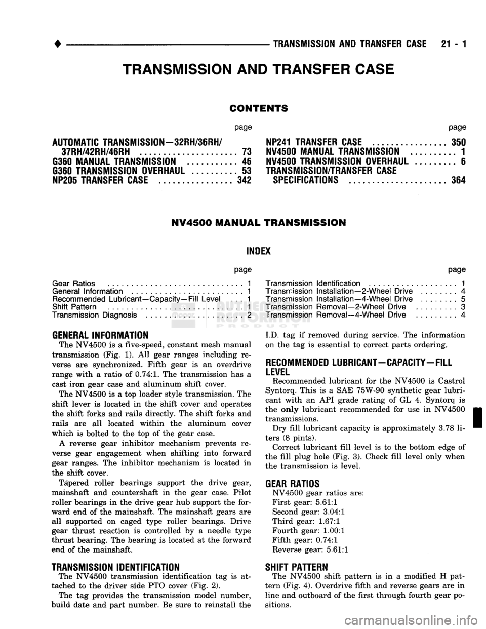
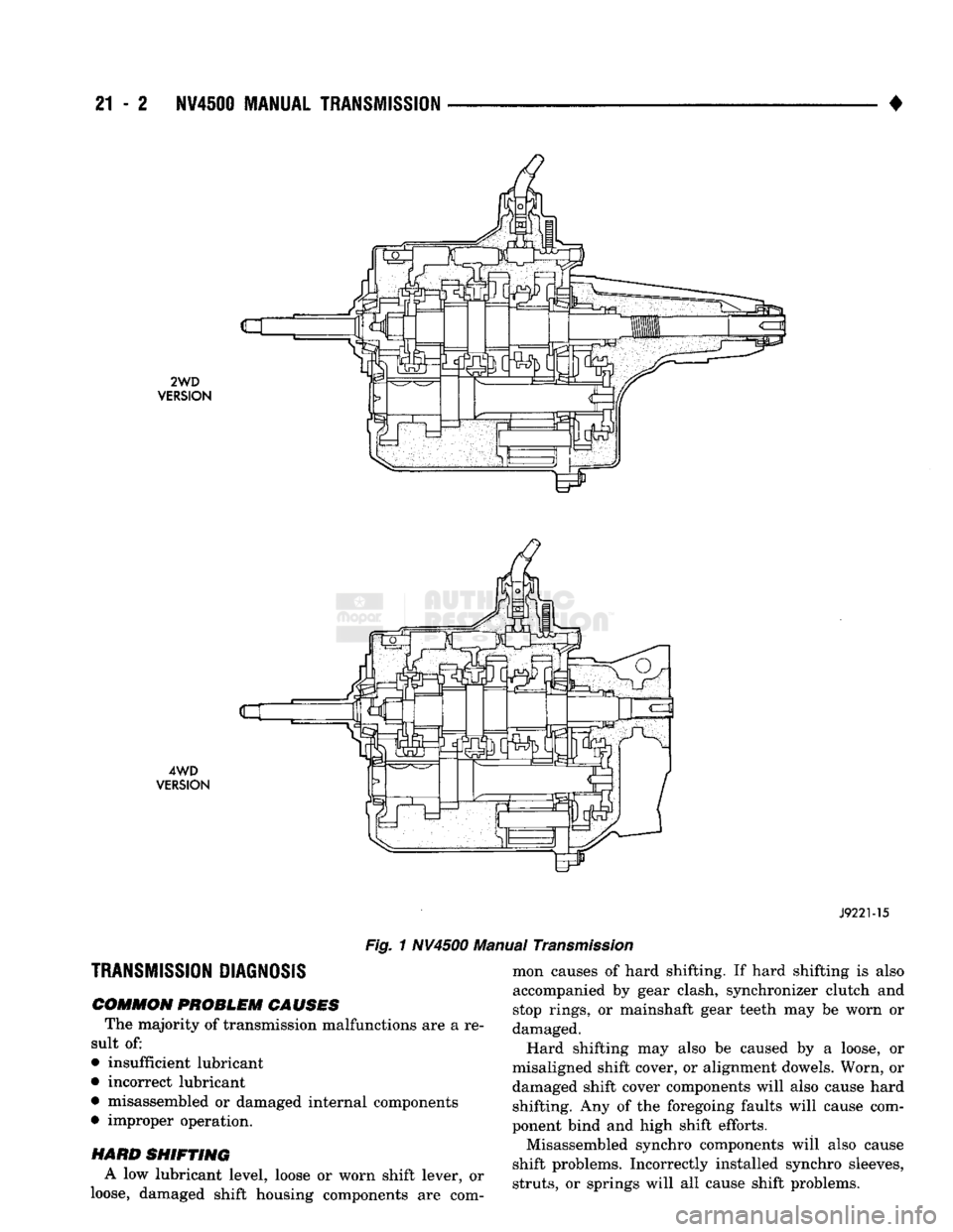
INFORMATION The NV4500
is a
five-speed, constant mesh manual
transmission (Fig.
1). All
gear ranges including
re
verse
are
synchronized. Fifth gear
is an
overdrive
range with
a
ratio
of
0.74:1.
The transmission has
a
cast iron gear case and aluminum shift cover. The NV4500
is a
top loader style transmission. The
shift lever
is
located
in the
shift cover and operates
the shift forks and rails directly. The shift forks and
rails
are all
located within
the
aluminum cover
which
is
bolted
to
the top
of
the gear case.
A reverse gear inhibitor mechanism prevents
re
verse gear engagement when shifting into forward
gear ranges. The inhibitor mechanism
is
located
in
the shift cover.
Tapered roller bearings support
the
drive gear,
mainshaft
and
countershaft
in the
gear case. Pilot
roller bearings
in
the drive gear hub support the for
ward end
of
the mainshaft. The mainshaft gears
are
all supported
on
caged type roller bearings. Drive
gear thrust reaction
is
controlled
by a
needle type
thrust bearing. The bearing
is
located
at
the forward
end
of
the mainshaft.
TRANSMISSION
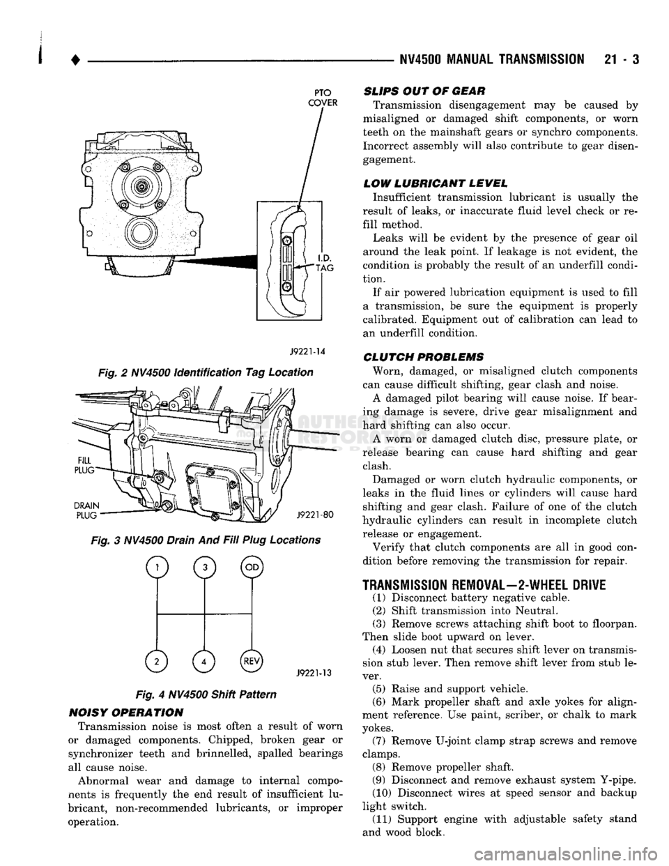
IDENTIFICATION The NV4500 transmission identification
tag is at
tached
to
the driver side PTO cover (Fig.
2).
The
tag
provides
the
transmission model number,
build date and part number.
Be
sure
to
reinstall
the
I.D.
tag if
removed during service. The information
on the tag
is
essential
to
correct parts ordering.
RECOMMENDED
LUBRICANT-CAPACITY-FILL
LEVEL
Recommended lubricant
for
the NV4500
is
Castrol
Syntorq. This
is a
SAE 75W-90 synthetic gear lubri
cant with
an
API grade rating
of
GL
4.
Syntorq
is
the only lubricant recommended
for
use
in
NV4500 transmissions. Dry fill lubricant capacity
is
approximately 3.78
li
ters
(8
pints). Correct lubricant fill level
is to
the bottom edge
of
the fill plug hole (Fig. 3). Check fill level only when
the transmission
is
level.
GEAR
RATIOS
NV4500 gear ratios are:
First gear:
5.61:1
Second gear: 3.04:1
Third gear:
1.67:1
Fourth gear:
1.00:1
Fifth gear: 0.74:1
Reverse gear:
5.61:1
SHIFT
PATTERN
The NV4500 shift pattern
is in a
modified
H
pat
tern (Fig. 4). Overdrive fifth and reverse gears are
in
line and outboard of the first through fourth gear po
sitions.
TRANSMISSION
AND
TRANSFER
CASE
Page 1003 of 1502
21
- 2
NV4500
MANUAL TRANSMISSION
•
2WD
VERSION
4WD
VERSION
J9221-15
Fig.
1 NV4500 Manual
Transmission
TRANSMISSION DIAGNOSIS
COMMON
PROBLEM CAUSES
The majority of transmission malfunctions are a re
sult of:
• insufficient lubricant
• incorrect lubricant
• misassembled or damaged internal components
• improper operation. mon causes of hard shifting. If hard shifting is also
accompanied by gear clash, synchronizer clutch and
stop rings, or mainshaft gear teeth may be worn or
damaged.
Hard shifting may also be caused by a loose, or
misaligned shift cover, or alignment dowels. Worn, or
damaged shift cover components will also cause hard shifting. Any of the foregoing faults will cause com
ponent bind and high shift efforts.
Misassembled synchro components will also cause
shift problems. Incorrectly installed synchro sleeves,
struts,
or springs will all cause shift problems.
HARD
SHIFTING
A low lubricant level, loose or worn shift lever, or
loose, damaged shift housing components are com
Page 1004 of 1502
•
NV4500 MANUAL
TRANSMISSION
21 - 3
PTO
COVER
J9221-14
Fig. 2 NV4500 identification Tag Location
DRAIN
PLUG
J9221-80
Fig. 3 NV4500 Drain And Fill Plug Locations
o
0 ©
0 0©
J9221-13
Fig. 4 NV4500 Shitt Pattern
NOISY OPERATION Transmission noise is most often a result of worn
or damaged components. Chipped, broken gear or
synchronizer teeth and brinnelled, spalled bearings
all cause noise.
Abnormal wear and damage to internal compo
nents is frequently the end result of insufficient lu
bricant, non-recommended lubricants, or improper operation.
SLIPS
OUT OF
GEAR
Transmission disengagement may be caused by
misaligned or damaged shift components, or worn
teeth on the mainshaft gears or synchro components. Incorrect assembly will also contribute to gear disengagement.
LOW LUBRICANT LEWEL
Insufficient transmission lubricant is usually the
result of leaks, or inaccurate fluid level check or re
fill method.
Leaks will be evident by the presence of gear oil
around the leak point. If leakage is not evident, the
condition is probably the result of an underfill condi
tion.
If air powered lubrication equipment is used to fill
a transmission, be sure the equipment is properly
calibrated. Equipment out of calibration can lead to
an underfill condition.
CLUTCH
PROBLEMS
Worn, damaged, or misaligned clutch components
can cause difficult shifting, gear clash and noise.
A damaged pilot bearing will cause noise. If bear
ing damage is severe, drive gear misalignment and
hard shifting can also occur.
A worn or damaged clutch disc, pressure plate, or
release bearing can cause hard shifting and gear clash.
Damaged or worn clutch hydraulic components, or
leaks in the fluid lines or cylinders will cause hard shifting and gear clash. Failure of one of the clutch
hydraulic cylinders can result in incomplete clutch release or engagement.
Verify that clutch components are all in good con
dition before removing the transmission for repair.
TRANSMISSION
REMOVAL—2-WHEEL DRIVE
(1) Disconnect battery negative cable. (2) Shift transmission into Neutral.
(3) Remove screws attaching shift boot to floorpan.
Then slide boot upward on lever. (4) Loosen nut that secures shift lever on transmis
sion stub lever. Then remove shift lever from stub le
ver. (5) Raise and support vehicle.
(6) Mark propeller shaft and axle yokes for align
ment reference. Use paint, scriber, or chalk to mark
yokes.
(7) Remove U-joint clamp strap screws and remove
clamps. (8) Remove propeller shaft.
(9) Disconnect and remove exhaust system Y-pipe.
(10) Disconnect wires at speed sensor and backup
light switch. (11) Support engine with adjustable safety stand
and wood block.
Page 1005 of 1502
21
- 4
NV4500 MANUAL TRANSMISSION
(12) If transmission is to be disassembled for re
pair, remove drain plug and drain lubricant from transmission.
(13) move bolts/nuts attaching transmission to rear
mount.
(14) Support transmission with a transmission
jack. Secure transmission to jack with safety chains.
(15) Remove rear crossmember,
(16) Remove bolts attaching clutch slave cylinder
to clutch housing. Then move cylinder aside for
working clearance.
(17) Remove transmission harness wires from clips
on transmission shift cover. (18) Remove bolts attaching transmission to clutch
housing. (19) Slide transmission and jack rearward until
drive gear clears clutch housing. (20) Lower transmission jack and remove trans
mission from under vehicle. (21) If transmission will be overhauled, clean
transmission exterior with solvent or with steam gun.
TRANSMISSION
INSTALLATION—2-WHEEL DRIVE
(1) Apply light coat of Mopar high temperature
bearing grease to contact surfaces of following com
ponents: • drive gear splines and pilot bearing hub
• release bearing slide surface of front retainer
• pilot bearing • release bearing bore
• release fork
• release fork ball stud
• propeller shaft slip yoke (2) Fill transmission with recommended lubricant.
Correct fill level is bottom edge of fill plug hole. (3) Mount transmission on jack and position trans
mission under vehicle. (4) Raise transmission until drive gear is centered
in release bearing and clutch disc hub. (5) Move transmission forward and start drive gear
in release bearing, clutch disc and pilot bushing. (6) Work transmission forward until seated against
clutch housing. Do not allow transmission to remain
unsupported after drive gear has entered clutch disc. (7) Install and tighten transmission-to-clutch hous
ing bolts to 108 N*m (80 ft. lbs.) torque. (8) Install clutch slave cylinder. (9) Connect speed sensor and backup light switch
wires.
(10) Position transmission harness wires in clips
on shift cover. (11) Install transmission mount on transmission or
rear crossmember. (12) Install rear crossmember.
(13) Remove transmission jack and engine support
fixture. (14) Align and connect propeller shaft. (15) Fill transmission with required lubricant, if
necessary. (16) Lower vehicle.
(17) Install shift lever on transmission stub lever.
(18) Install shift boot and bezel. (19) Connect battery negative cable.
TRANSMISSION REMOVAL—4-WHEEL DRIVE
(1) Disconnect battery negative cable.
(2) Shift transmission into Neutral.
(3) Remove shift lever boot and bezel. (4) Loosen nut attaching shift lever to transmis
sion stub lever and remove shift lever from stub le
ver. (5) Raise- vehicle.
(6) Remove skid plate if equipped.
(7) If transmission will be disassembled for repair,
remove drain plug and drain lubricant from trans
mission. (8) Mark propeller shafts and yokes for assembly
reference. (9) Disconnect propeller shafts and remove propel
ler shafts. (10) Disconnect and remove exhaust system
Y-pipe. Then disconnect and lower remaining ex
haust pipes for clearance as necessary. (11) Support engine with adjustable safety stand.
(12) Disconnect speed sensor wires and disconnect
speedometer cable, if equipped. (13) Disconnect backup light switch wires.
(14) Disconnect transfer case shift linkage at
transfer case range lever. (15) Remove bolts/nuts attaching transmission to
rear support. (16) Remove crossmember bolts/nuts and remove
crossmember. (17) Support transfer case with transmission jack.
Secure transfer case to jack with safety chains. (18) Remove transfer case attaching nuts.
(19) Move transfer case rearward until input gear
clears transmission mainshaft. (20) Lower transfer case assembly and move it
from under vehicle. (21) If transmission is being removed for repair,
remove drain plug and drain lubricant from trans mission.
(22) Support transmission with transmission jack.
Secure transmission to jack with safety chains.
(23) Remove transmission harness from retaining
clips on transmission shift cover. (24) Remove bolts/nuts attaching transmission
mount to rear crossmember.
(25) Remove rear crossmember.
(26) Remove clutch slave cylinder splash shield, if
equipped.
(27) Loosen clutch slave cylinder attaching nuts
until cylinder piston rod is clear of release lever.
This reduces pressure on lever and release bearing
Page 1006 of 1502
1
.
NW4500
MANUAL
TRANSMISSION 21 - 5 making transmission removal/installation easier.
Cylinder does not have to be removed completely. (28) Remove bolts attaching transmission to clutch
housing.
(29) Move transmission rearward until drive pin
ion clears clutch disc and release bearing. (30) Lower transmission and remove it from under
vehicle.
(31) If transmission will be overhauled, thoroughly
clean transmission exterior with solvent or steam
gun.
TRANSMISSION INSTALLATION-4-WHEEL DRIVE (1) Apply light coat of Mopar high temperature
bearing grease to contact surfaces of following com
ponents: • drive gear splines and pilot bearing hub • release bearing slide surface of front retainer
• pilot bearing
• release bearing bore
• release fork
• release fork ball stud
• propeller shaft slip yoke (2) Fill transmission with recommended lubricant.
Correct level is to bottom edge of fill plug hole. (3) Mount transmission on jack and position trans
mission under vehicle. Secure transmission to jack
with safety chains. (4) Raise transmission until drive gear is centered
in release bearing and clutch disc hub. (5) Move transmission forward and start drive gear
in release bearing and clutch disc. (6) Work transmission forward until seated against
clutch housing. Do not allow transmission to remain
unsupported after drive gear has entered clutch disc. (7) Install and tighten transmission-to-clutch hous
ing bolts to 108 N*m (80 ft. lbs.) torque. (8) Connect speed sensor and backup light switch
wires.
(9) Position transmission harness wires in clips on
shift cover. (10) Tighten slave cylinder attaching nuts and in
stall slave cylinder shield, if equipped.
(11) Install transmission mount on transmission or
rear crossmember. (12) Install rear crossmember.
(13) Remove transmission jack and engine support
fixture.
(14) Install transfer case on transmission jack. Se
cure transfer case to jack with safety chains. (15) Install new gasket on transmission adapter, or
coat adapter sealing surface with Mopar Gasket
Maker, or silicone adhesive sealer.
(16) Raise jack and align transfer case input gear
with transmission mainshaft.
(17) Move transfer case forward and seat it on
adapter.
(18) Install and tighten transfer case attaching
nuts to 47 N«m (35 ft. lbs.) torque.
(19) Connect transfer case shift lever to range le
ver on transfer case. (20) Align and connect propeller shafts. Tighten
U-joint clamp strap bolts to 19 N*m (170 in. lbs.)
torque.
(21) Check lubricant levels in transmission and
transfer case. Add lubricant if necessary.
(22) Install transfer case skid plate and crossmem
ber. Tighten attaching bolts/nuts to 41 N»m (30 ft. lbs.) torque.
(23) Install exhaust system components.
(24) Lower vehicle.
(25) Install transmission shift lever, boot and be
zel.
(26) Connect battery negative cable.
Page 1007 of 1502
21
- i NV4500
TRANSMISSION OVERHAUL
NV4500
TRANSMISSION
OVERHAUL
INDEX
page
Shift
Cover Service
....................... 43
Transmission Assembly
and
Adjustment
....... 26
TRANSMISSION DISASSEMBLY
SHIFT
COVER REMOVAL
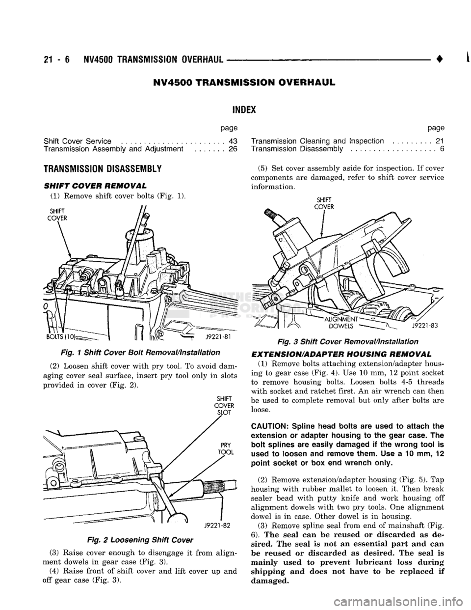
(1) Remove shift cover bolts (Fig. 1).
Fig.
1 Shift
Cower
Bolt
Removal/installation
(2)
Loosen shift cover with pry tool. To avoid dam
aging cover seal surface, insert pry tool only in slots
provided in cover (Fig. 2).
SHIFT
COVER SLOT
Fig.
2
Loosening
Shift
Cover
(3)
Raise cover enough to disengage it from align
ment dowels in gear case (Fig. 3).
(4)
Raise front of shift cover and lift cover up and
off gear case (Fig. 3).
page
Transmission Cleaning
and
Inspection
......... 21
Transmission Disassembly
6
(5)
Set cover assembly aside for inspection. If cover
components are damaged, refer to shift cover service
information.
SHIFT
COVER
Fig.
3 Shift
Cover
Removal/installation
EXTENSION/ADAPTER HOUSING REMOVAL
(1)
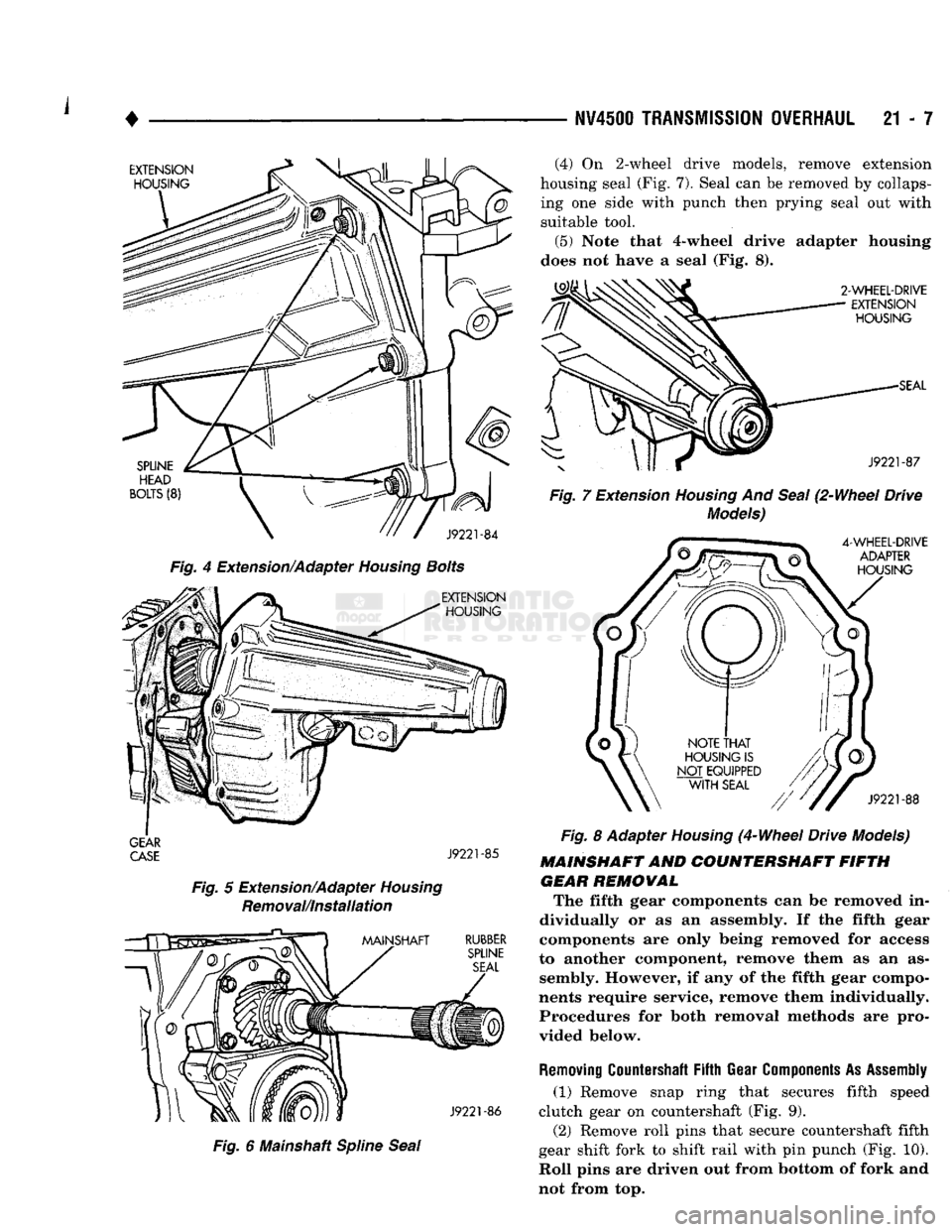
Remove bolts attaching extension/adapter hous
ing to gear case (Fig. 4). Use 10 mm, 12 point socket
to remove housing bolts. Loosen bolts 4-5 threads
with socket and ratchet first. An air wrench can then
be used to complete removal but only after bolts are loose.
CAUTION:
Spline head bolts
are
used
to
attach
the
extension
or
adapter housing
to the
gear
case.
The
bolt splines
are
easily damaged
if the
wrong
tool
is
used
to
loosen
and
remove them.
Use a 10 mm, 12
point socket
or box end
wrench only.
(2)
Remove extension/adapter housing (Fig. 5). Tap
housing with rubber mallet to loosen it. Then break sealer bead with putty knife and work housing off
alignment dowels with two pry tools. One alignment
dowel is in case. Other dowel is in housing.
(3)
Remove spline seal from end of mainshaft (Fig.
6).
The seal can be reused or discarded as de
sired. The seal is not an essential part and can
be reused or discarded as desired. The seal is
mainly used to prevent lubricant loss during shipping and does not have to be replaced if damaged.
Page 1008 of 1502
NV4500
TRANSMISSION
OVERHAUL
21 - 7
EXTENSION
HOUSING
SPLINE
HEAD
BOLTS
(8)
J9221-84
Fig. 4 Extension/Adapter
Housing
Bolts
EXTENSION
HOUSING
GEAR
CASE
J9221-85
Fig.
5 Extension/Adapter
Housing
Removal/Installation
MAINSHAFT
RUBBER
SPLINE
SEAL
J9221-86
Fig.
6 Mainshaft
Spline
Seal
(4)
On 2-wheel drive models, remove extension
housing seal (Fig. 7). Seal can be removed by collaps ing one side with punch then prying seal out with
suitable tool.
(5) Note that 4-wheel drive adapter housing
does not have a seal (Fig. 8).
2-WHEEL-DRIVE
EXTENSION
HOUSING
SEAL
J9221-87
Fig.
7 Extension
Housing
And
Seal
(2-Wheel Drive
Models)
4-WHEEL-DRIVE
ADAPTER
HOUSING
J9221-88
Fig.
8 Adapter
Housing
(4-Wheel Drive Models)
MAINSHAFT AND COUNTERSHAFT FIFTH GEAR REMOWAL The fifth gear components can be removed in
dividually or as an assembly. If the fifth gear
components are only being removed for access
to another component, remove them as an as sembly. However, if any of the fifth gear compo
nents require service, remove them individually. Procedures for both removal methods are pro
vided below.
Removing
Countershaft
Fifth
Gear
Components
As
Assembly
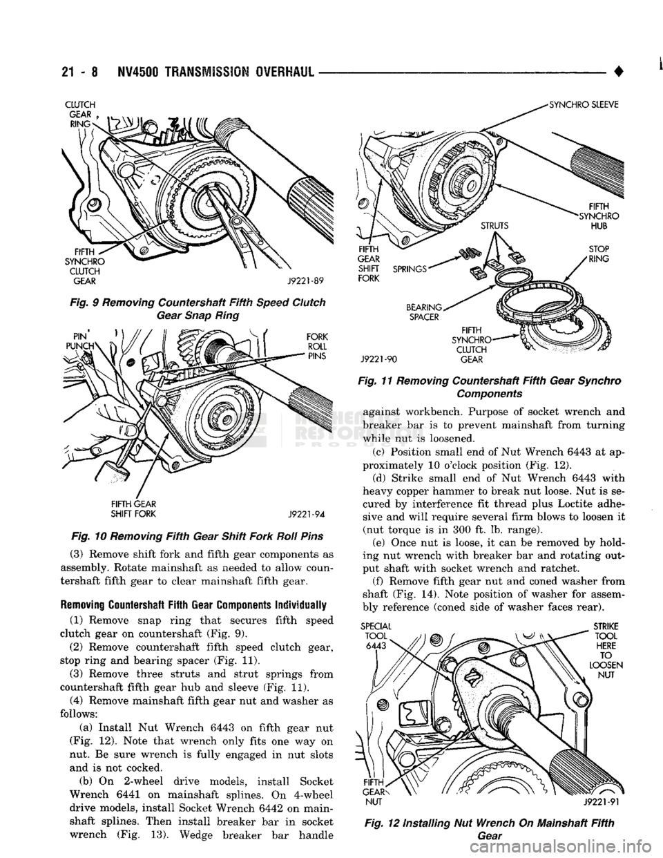
(1) Remove snap ring that secures fifth speed
clutch gear on countershaft (Fig. 9). (2) Remove roll pins that secure countershaft fifth
gear shift fork to shift rail with pin punch (Fig. 10).
Roll pins are driven out from bottom of fork and
not from top.
Page 1009 of 1502
21
- 8
NV4500
TRANSMISSION OVERHAUL
———— ^ ____ - #
CLUTCH
GEAR J9221-89
Fig. 9 Removing Countershaft Fifth Speed Clutch Gear Snap Ring
FIFTH GEAR
SHIFT FORK
J9221-94
Fig. 10 Removing Fifth Gear Shift Fork Roil Pins
(3) Remove shift fork and fifth gear components as
assembly. Rotate mainshaft as needed to allow coun
tershaft fifth gear to clear mainshaft fifth gear.
Removing
Countershaft
Fifth
Gear
Components
Individually
(1) Remove snap ring that secures fifth speed
clutch gear on countershaft (Fig. 9). (2) Remove countershaft fifth speed clutch gear,
stop ring and bearing spacer (Fig. 11).
(3) Remove three struts and strut springs from
countershaft fifth gear hub and sleeve (Fig. 11). (4) Remove mainshaft fifth gear nut and washer as
follows:
(a) Install Nut Wrench 6443 on fifth gear nut
(Fig. 12). Note that wrench only fits one way on
nut. Be sure wrench is fully engaged in nut slots and is not cocked.
(b) On 2-wheel drive models, install Socket
Wrench 6441 on mainshaft splines. On 4-wheel drive models, install Socket Wrench 6442 on main-
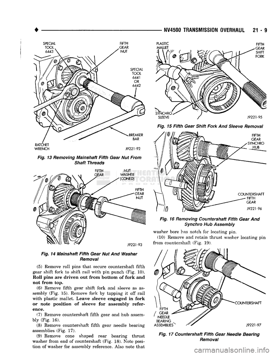
shaft splines. Then install breaker bar in socket wrench (Fig. 13). Wedge breaker bar handle
J9221-90
GEAR
Fig. 11 Removing Countershaft Fifth Gear Synchro Components against workbench. Purpose of socket wrench and
breaker bar is to prevent mainshaft from turning
while nut is loosened.
(c) Position small end of Nut Wrench 6443 at ap
proximately 10 o'clock position (Fig. 12).
(d) Strike small end of Nut Wrench 6443 with
heavy copper hammer to break nut loose. Nut is se
cured by interference fit thread plus Loctite adhe sive and will require several firm blows to loosen it
(nut torque is in 300 ft. lb. range). (e) Once nut is loose, it can be removed by hold
ing nut wrench with breaker bar and rotating out
put shaft with socket wrench and ratchet.
(f)
Remove fifth gear nut and coned washer from
shaft (Fig. 14). Note position of washer for assem
bly reference (coned side of washer faces rear). SPECIAL
STRIKE
NUT J9221-91
Fig. 12 installing Nut Wrench On Mainshaft Fifth Gear
Page 1010 of 1502
NV4500
TRANSMISSION
OVERHAUL
21 - I
SPECIAL FIFTH
RATCHET
WRENCH J9221-92
Fig. 13 Removing Mainshaft Fifth Gear Nut From Shaft Threads
FIFTH
NUT
Fig. 14 Mainshaft Fifth Gear Nut And Washer Removal (5) Remove roll pins that secure countershaft fifth
gear shift fork to shift rail with pin punch (Fig. 10).
Roll pins are driven out from
bottom
of fork and
not from top.
(6) Remove fifth gear shift fork and sleeve as as
sembly (Fig. 15). Remove fork by tapping it off rail
with plastic mallet. Leave sleeve engaged in fork or note position of sleeve for assembly refer
ence.
(7) Remove countershaft fifth gear and hub assem
bly (Fig. 16). (8) Remove countershaft fifth gear needle bearing
assemblies (Fig. 17). (9) Remove cone shaped rear bearing thrust
washer from end of countershaft (Fig. 18). Note posi
tion of washer for assembly reference. Also note that
PLASTIC FIFTH
Fig. 15 Fifth Gear Shift Fork And Sleeve Removal
Fig. 16 Removing Countershaft Fifth Gear And Synchro Hub Assembly washer bore has notch for locating pin.
(10) Remove and retain thrust washer locating pin
from countershaft (Fig. 19). Fig. 17 Countershaft Fifth Gear Needle Bearing
Removal