DODGE TRUCK 1993 Service Repair Manual
Manufacturer: DODGE, Model Year: 1993, Model line: TRUCK, Model: DODGE TRUCK 1993Pages: 1502, PDF Size: 80.97 MB
Page 971 of 1502
19
- 10
STEERING
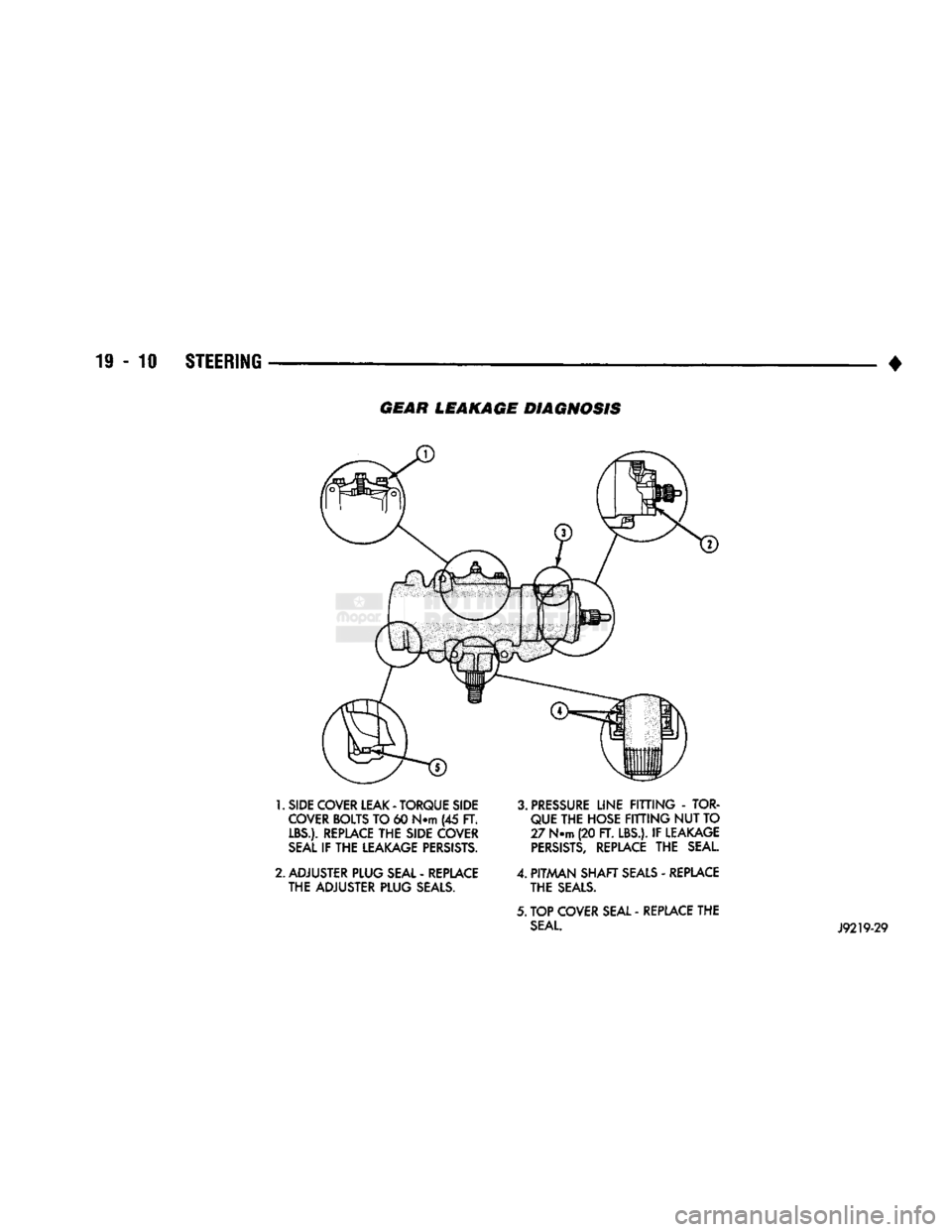
• GEAR LEAKAGE DIAGNOSIS
1.
SIDE COVER LEAK
-
TORQUE SIDE COVER BOLTS
TO 60
NTTI
(45 FT.
LBS.). REPLACE
THE
SIDE COVER
SEAL
IF THE
LEAKAGE PERSISTS.
2.
ADJUSTER PLUG SEAL
-
REPLACE
THE
ADJUSTER PLUG SEALS.
3.
PRESSURE
LINE
FITTING - TOR
QUE THE
HOSE
FITTING NUT TO
27
N.m
(20
FT. LBS.).
IF
LEAKAGE
PERSISTS,
REPLACE
THE
SEAL.
4.
PITMAN
SHAFT
SEALS
-
REPLACE
THE SEALS.
5. TOP
COVER SEAL
-
REPLACE
THE
SEAL. J9219-29
Page 972 of 1502
•
STEERING
19 - 11
POWER STEERING PUMP
INDEX
page
Power
Steering
Hose
11
Power
Steering Pump—Initial Operation
15
Pump
Pulley
15
Pump
Replacement—Diesel Engine
12
SERVICE
INFORMATION
The power steering pump internal components are
not serviced or adjusted. If a malfunction or an inter
nal fluid leak occurs, the complete unit must be re
placed.
POWER
STEERING HOSE
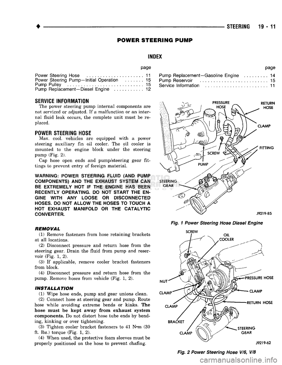
Max. cool, vehicles are equipped with a power
steering auxiliary fin oil cooler. The oil cooler is
mounted to the engine block under the steering
pump (Fig. 2). Cap hose open ends and pump/steering gear fit
tings to prevent entry of foreign material.
WARNING; POWER STEERING
FLUID
(AND
PUMP
COMPONENTS)
AND THE
EXHAUST SYSTEM
CAN
BE EXTREMELY
HOT IF THE
ENGINE
HAS
BEEN
RECENTLY OPERATING.
DO NOT
START
THE EN
GINE WITH
ANY
LOOSE
OR
DISCONNECTED
HOSES.
DO
NOT
ALLOW
THE
HOSES
TO
TOUCH
A
HOT EXHAUST
MANIFOLD
OR THE
CATALYTIC
CONVERTER.
REMOWAL (1) Remove fasteners from hose retaining brackets
at all locations. (2) Disconnect pressure and return hose from the
steering gear. Drain the fluid from pump and reser
voir (Fig. 1, 2).
(3) If applicable, remove cooler bracket fasteners
from block. (4) Disconnect pressure and return hose from the
pump. Remove hoses from vehicle (Fig. 1, 2).
INSTALLATION
(1) Wipe hose ends, pump and gear unions clean.
(2) Connect hose at steering gear and pump. Route
hose while avoiding extreme bends or kinks. The
hose must be kept away from exhaust system components. Do not distort hose tube ends by bend
ing, kinking or over tightening.
(3) Tighten cooler bracket fasteners to 41 N»m (30
ft. lbs.) torque (Fig. 1, 2). (4) When used, the protective foam sleeves must be
properly positioned on the hose to prevent chafing. page
Pump
Replacement—Gasoline Engine
......... 14
Pump
Reservoir
15
Service
Information
....................... 11
Fig.
1
Power
Steering
Hose Diesel Engine
SCREW
Fig.
2
Power
Steering
Hose
V/6, V/8
Page 973 of 1502
19
- 12
STEERING
• (5) Tighten fittings at pump and gear to 35 Nnn
(25 ft. lbs.) torque.
(6)
Install clamps on return hose on gear and
pump.
(7)
After installation, inspect and test for fluid
leaks.
PUMP REPLACEMENT—DIESEL ENGINE
REMOVAL
(1) Place a drain pan under the power steering
pump.
(2) Disconnect and cap the vacuum and steering
pump hoses.
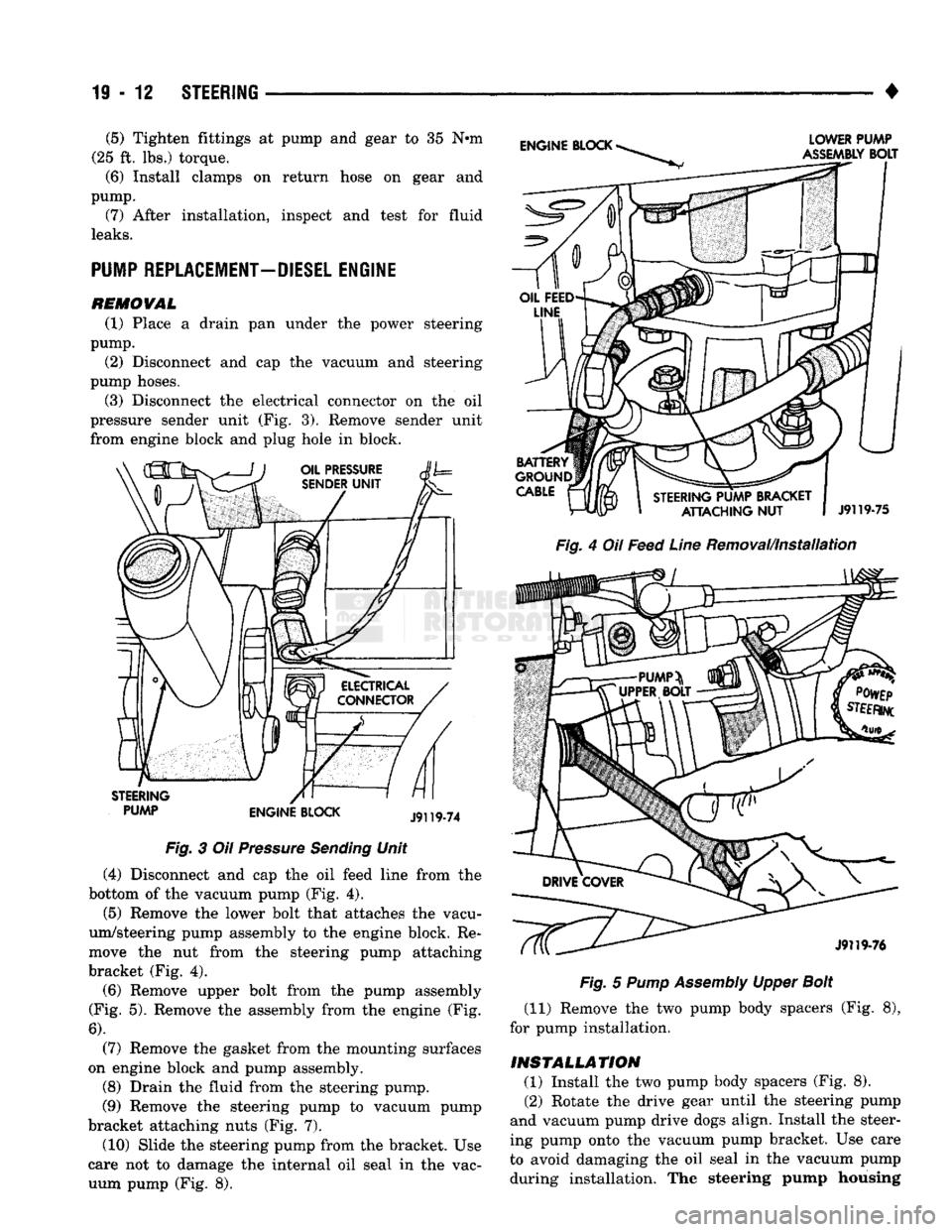
(3) Disconnect the electrical connector on the oil
pressure sender unit (Fig. 3). Remove sender unit
from engine block and plug hole in block.
PUMP ENGINE BLOCK Fig.
3 Oil
Pressure
Sending
Unit
(4) Disconnect and cap the oil feed line from the
bottom of the vacuum pump (Fig. 4). (5) Remove the lower bolt that attaches the vacu
um/steering pump assembly to the engine block. Re
move the nut from the steering pump attaching
bracket (Fig. 4).
(6)
Remove upper bolt from the pump assembly
(Fig. 5). Remove the assembly from the engine (Fig.
6).
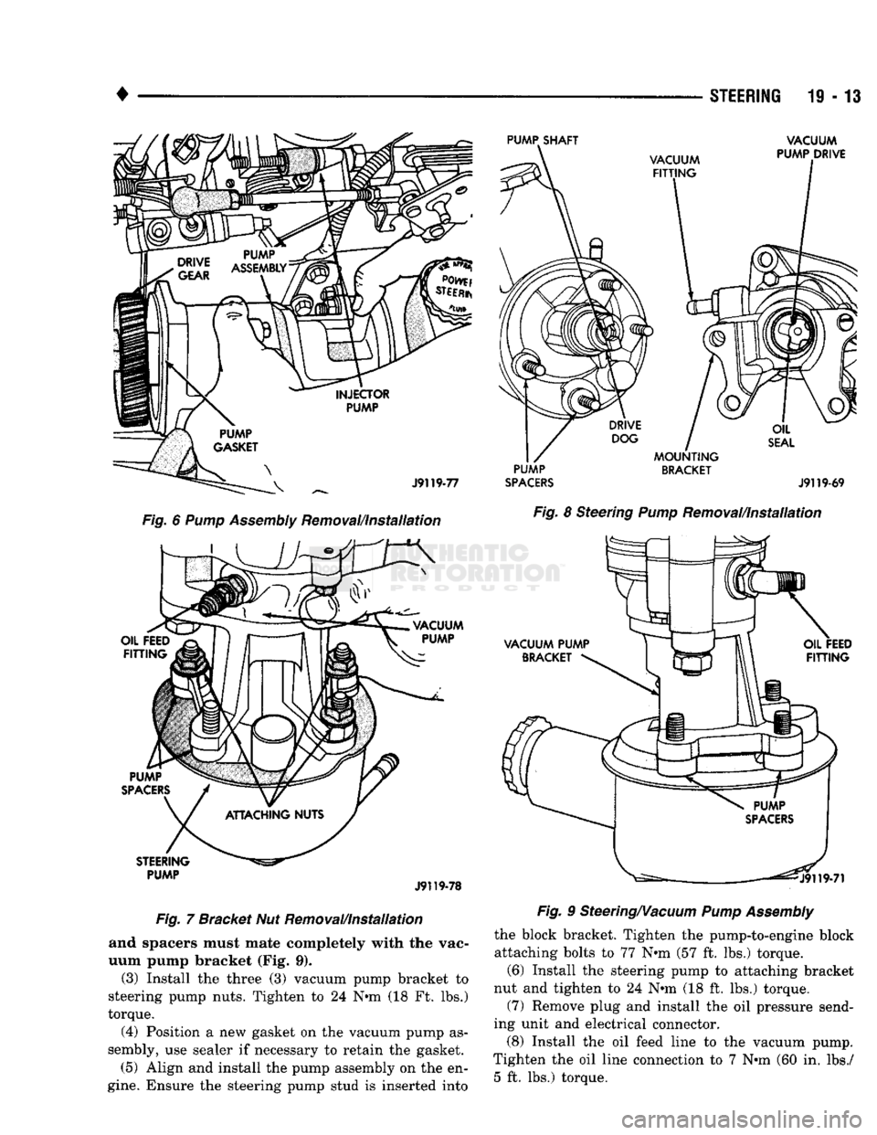
(7) Remove the gasket from the mounting surfaces
on engine block and pump assembly.
(8) Drain the fluid from the steering pump.
(9) Remove the steering pump to vacuum pump
bracket attaching nuts (Fig. 7).
(10) Slide the steering pump from the bracket. Use
care not to damage the internal oil seal in the vac uum pump (Fig. 8).
Fig.
4 Oil
Feed
Line
Removal/Installation
Fig.
5
Pump
Assembly
Upper
Bolt
(11) Remove the two pump body spacers (Fig. 8),
for pump installation.
INSTALLATION (1) Install the two pump body spacers (Fig. 8).
(2) Rotate the drive gear until the steering pump
and vacuum pump drive dogs align. Install the steer
ing pump onto the vacuum pump bracket. Use care
to avoid damaging the oil seal in the vacuum pump during installation. The steering pump housing
Page 974 of 1502
•
STEERING
19 - 13
Fig.
6 Pump Assembly Removal/Installation
PUMP
Jf
119-78
Fig. 7 Bracket Nut Removal/Installation
and spacers must mate completely with the vac
uum pump bracket (Fig. 9).
(3) Install the three (3) vacuum pump bracket to
steering pump nuts. Tighten to 24 N«m (18 Ft. lbs.)
torque.
(4) Position a new gasket on the vacuum pump as
sembly, use sealer if necessary to retain the gasket.
(5) Align and install the pump assembly on the en
gine.
Ensure the steering pump stud is inserted into
PUMP
BRACKET
SPACERS
J9119-69
Fig.
8 Steering
Pump
Removal/Installation
Fig.
9 Steering/Vacuum
Pump Assembly
the block bracket. Tighten the pump-to-engine block
attaching bolts to 77 N*m (57 ft. lbs.) torque.
(6) Install the steering pump to attaching bracket
nut and tighten to 24 N*m (18 ft. lbs.) torque.
(7) Remove plug and install the oil pressure send
ing unit and electrical connector. (8) Install the oil feed line to the vacuum pump.
Tighten the oil line connection to 7 N»m (60 in. lbs./ 5 ft. lbs.) torque.
Page 975 of 1502
19
- 14
STEERING
• (9) Install the fluid hoses to the power steering
pump, Tighten the pressure fitting at the pump to 30
N*m (22 ft. lbs.) torque.
(10) Install and clamp the hose on the vacuum
pump. (11) Fill the reservoir with power steering fluid
only. If necessary, refer to Pump Initial Operation
for detailed instructions.
(12) Start and run the engine. Check the operation
of the brakes, if necessary refer to Group 5, Brakes
for additional information.
PUMP REPLACEMENT—GASOLINE ENGINE
REMOVAL
WARNING:
DO NOT
REMOVE
THE
WATER PUMP COOLANT TUBE UNLESS
THE
COOLANT SYSTEM HAS BEEN DEPRESSUR1ZED
AND
DRAINED*
WARNING:
DO NOT
ATTEMPT
TO
REMOVE
THE
PUMP
WITHOUT
REMOVING
THE
BELT FIRST.
THE
AUTOMATIC TENSIONER
IS
UNDER
A
HIGH
SPRING
LOAD.
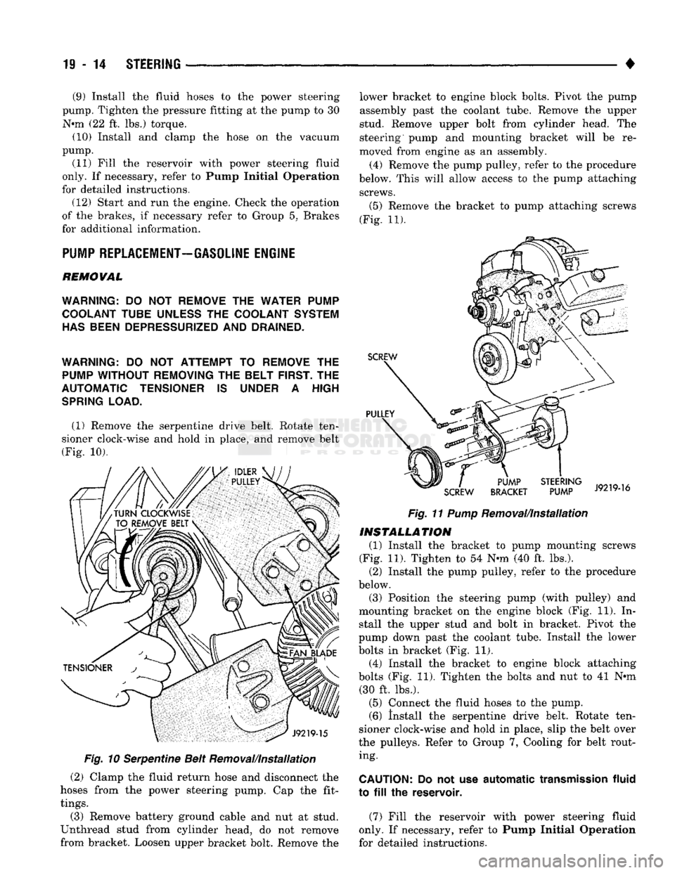
(1) Remove the serpentine drive belt. Rotate ten
sioner clock-wise and hold in place, and remove belt
(Fig. 10).
Fig.
10 Serpentine Belt Removal/Installation
(2) Clamp the fluid return hose and disconnect the
hoses from the power steering pump. Cap the fit
tings.
(3) Remove battery ground cable and nut at stud.
Unthread stud from cylinder head, do not remove
from bracket. Loosen upper bracket bolt. Remove the lower bracket to engine block bolts. Pivot the pump
assembly past the coolant tube. Remove the upper
stud. Remove upper bolt from cylinder head. The
steering pump and mounting bracket will be re
moved from engine as an assembly.
(4) Remove the pump pulley, refer to the procedure
below. This will allow access to the pump attaching screws.
(5)
Remove the bracket to pump attaching screws
(Fig. 11).
Fig.
11
Pump
Removal/Installation
INSTALLATION
(1) Install the bracket to pump mounting screws
(Fig. 11). Tighten to 54 N-m (40 ft. lbs.). (2) Install the pump pulley, refer to the procedure
below.
(3) Position the steering pump (with pulley) and
mounting bracket on the engine block (Fig. 11). In stall the upper stud and bolt in bracket. Pivot the
pump down past the coolant tube. Install the lower
bolts in bracket (Fig. 11). (4) Install the bracket to engine block attaching
bolts (Fig. 11). Tighten the bolts and nut to 41 N*m (30 ft. lbs.).
(5) Connect the fluid hoses to the pump. (6) Install the serpentine drive belt. Rotate ten
sioner clock-wise and hold in place, slip the belt over
the pulleys. Refer to Group 7, Cooling for belt rout ing.
CAUTION:
Do not use
automatic
transmission
fluid
to
fill the
reservoir.
(7) Fill the reservoir with power steering fluid
only. If necessary, refer to Pump Initial Operation
for detailed instructions.
Page 976 of 1502
#
_ ,
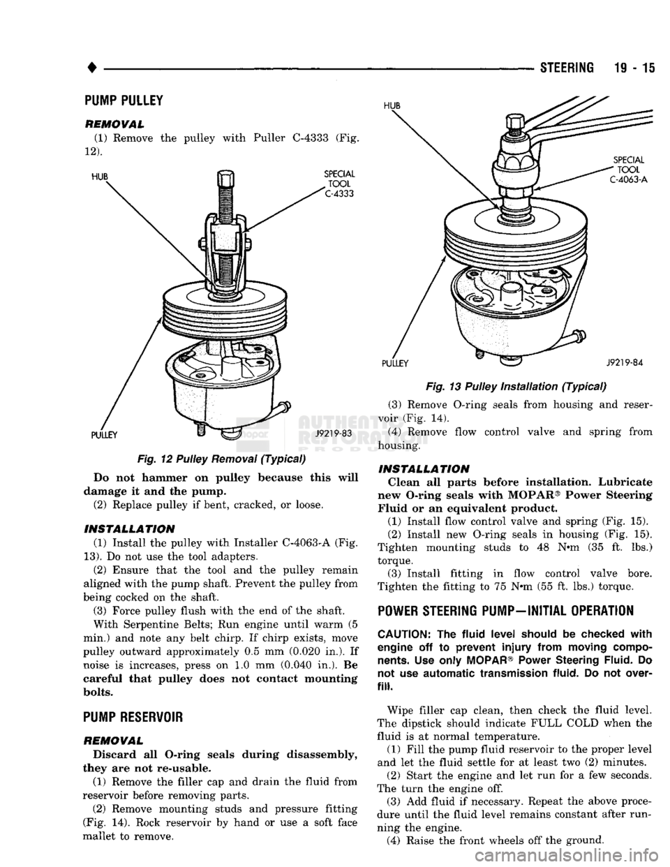
Fig.
12 Pulley
Removal
(Typical)
Do not hammer on pulley because this will
damage it and the pump. (2) Replace pulley if bent, cracked, or loose.
INSTALLATION (1) Install the pulley with Installer C-4063-A (Fig.
13).
Do not use the tool adapters. (2) Ensure that the tool and the pulley remain
aligned with the pump shaft. Prevent the pulley from
being cocked on the shaft.
(3) Force pulley flush with the end of the shaft.
With Serpentine Belts; Run engine until warm (5
min.) and note any belt chirp. If chirp exists, move
pulley outward approximately 0.5 mm (0.020 in.). If noise is increases, press on 1.0 mm (0.040 in.). Be
careful that pulley does not contact mounting
bolts.
PUMP RESERVOIR
REMOVAL
Discard all O-ring seals during disassembly,
they are not re-usable.
(1) Remove the filler cap and drain the fluid from
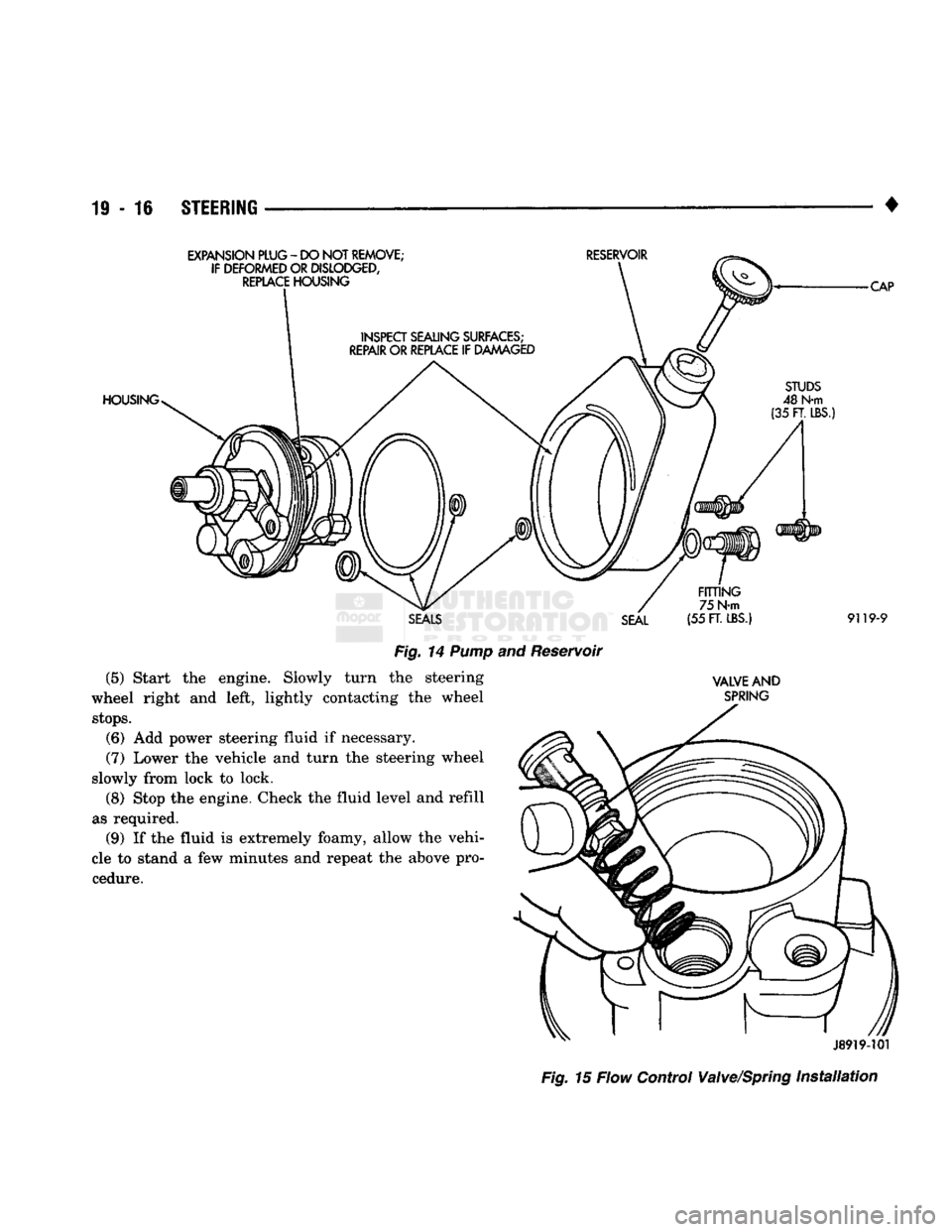
reservoir before removing parts. (2) Remove mounting studs and pressure fitting
(Fig. 14). Rock reservoir by hand or use a soft face
mallet to remove. STEERING 19-15
Fig.
13 Pulley
Installation
(Typical)
(3) Remove O-ring seals from housing and reser
voir (Fig. 14). (4) Remove flow control valve and spring from
housing.
INSTALLATION Clean all parts before installation. Lubricate
new O-ring seals with MOPAR® Power Steering Fluid or an equivalent product.
(1) Install flow control valve and spring (Fig. 15).
(2) Install new O-ring seals in housing (Fig. 15).
Tighten mounting studs to 48 N«m (35 ft. lbs.) torque.
(3) Install fitting in flow control valve bore.
Tighten the fitting to 75 N-m (55 ft. lbs.) torque.
POWER STEERING PUMP-INITIAL OPERATION
CAUTION:
The
fluid
level
should
be
checked
with
engine
off to
prevent
injury
from
moving
compo
nents.
Use
only
MOPAR®
Power
Steering
Fluid.
Do
not
use
automatic
transmission
fluid.
Do not
over
fill.
Wipe filler cap clean, then check the fluid level.
The dipstick should indicate FULL COLD when the fluid is at normal temperature. (1) Fill the pump fluid reservoir to the proper level
and let the fluid settle for at least two (2) minutes. (2) Start the engine and let run for a few seconds.
The turn the engine off. (3) Add fluid if necessary. Repeat the above proce
dure until the fluid level remains constant after run
ning the engine. (4) Raise the front wheels off the ground.
PUMP PULLEY
REMOVAL
(1) Remove the pulley with Puller C-4333 (Fig.
12).
Page 977 of 1502
19
- 16
STEERING
•
EXPANSION PLUG
-
DO NOT
REMOVE; IF DEFORMED
OR
DISLODGED,
REPLACE
HOUSING
RESERVOIR
HOUSING
CAP
SEAL FITTING
75 N-m
(55
FT.
LBS.)
9119-9
(5)
Start the engine. Slowly turn
wheel right and left, lightly contacting the wheel
stops.
(6) Add power steering fluid if necessary.
(7) Lower the vehicle and turn the steering wheel
slowly from lock to lock. (8) Stop the engine. Check the fluid level and refill
as required. (9) If the fluid is extremely foamy, allow the vehi
cle to stand a few minutes and repeat the above pro cedure.
Fig.
14
Pump
and Reservoir
the steering
VALVE
AND
SPRING
J8919-101
Fig.
15 Flow Control Valve/Spring
Installation
Page 978 of 1502
•
STEERING
19 - 17
STEERING
LINKAGE
SERVICE
INFORMATION
The tie-rod end ball stud seals should be inspected
during all oil changes. A damaged ball stud seal requires removal of the
seal. Inspect the tie-rod end ball stud at the throat
opening. Check for lubricant loss, contamination, ball
stud wear or corrosion. If these conditions exist, re
place the tie-rod. A replacement seal can be installed if lubricant is in good condition. Otherwise, a com
plete replacement tie-rod end should be installed. Lu
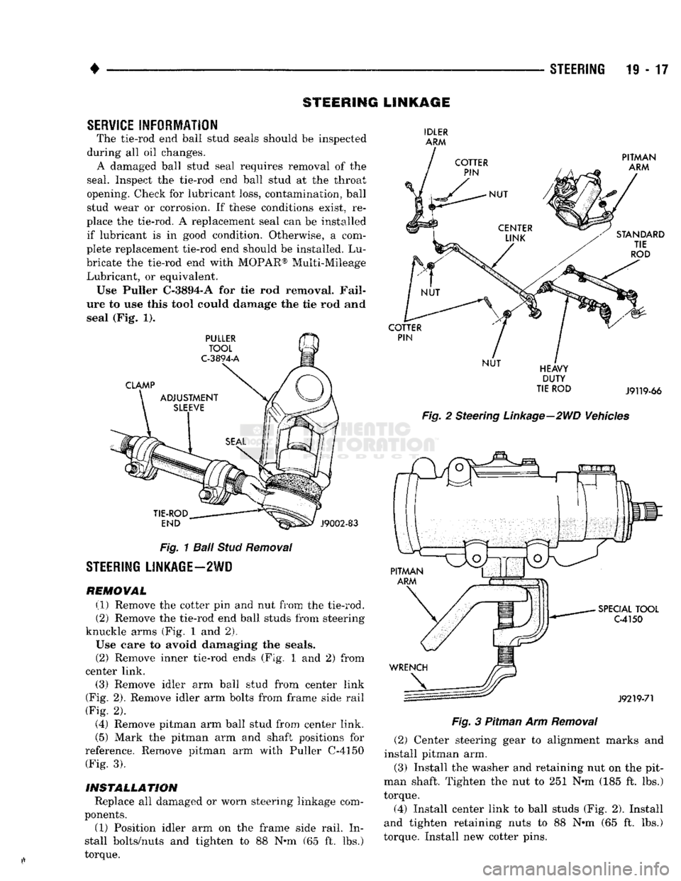
bricate the tie-rod end with MOPAR® Multi-Mileage Lubricant, or equivalent. Use Puller C-3894-A for tie rod removal. Fail
ure to use this tool could damage the tie rod and seal (Fig. 1).
Fig.
1
Ball
Stud
Removal
STEERING
LINKAGE—2WD
REMOWAL (1) Remove the cotter pin and nut from the tie-rod.
(2) Remove the tie-rod end ball studs from steering
knuckle arms (Fig. 1 and 2),
Use care to avoid damaging the seals. (2) Remove inner tie-rod ends (Fig. 1 and 2) from
center link. (3) Remove idler arm ball stud from center link
(Fig. 2). Remove idler arm bolts from frame side rail
(Fig. 2). (4) Remove pitman arm ball stud from center link.
(5) Mark the pitman arm and shaft positions for
reference. Remove pitman arm with Puller C-4150 (Fig. 3).
INSTALLATION
Replace all damaged or worn steering linkage com
ponents.
(1) Position idler arm on the frame side rail. In
stall bolts/nuts and tighten to 88 N-m (65 ft. lbs.)
torque.
IDLER
ARM
DUTY
TIE
ROD
J9119-66
Fig.
2 Steering
Linkage—2WD
Vehicles
Fig.
3 Pitman Arm
Removal
(2) Center steering gear to alignment marks and
install pitman arm.
(3) Install the washer and retaining nut on the pit
man shaft. Tighten the nut to 251 N-m (185 ft. lbs.)
torque. (4) Install center link to ball studs (Fig. 2). Install
and tighten retaining nuts to 88 N-m (65 ft. lbs.)
torque. Install new cotter pins.
Page 979 of 1502
19
- 18
STEERING
•
CAUTION:
It is
possible
to install the
center
link
re
versed
position.
This
will
result
in
incorrect
geome
try and interferences during vehicle jounce. Viewed
from the
front
of the vehicle, the
center
link
ends
should
turn
upward. Viewed
from
the side of the ve
hicle,
the
ends
should
turn
toward
the
front
of the
vehicle. The
tie-rod
ball
studs
enter
the
center
link
bores
from
the
rear.
(5) Install tie-rod ends into center link (Fig. 2).
Tighten the nuts to 54 N»m (40 ft. lbs.) torque. In stall new cotter pins.
(6) Insert tie-rod ends into steering knuckle arm
(Fig. 2). Tighten the nuts to 54 N-m (40 ft. lbs.)
torque. Install new cotter pins. (7) Remove the supports and lower the vehicle to
the surface. Adjust the wheel toe position (refer to
the Alignment Specifications chart within Group 2,
Front Suspension).
Position the clamp on the sleeve so retaining
bolt is located on the bottom side of the sleeve.
(8) After adjustment, tighten the tie-rod adjust
ment sleeve clamp bolt;
• Standard Duty— 25.4 N-m (225 in. lbs.) torque
• Heavy Duty- 34 N-m (25 ft. lbs.) torque
STEERING
LINKAGE—4WD
VEHICLES
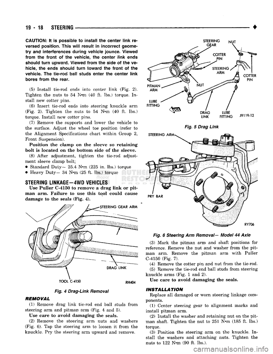
Use Puller C-4150 to remove a drag link or pit
man arm. Failure to use this tool could cause damage to the seals (Fig. 4).
TOOL
C-4150
RH404
Fig.
4
Drag-Link
Removal
REMOVAL (1) Remove drag link tie-rod end ball studs from
steering arm and pitman arm (Fig. 4 and 5).
Use care to avoid damaging the seals. (2) Remove the steering arm nuts and washers
(Fig. 6). Tap the steering arm to loosen it from the
knuckle. Pry the steering arm upward and remove.
STEERING
NUT
LINK
FITTING
J9119-12
Fig.
5
Drag
Link
Fig.
6 Steering Arm
Removal—
Model
44 Axle
(3) Mark the pitman arm and shaft positions for
reference. Remove the nut and washer from the pit
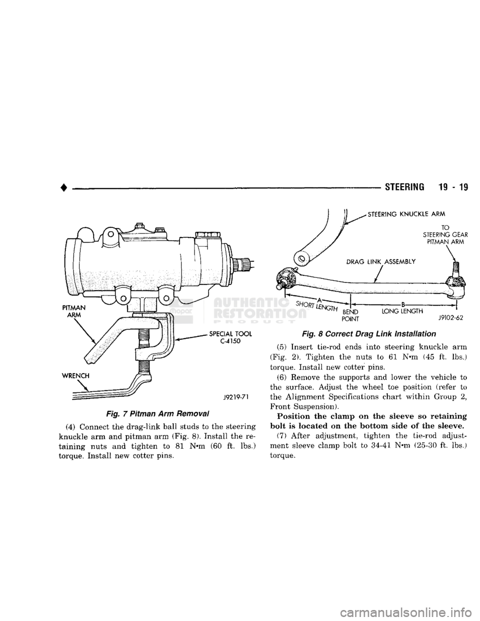
man arm. Remove the pitman arm with Puller C-4150 (Fig. 7). (4) Remove the cotter pin and nut from the tie-rod.
(5) Remove the tie-rod end ball studs from steering
knuckle arms (Fig. 1 and 2).
Use care to avoid damaging the seals.
INSTALLATION
Replace all damaged or worn steering linkage com
ponents. (1) Center steering gear to alignment marks and
install pitman arm.
(2) Install the washer and retaining nut on the pit
man shaft. Tighten the nut to 251 N-m (185 ft. lbs.)
torque. (3) Position the steering arm on the knuckle. In
stall the washers and attaching nuts. Tighten the
nuts to 122 N-m (90 ft. lbs.).
Page 980 of 1502
•
STEERING
19 - 19
Fig.
7 Pitman Arm
Removal
(4) Connect the drag-link ball studs to the steering
knuckle arm and pitman arm (Fig. 8). Install the re
taining nuts and tighten to 81 N»m (60 ft. lbs.)
torque. Install new cotter pins.
POINT
J9102-62
Fig.
8 Correct
Drag
Link
installation
(5) Insert tie-rod ends into steering knuckle arm
(Fig. 2). Tighten the nuts to 61 N-m (45 ft. lbs.)
torque. Install new cotter pins.
(6) Remove the supports and lower the vehicle to
the surface. Adjust the wheel toe position (refer to the Alignment Specifications chart within Group 2, Front Suspension). Position the clamp on the sleeve so retaining
bolt is located on the bottom side of the sleeve. (7) After adjustment, tighten the tie-rod adjust
ment sleeve clamp bolt to 34-41 N-m (25-30 ft. lbs.)
torque.