DODGE TRUCK 1993 Service Repair Manual
Manufacturer: DODGE, Model Year: 1993, Model line: TRUCK, Model: DODGE TRUCK 1993Pages: 1502, PDF Size: 80.97 MB
Page 991 of 1502
11-30 STEERING
Fig.
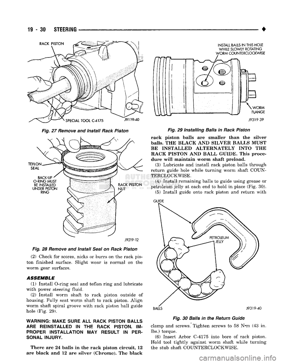
27 Remove and install Rack Piston
J92T9-12
Fig. 28 Remove and Install Seal on Rack Piston (2) Check for scores, nicks or burrs on the rack pis
ton finished surface. Slight wear is normal on the
worm gear surfaces.
ASSEMBLE
(1) Install O-ring seal and teflon ring and lubricate
with power steering fluid. (2) Install worm shaft to rack piston outside of
housing. Fully seat worm shaft to rack piston. Align worm shaft spiral groove with rack piston ball guide
hole (Fig. 29).
WARNING: MAKE SURE ALL RACK PISTON BALLS ARE REINSTALLED IN THE RACK PISTON. IM PROPER INSTALLATION MAY RESULT IN PER
SONAL INJURY.
There are 24 balls in the rack piston circuit, 12
are Mack and 12 are silver (Chrome). The black w
INSTALL BALLS IN THIS HOLE WHILE SLOWLY ROTATING
WORM COUNTERCLOCKWISE
J9319-39
Fig.
29 Installing
Balls
in
Rack
Piston
rack piston balls are smaller than the silver
balls.
THE BLACK AND SILVEE BALLS MUST
BE INSTALLED ALT1ENATELY INTO THE
RACK PISTON AND BALL GUIDE. This proce
dure will maintain worm shaft preload. (3) Lubricate and install rack piston balls through
return guide hole while turning worm shaft COUN
TERCLOCKWISE.
(4) Install remaining balls to guide using grease or
petroleum jelly at each end to hold in place (Fig. 30). (5) Install guide onto rack piston and return with
GUIDE
BALLS J9319-40 Fig.
30
Balls
in the Return
Guide
clamp and screws. Tighten screws to 58 N#m (43 in. lbs.) torque. (6) Insert Arbor C-4175 into bore of rack piston.
Hold tool tightly against worm shaft while turning
the stub shaft COUNTERCLOCKWISE.
Page 992 of 1502
•
STEERING
19 - 31 The rack piston will be forced onto the tool and
hold the rack piston balls in place. (7) Install the races and thrust bearing to worm
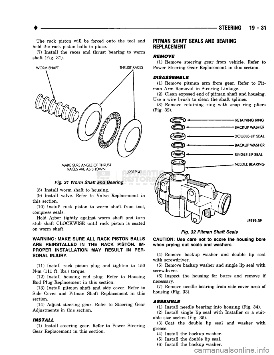
shaft (Fig. 31).
WORM
SHAFT
THRUST
RACES
MAKE
SURE
ANGLE
OF
THRUST
RACES
ARE AS
SHOWN
J9319-41
Fig.
31 Worm Shaft and Bearing
(8) Install worm shaft to housing. (9) Install valve. Refer to Valve Replacement in
this section.
(10) Install rack piston to worm shaft from tool,
compress seals. Hold Arbor tightly against worm shaft and turn
stub shaft CLOCKWISE until rack piston is seated
on worm shaft.
WARNING: MAKE
SURE
ALL
RACK PISTON BALLS
ARE
REINSTALLED
IN THE
RACK PISTON.
IM
PROPER
INSTALLATION
MAY
RESULT
IN
PER
SONAL INJURY.
(11) Install rack piston plug and tighten to 150
N»m (111 ft. lbs.) torque. (12) Install housing end plug. Refer to Housing
End Plug Replacement in this section. (13) Install pitman shaft and side cover. Refer to
Side Cover and Pitman Shaft Replacement in this
section.
(14) Adjust steering gear. Refer to Steering Gear
Adjustments in this section.
PITMAN
SHAFT
SEALS AND
BEARING
REPLACEMENT
REMOVE (1) Remove steering gear from vehicle. Refer to
Power Steering Gear Replacement in this section.
DISASSEMBLE
(1) Remove pitman arm from gear. Refer to Pit
man Arm Removal in Steering Linkage.
(2) Clean exposed end of pitman shaft and housing.
Use a wire brush to clean the shaft splines. (3) Remove retaining ring with snap ring pliers
(Fig. 32).
RETAINING
RING
BACKUP WASHER
DOUBLE-UP SEAL
BACKUP WASHER
SINGLE-LIP SEAL
NEEDLE
BEARING
J8919-39
Fig.
32 Pitman Shaft
Seals
CAUTION:
Use
care
not to
score
the
housing
bore
when
prying
out
seals
and
washers.
(4) Remove backup washer and double lip seal
with screwdriver.
(5) Remove backup washer and single lip seal with
screwdriver. (6) Inspect the housing for burrs and remove if
necessary.
(7) Remove needle bearing from side cover area of
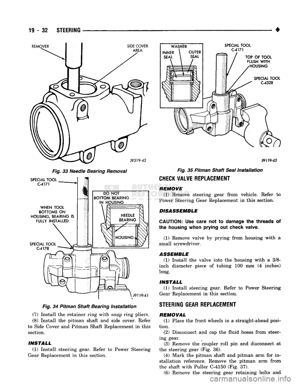
housing (Fig. 33).
ASSEMBLE
(1) Install needle bearing into housing (Fig. 34).
(2) Install single lip seal with Installer or a suit
able size socket (Fig. 35).
(3) Coat the double lip seal and washer with
grease. (4) Install the backup washer. (5) Install the double lip seal.
(6) Install the backup washer.
INSTALL
(1) Install steering gear. Refer to Power Steering
Gear Replacement in this section.
Page 993 of 1502
19
- 32
STEERING
REMOVER SIDE COVER
AREA
SPECIAL
TOOL
C-4171
J9319-42
Fig.
33
Needle Bearing Removal
SPECIAL
TOOL
C-4171
WHEN
TOOL
BOTTOMS
ON
HOUSING,
BEARING
IS
FULLY INSTALLED
SPECIAL
TOOL
C-4178
DO
NOT
BOTTOM BEARING IN HOUSING
\
J9119-4
Fig.
34
Pitman Shaft Bearing
Installation
(7) Install
the
retainer ring with snap ring pliers.
(8) Install
the
pitman shaft
and
side cover. Refer
to Side Cover
and
Pitman Shaft Replacement
in
this section.
TOP
OF
TOOL
FLUSH
WITH
HOUSING
SPECIAL
TOOL
C4328
J9119-42
Fig.
35
Pitman Shaft Seal
Installation
CHECK VALVE REPLACEMENT
REMOVE
(1) Remove steering gear from vehicle. Refer
to
Power Steering Gear Replacement
in
this section.
DISASSEMBLE
CAUTION:
Use
care
not to
damage
the
threads
of
the
housing
when
prying
out
check valve.
(1) Remove valve
by
prying from housing with
a
small screwdriver.
ASSEMBLE (1) Install
the
valve into
the
housing with
a 3/8-
inch diameter piece
of
tubing
100 mm (4
inches) long.
INSTALL (1) Install steering gear. Refer
to
Power Steering
Gear Replacement
in
this section.
STEERING GEAR REPLACEMENT
REMOVAL (1) Place
the
front wheels
in a
straight-ahead posi
tion. (2) Disconnect
and cap the
fluid hoses from steer
ing gear. (3) Remove
the
coupler roll
pin and
disconnect
at
the steering gear
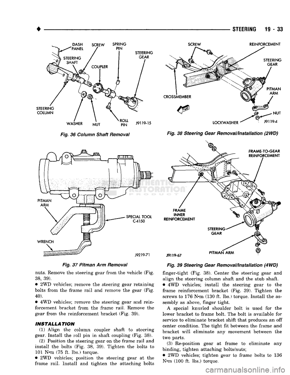
(Fig. 36).
(4) Mark
the
pitman shaft
and
pitman
arm for in
stallation reference. Remove
the
pitman
arm
from
the shaft with Puller C-4150
(Fig. 37).
(6) Remove
the
steering gear retaining bolts
and
INSTALL
(1) Install steering gear. Refer
to
Power Steering
Gear Replacement
in
this section.
Page 994 of 1502
•
STEERING 11-33
Fig.
36
Column
Shaft
Removal
Fig.
37 Pitman Arm
Removal
nuts.
Remove the steering gear from the vehicle (Fig.
38,
39).
9
2WD vehicles; remove the steering gear retaining
bolts from the frame rail and remove the gear (Fig.
40).
• 4WD vehicles; remove the steering gear and rein
forcement bracket from the frame rail. Remove the
gear from the reinforcement bracket (Fig. 39).
INSTALLATION (1) Align the column coupler shaft to steering
gear. Install the roll pin in shaft coupling (Fig. 38).
(2) Position the steering gear on the frame rail and
install the bolts (Fig. 38, 39). Tighten the bolts to 101 N-m (75 ft. lbs.) torque.
• 2WD vehicles; position the steering gear at the
frame rail. Install and tighten the attaching bolts
SCREW
REINFORCEMENT
Fig.
38 Steering Gear Removal/Installation (2WD)
Fig.
39 Steering Gear Removal/Installation (4
WD)
finger-tight (Fig. 38). Center the steering gear and
align the steering column shaft and the stub shaft.
• 4WD vehicles; install the steering gear to the
frame reinforcement bracket (Fig. 39). Tighten the screws to 176 N»m (130 ft. lbs.) torque. Install the assembly as above, finger tight.
A special knurled shoulder bolt is used for the
lower bracket to frame bolt. The bolt is available for service to eliminate bracket shift that produces an off
center condition. The tight fit between the frame and
bracket will eliminate any movement between the two parts.
(3) Re-position gear at frame to eliminate any
binding, tighten attaching bolts/nuts;
• 2WD vehicles; tighten gear to frame bolts to 136 N-m (100 ft. lbs.) torque.
Page 995 of 1502
19
- 34
STEERING
• •
4WD vehicles; tighten gear frame reinforcement
bracket to frame bolts/nuts to 223 N-m (165 ft. lbs.)
torque.
(4) Align and install the pitman arm.
(5) Install the washer and retaining nut on the pit
man shaft. Tighten the nut to 251 N-m (185 ft. lbs.)
torque.
(6) Connect fluid hoses to steering gear, tighten to
28 N-m (21 ft. lbs.). Add fluid, refer to Power Steer
ing Pump Initial Operation.
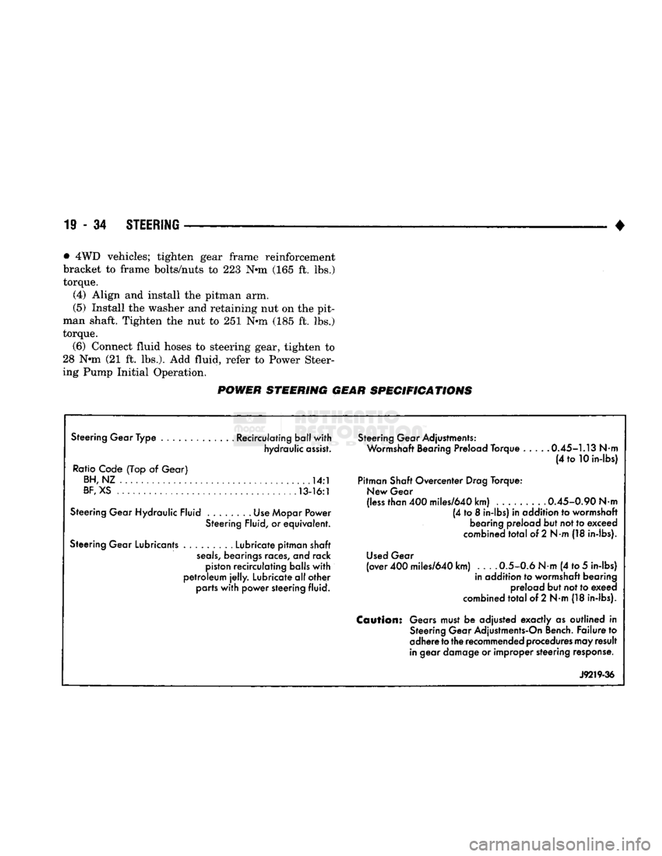
POWER STEERING GEAR SPECIFICATIONS
Steering Gear Type ............. Recirculating ball with hydraulic assist.
Ratio Code (Top
of
Gear) BH,NZ
14:1
BF,
XS 13-16:1
Steering Gear Hydraulic Fluid Use Mopar Power Steering Fluid,
or
equivalent.
Steering Gear Lubricants Lubricate pitman shaft
seals,
bearings races,
and
rack piston recirculating balls with
petroleum
jelly.
Lubricate all other parts with power steering fluid. Steering Gear Adjustments:
Wormshaft Bearing Preload Torque 0.45-1.13
Nm
(4
to
10 in-lbs)
Pitman Shaft Overcenter Drag Torque: New Gear
(less than 400 miles/640 km) ......... 0.45-0.90
Nm
(4
to 8
in-lbs)
in
addition
to
wormshaft bearing preload but not to exceed
combined total
of
2
Nm
(18 in-lbs).
Used Gear
(over 400 miles/640 km) 0.5-0.6
Nm
(4 to
5
in-lbs) in addition
to
wormshaft bearing preload but not to exeed
combined total
of
2 N-m (18 in-lbs).
Caution:
Gears must
be
adjusted exactly
as
outlined
in
Steering Gear Adjustments-On Bench. Failure
to
adhere
to
the recommended procedures may result
in gear damage
or
improper steering response.
J9219-36
Page 996 of 1502
•
STEERING 19 - 3i STEERING COLUMN
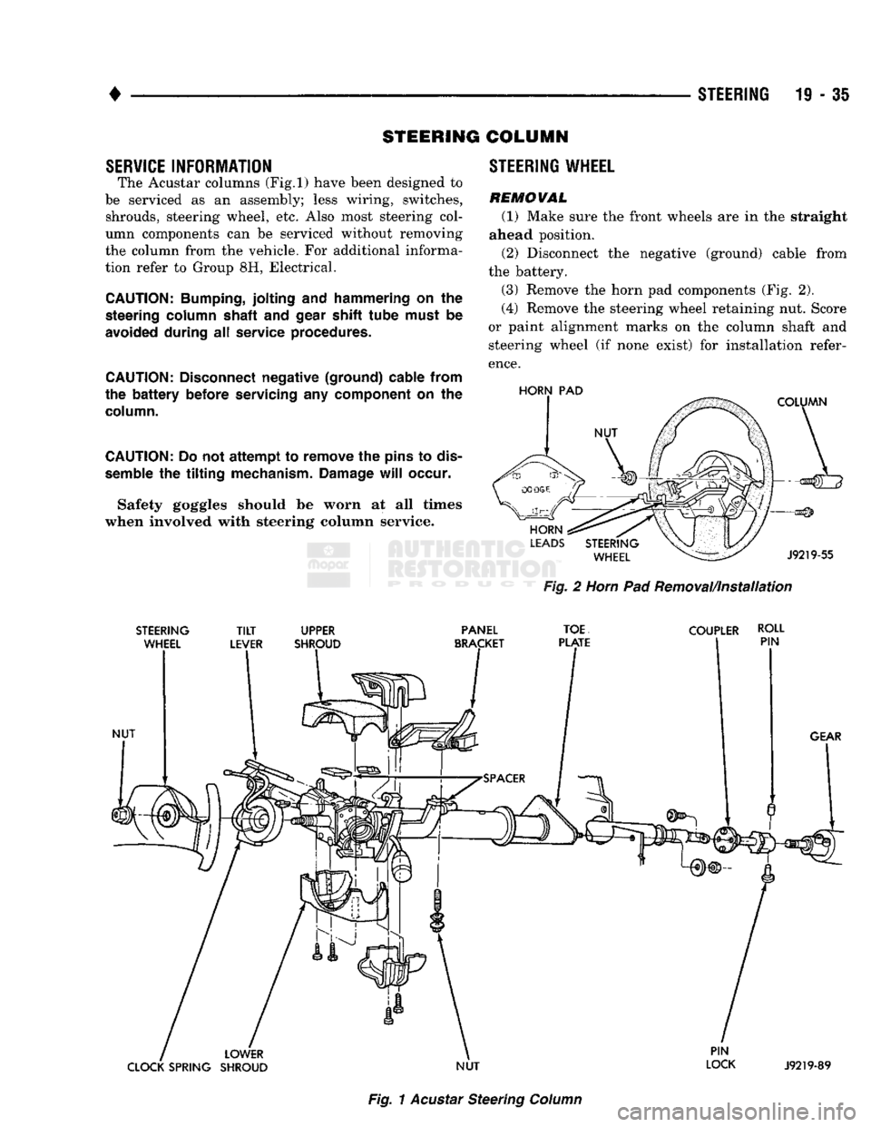
SERVICE INFORMATION The Acustar columns
(Fig.l)
have been designed to
be serviced as an assembly; less wiring, switches, shrouds, steering wheel, etc. Also most steering col
umn components can be serviced without removing
the column from the vehicle. For additional informa
tion refer to Group 8H, Electrical.
CAUTION:
Bumping,
jolting
and
hammering
on the
steering
column
shaft
and
gear shift
tube
must
be
avoided during
all
service procedures.
CAUTION:
Disconnect negative (ground) cable from
the
battery
before servicing
any
component
on the
column.
CAUTION:
Do not
attempt
to remove the
pins
to
dis
semble
the
tilting
mechanism. Damage
will
occur.
Safety goggles should be worn at all times
when involved with steering column service. STEERING WHEEL
REMOWAL
(1) Make sure the front wheels are in the straight
ahead position.
(2) Disconnect the negative (ground) cable from
the battery.
(3) Remove the horn pad components (Fig. 2).
(4) Remove the steering wheel retaining nut. Score
or paint alignment marks on the column shaft and steering wheel (if none exist) for installation refer
ence.
HORN
PAD
Fig.
2
Horn
Pad Removal/installation
STEERING
TILT
UPPER PANEL
TOE
COUPLER ROLL
Fig.
1
Acustar
Steering
Column
Page 997 of 1502
19-36 STEERING
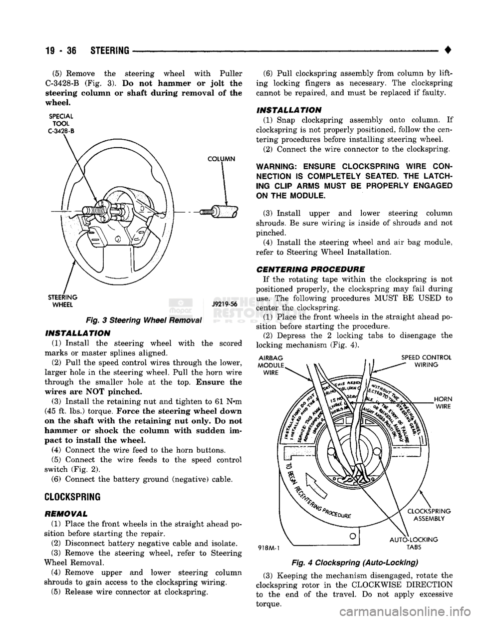
• (5) Remove the steering wheel with Puller
C-3428-B (Fig. 3). Do not hammer or jolt the
steering column or shaft during removal of the
wheel.
SPECIAL TOOL
C-3428-B
STEERING WHEEL J9219-56
Fig.
3 Steering
Wheel
Removal
INSTALLATION
(1) Install the steering wheel with the scored
marks or master splines aligned. (2) Pull the speed control wires through the lower,
larger hole in the steering wheel. Pull the horn wire
through the smaller hole at the top. Ensure the
wires are NOT pinched.
(3) Install the retaining nut and tighten to 61 N«m
(45 ft. lbs.) torque. Force the steering wheel down
on the shaft with the retaining nut only. Do not
hammer or shock the column with sudden im
pact to install the wheel.
(4) Connect the wire feed to the horn buttons.
(5) Connect the wire feeds to the speed control
switch (Fig. 2).
(6) Connect the battery ground (negative) cable.
CLOCKSPRING
REMOVAL
(1) Place the front wheels in the straight ahead po
sition before starting the repair.
(2) Disconnect battery negative cable and isolate.
(3) Remove the steering wheel, refer to Steering
Wheel Removal. (4) Remove upper and lower steering column
shrouds to gain access to the clockspring wiring.
(5) Release wire connector at clockspring. (6) Pull clockspring assembly from column by lift
ing locking fingers as necessary. The clockspring
cannot be repaired, and must be replaced if faulty.
INSTALLATION
(1) Snap clockspring assembly onto column. If
clockspring is not properly positioned, follow the cen
tering procedures before installing steering wheel.
(2) Connect the wire connector to the clockspring.
WARNING: ENSURE CLOCKSPRING WIRE CON NECTION
IS
COMPLETELY SEATED.
THE
LATCH
ING CLIP ARMS MUST
BE
PROPERLY ENGAGED
ON
THE
MODULE.
(3) Install upper and lower steering column
shrouds. Be sure wiring is inside of shrouds and not
pinched. (4) Install the steering wheel and air bag module,
refer to Steering Wheel Installation.
CENTERING
PROCEDURE
If the rotating tape within the clockspring is not
positioned properly, the clockspring may fail during
use.
The following procedures MUST BE USED to
center the clockspring.
(1) Place the front wheels in the straight ahead po
sition before starting the procedure. (2) Depress the 2 locking tabs to disengage the
locking mechanism (Fig. 4).
Fig.
4
Clockspring
(Auto-Locking)
(3) Keeping the mechanism disengaged, rotate the
clockspring rotor in the CLOCKWISE DIRECTION
to the end of the travel. Do not apply excessive
torque.
Page 998 of 1502
•
STEERING
19 • 37 (4) From the end of travel, rotate the rotor 2 1/2
full turns in the COUNTER CLOCKWISE direction.
The horn wire should end up at the top and the squib
wire at the bottom (Fig. 4).
(5) Install the steering wheel, refer to Steering
Wheel Installation.
COLUMN—
REMOVAL/INSTALLATION
CAUTION:
Bumping,
jolting
and
hammering
on the
steering
column
shaft
and
gear
shift
tube
must
be
avoided
during
all
service
procedures.
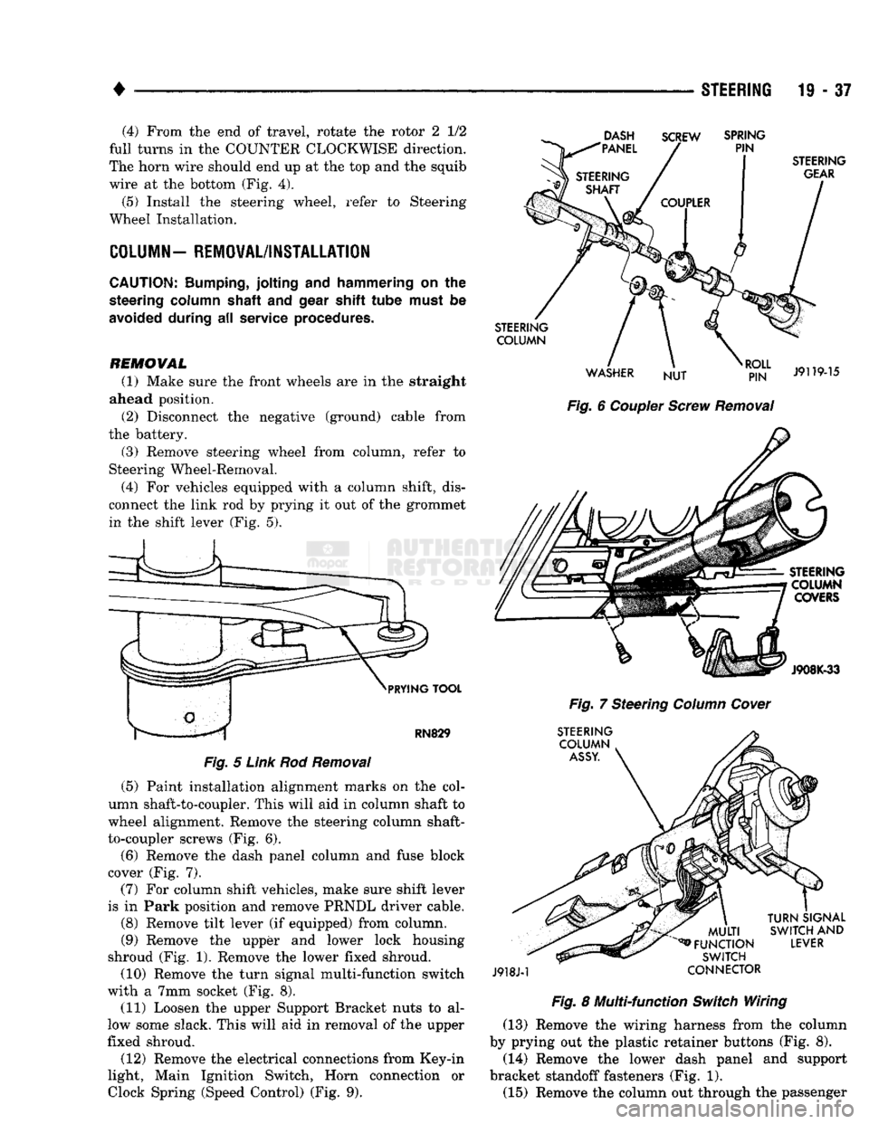
REMOVAL (1) Make sure the front wheels are in the straight
ahead position.
(2) Disconnect the negative (ground) cable from
the battery.
(3) Remove steering wheel from column, refer to
Steering Wheel-Removal.
(4) For vehicles equipped with a column shift, dis
connect the link rod by prying it out of the grommet in the shift lever (Fig. 5).
DASH
"PANEL SCREW
SPRING
PIN
PRYING
TOOL
RN829
Fig.
5
Link
Rod
Removal
(5) Paint installation alignment marks on the col
umn shaft-to-coupler. This will aid in column shaft to
wheel alignment. Remove the steering column shaft-
to-coupler screws (Fig. 6).
(6) Remove the dash panel column and fuse block
cover (Fig. 7).
(7) For column shift vehicles, make sure shift lever
is in Park position and remove PRNDL driver cable.
(8) Remove tilt lever (if equipped) from column.
(9) Remove the upper and lower lock housing
shroud (Fig. 1). Remove the lower fixed shroud.
(10) Remove the turn signal multi-function switch
with a 7mm socket (Fig. 8). (11) Loosen the upper Support Bracket nuts to al
low some slack. This will aid in removal of the upper
fixed shroud.
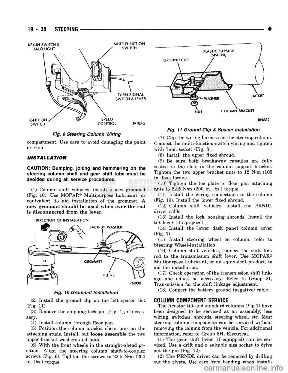
(12) Remove the electrical connections from Key-in
light, Main Ignition Switch, Horn connection or
Clock
Spring (Speed
Control)
(Fig. 9).
STEERING
GEAR
STEERING COLUMN
WASHER NUT
RJ?N"
J9119-15
Fig.
6
Coupler
Screw
Removal
STEERING COLUMN COVERS
J908K-33
Fig.
7 Steering
Column
Cover
STEERING COLUMN
ASSY.
J918J-1
MULTI
^FUNCTION
SWITCH
CONNECTOR
TURN
SIGNAL
SWITCH
AND
LEVER
Fig.
8 Multi-function
Switch
Wiring (13) Remove the wiring harness from the column
by prying out the plastic retainer buttons (Fig. 8).
(14) Remove the lower dash panel and support
bracket standoff fasteners (Fig. 1). (15) Remove the column out through the passenger
Page 999 of 1502
19
- 38
STEERING
KEY-IN SWITCH
&
MULTI FUNCTION
SWITCH CONTROL J918J-2
Fig.
9 Steering
Column
Wiring compartment. Use care to avoid damaging the paint
or trim.
INSTALLATION
CAUTION:
Bumping,
jolting and hammering on the
steering
column
shaft
and
gear
shift tube
must
be
avoided
during all service
procedures.
(1) Column shift vehicles, install a new grommet
(Fig. 10). Use MOPAR® Multipurpose Lubricant, or
equivalent, to aid installation of the grommet. A
new grommet should be used when ever the rod
is disconnected from the lever.
DIRECTION
OF
INSTALLATION
RN830
Fig.
10
Grommet
Installation
(2) Install the ground clip on the left spacer slot
(Fig. 11). (3) Remove the shipping lock pin (Fig. 1), if neces
sary. (4) Install column through floor pan.
(5) Position the column bracket shear pins on the
attaching studs. Install, but loose assemble the two
upper bracket washers and nuts. (6) With the front wheels in the straight-ahead po
sition. Align the steering column shaft-to-coupler
screws (Fig. 6). Tighten the screws to 22.5 N*m (200
in. lbs.) torque. RN832
Fig.
11
Ground
Clip &
Spacer
Installation
(7) Clip the wiring harness on the steering column.
Connect the multi-function switch wiring and tighten
with 7mm socket (Fig. 8).
(8) Install the upper fixed shroud.
(9) Be sure both breakaway capsules are fully
seated in the slots in the column support bracket.
Tighten the two upper bracket nuts to 12 N-m (105
in. lbs.) torque.
(10) Tighten the toe plate to floor pan attaching
nuts to 22.5 N-m (200 in. lbs.) torque.
(11) Install the wiring connections to the column
(Fig. 10). Install the lower fixed shroud. (12) Column shift vehicles, install the PRNDL
driver cable. (13) Install the lock housing shrouds. Install the
tilt lever (if equipped). (14) Install the lower dash panel column cover
(Fig. 7).
(15) Install steering wheel on column, refer to
Steering Wheel-Installation.
(16) Column shift vehicles, connect the shift link
rod to the transmission shift lever. Use MOPAR®
Multipurpose Lubricant, or an equivalent product, to
aid the installation. (17) Check operation of the transmission shift link
age and adjust as necessary. Refer to Group 21,
Transmission for the shift linkage adjustment.
(18) Connect the battery ground (negative) cable.
COLUMN
COMPONENT
SERVICE
The Acustar tilt and standard columns (Fig.l) have
been designed to be serviced as an assembly; less
wiring, switches, shrouds, steering wheel, etc. Most steering column components can be serviced without
removing the column from the vehicle. For additional
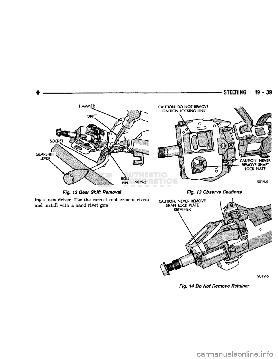
information, refer to Group 8H, Electrical. (1) The gear shift lever (if equipped) can be ser
viced. Use a drift and a suitable size socket to drive out the pin (Fig. 12). (2) The PRNDL driver can be removed by drilling
out the rivets. Use care from bending when install-
Page 1000 of 1502
•
STEERING
19-39
Fig. 14 Do Not
Remove
Retainer