DODGE TRUCK 1993 Service Repair Manual
Manufacturer: DODGE, Model Year: 1993, Model line: TRUCK, Model: DODGE TRUCK 1993Pages: 1502, PDF Size: 80.97 MB
Page 961 of 1502

Page 962 of 1502
•
STEERING STEERING
19-1
CONTENTS
page
GENERAL INFORMATION
1
POWER STEERING PUMP
11
POWER STEERING SYSTEM DIAGNOSIS
..... 2
RECIRCULATING
BALL
POWER STEERING GEAR
. 20
page
STEERING COLUMN
3i
STEERING LINKAGE
17
TORQUE SPECIFICATIONS
40
GENERAL
INFORMATION
STEERING SYSTEM COMPONENTS
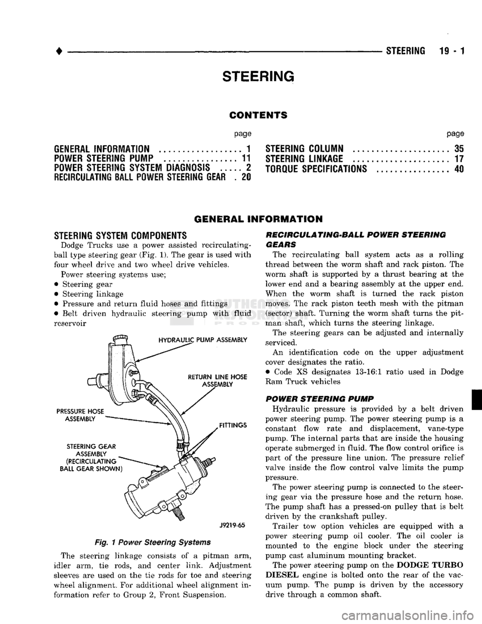
Dodge Trucks
use a
power
assisted recirculating-
ball
type steering gear
(Fig.
1). The
gear
is
used with
four
wheel drive
and two
wheel
drive
vehicles. Power steering systems
use;
•
Steering
gear • Steering linkage
• Pressure
and
return fluid hoses
and
fittings
• Belt driven hydraulic steering pump with
fluid
reservoir
J9219-65
Fig.
1
Power
Steering
Systems
The steering linkage consists
of a
pitman
arm,
idler
arm, tie
rods,
and
center link. Adjustment
sleeves
are
used
on the tie
rods
for toe and
steering
wheel alignment.
For
additional wheel alignment
in
formation refer
to
Group
2,
Front Suspension. RECIRCULA TING-BALL
POWER
STEERING
GEARS
The recirculating ball system acts
as a
rolling
thread between
the
worm shaft
and
rack piston.
The
worm shaft
is
supported
by a
thrust bearing
at the
lower
end
and a
bearing assembly
at
the
upper
end.
When
the
worm shaft
is
turned
the
rack piston
moves.
The
rack piston teeth mesh with
the
pitman (sector) shaft. Turning
the
worm shaft turns
the
pit
man shaft, which turns
the
steering linkage.
The steering gears
can be
adjusted
and
internally
serviced.
An identification code
on the
upper adjustment
cover designates
the
ratio.
• Code
XS
designates 13-16:1 ratio used
in
Dodge
Ram Truck vehicles
POWER
STEERING
PUMP
Hydraulic pressure
is
provided
by a
belt driven
power steering pump.
The
power steering pump
is a
constant flow rate
and
displacement, vane-type
pump.
The
internal parts that
are
inside
the
housing operate submerged
in
fluid.
The
flow control orifice
is
part
of
the
pressure line union.
The
pressure relief
valve inside
the
flow control valve limits
the
pump
pressure.
The power steering pump
is
connected
to
the
steer
ing gear
via the
pressure hose
and the
return hose.
The pump shaft
has
a
pressed-on pulley that
is
belt driven
by the
crankshaft pulley.
Trailer
tow
option vehicles
are
equipped with
a
power steering pump
oil
cooler.
The oil
cooler
is
mounted
to the
engine block under
the
steering
pump cast aluminum mounting bracket.
The power steering pump
on
the
DODGE TURBO
DIESEL engine
is
bolted onto
the
rear
of
the
vac
uum pump.
The
pump
is
driven
by the
accessory drive through
a
common shaft.
Page 963 of 1502
19
- 2
STEERING
• Dodge
Ram
Truck power steering pumps
are
not interchangeable with
pumps installed
in
other vehicles.
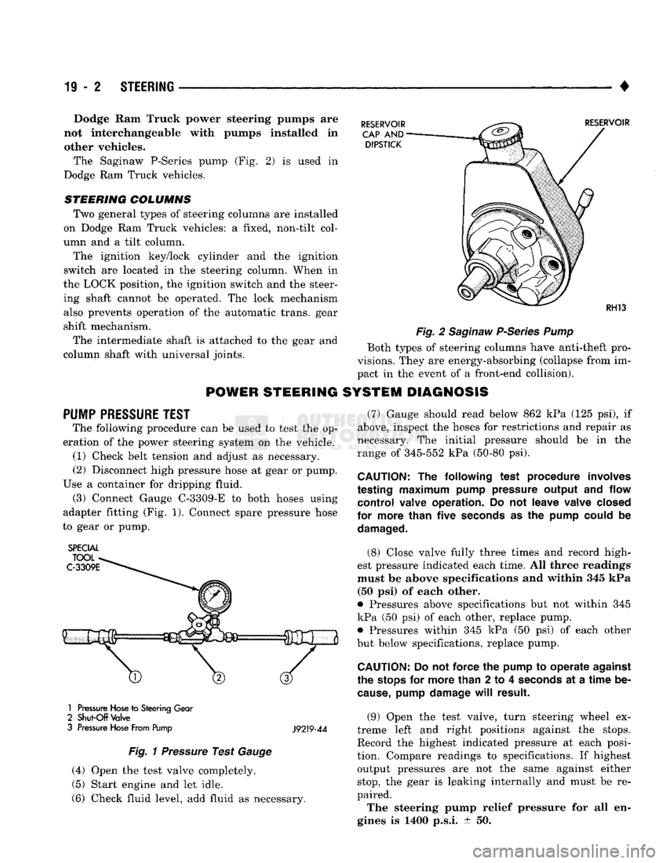
The Saginaw P-Series pump
(Fig. 2) is
used
in
Dodge
Ram
Truck vehicles.
STEERING COLUMNS
Two general types
of
steering columns
are
installed
on Dodge
Ram
Truck vehicles:
a
fixed, non-tilt col
umn
and a
tilt column.
The ignition key/lock cylinder
and the
ignition
switch
are
located
in the
steering column. When
in
the LOCK position,
the
ignition switch
and the
steer ing shaft cannot
be
operated.
The
lock mechanism also prevents operation
of the
automatic trans, gear
shift mechanism.
The intermediate shaft
is
attached
to the
gear
and
column shaft with universal joints.
POWER
STEERING
PUMP
PRESSURE
TEST
The following procedure
can be
used
to
test
the op
eration
of the
power steering system
on the
vehicle. (1) Check belt tension
and
adjust
as
necessary.
(2) Disconnect high pressure hose
at
gear
or
pump.
Use
a
container
for
dripping fluid. (3) Connect Gauge C-3309-E
to
both hoses using
adapter fitting
(Fig. 1).
Connect spare pressure hose
to gear
or
pump.
SPECIAL
1
Pressure
Hose
to
Steering
Gear
2
Shut-Off
Valve
3
Pressure
Hose
From Pump
J9219-44
Fig.
1
Pressure
Test
Gauge
(4) Open
the
test valve completely.
(5) Start engine
and let
idle.
(6) Check fluid level,
add
fluid
as
necessary.
Fig.
2
Saginaw
P-Series
Pump
Both types
of
steering columns have anti-theft pro
visions. They
are
energy-absorbing (collapse from
im
pact
in the
event
of a
front-end collision).
SYSTEM DIAGNOSIS
(7) Gauge should read below
862 kPa (125 psi), if
above, inspect
the
hoses
for
restrictions
and
repair
as
necessary.
The
initial pressure should
be in the
range
of
345-552
kPa
(50-80
psi).
CAUTION:
The
following test procedure involves
testing
maximum
pump pressure output
and
flow control valve operation.
Do not
leave valve closed
for more than five
seconds
as the
pump could
be
damaged.
(8) Close valve fully three times
and
record high
est pressure indicated each time.
All
three readings
must
be
above specifications
and
within
345 kPa
(50
psi) of
each other.
9
Pressures above specifications
but not
within
345
kPa
(50 psi) of
each other, replace pump. • Pressures within
345 kPa (50 psi) of
each other
but below specifications, replace pump.
CAUTION:
Do not
force
the
pump
to
operate against
the
stops
for
more than
2 to 4
seconds
at a
time
be
cause,
pump damage
will
result.
(9) Open
the
test valve, turn steering wheel
ex
treme left
and
right positions against
the
stops.
Record
the
highest indicated pressure
at
each posi
tion. Compare readings
to
specifications.
If
highest output pressures
are not the
same against either
stop,
the
gear
is
leaking internally
and
must
be re
paired.
The steering pump relief pressure
for all en
gines
is 1400
p.s.i.
± 50.
Page 964 of 1502
•
STEERING
19 - 3
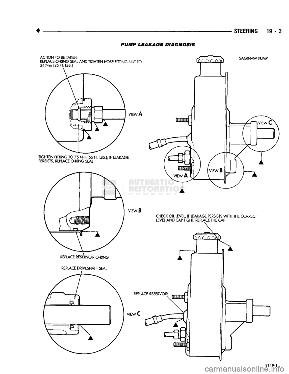
PUMP
LEAKAGE DIAGNOSIS
9119-1
Page 965 of 1502
19
- 4
STEERING
POWER STEERING SYSTEM DIAGNOSIS
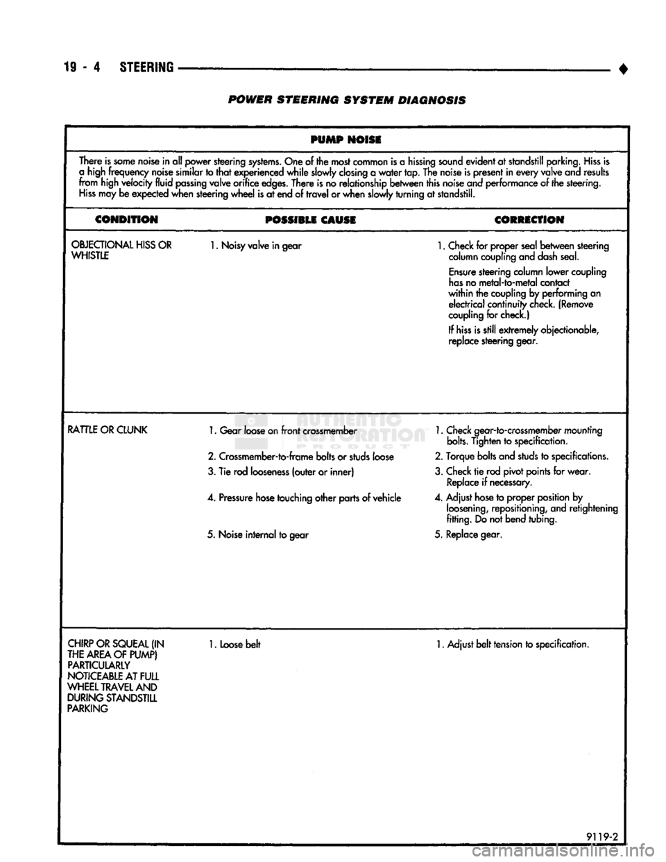
PUMP
NOISI
There is some noise in all power steering systems. One of the most common is a hissing sound evident at standstill parking. Hiss is
a high frequency noise similar to that experienced while slowly closing a water tap. The noise is present in every valve and results
from high velocity
fluid
passing valve orifice edges. There is no relationship between this noise and performance of the steering. Hiss may be expected when steering wheel is at end of travel or when slowly turning at standstill.
CONDITION
POSSIBU CAUSI
CORRICriON
OBJECTIONALHISSOR
WHISTLE 1.
Noisy valve in gear
1.
Check for proper seal between steering
column coupling and dash seal.
Ensure steering column lower coupling
has no metal-to-metal contact
within the coupling by performing an electrical continuity check. (Remove
coupling for check.)
If hiss is still extremely objectionable,
replace steering gear.
RATTLE
OR CLUNK
1.
Gear loose on front crossmember
2.
Crossmember-to-frame bolts or studs loose
3.
Tie rod looseness (outer or inner)
4.
Pressure hose touching other parts of vehicle
5.
Noise internal to gear
1.
Check gear-to-crossmember mounting
bolts.
Tighten to specification.
2.
Torque bolts and studs to specifications.
3.
Check tie rod pivot points for wear. Replace if necessary.
4.
Adjust hose to proper position by loosening, repositioning, and retightening
fitting. Do not bend tubing.
5.
Replace gear.
CHIRP OR SQUEAL (IN
THE AREA OF PUMP) PARTICULARLY
NOTICEABLE AT
FULL
WHEEL TRAVEL AND DURING STANDSTILL
PARKING
1.
Loose belt
1.
Adjust belt tension to specification.
9119-2
Page 966 of 1502
•
STEERING
19-5 POWER STEERING SYSTEM DIAGNOSIS
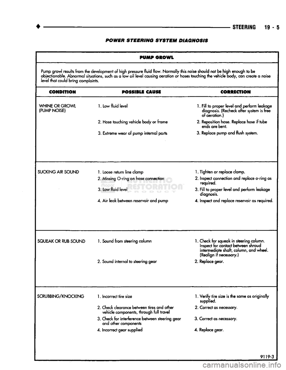
PUMP GROWL
Pump growl results from the development of high pressure fluid flow. Normally this noise should not be high enough to be
objectionable. Abnormal situations, such as a low oil level causing aeration or hoses touching the vehicle body, can create a noise level that could bring complaints.
CONDITION
POSSIBLE
CAUSE
CORRECTION
WHINE OR GROWL (PUMP NOISE)
1. Low
fluid level
2.
Hose touching vehicle body or frame
3.
Extreme wear of pump internal parts
1.
Fill to proper level and perform leakage
diagnosis. (Recheck after system is free
of aeration.)
2.
Reposition hose. Replace hose if tube ends are bent.
3.
Replace pump and
flush
system.
SUCKING
AIR
SOUND
1.
Loose return line clamp
2.
Missing
O-ring
on hose connection
3. Low
fluid level
4.
Air leak between reservoir and pump
1.
Tighten or replace clamp.
2.
Inspect connection and replace
o-ring
as required.
3.
Fill to proper level and perform leakage diagnosis.
4.
Inspect and replace reservoir as required.
SQUEAK
OR
RUB
SOUND
1.
Sound from steering column
2.
Sound internal to steering gear
1.
Check for squeak in steering column.
Inspect for contact between shroud
intermediate shaft, column, and wheel.
(Realign if necessary.)
2.
Replace gear.
SCRUBBING/KNOCKING
1.
Incorrect tire size
2.
Check clearance between tires and other vehicle components, through full travel
3.
Check for interference between steering gear and other components
4.
Incorrect gear supplied
1.
Verify tire size is the same as originally
supplied.
2.
Correct as necessary.
3.
Correct as necessary.
4.
Replace gear.
9119-3
Page 967 of 1502
19
- 6
STEERING
• POWER STEERING SYSTEM DIAGNOSIS
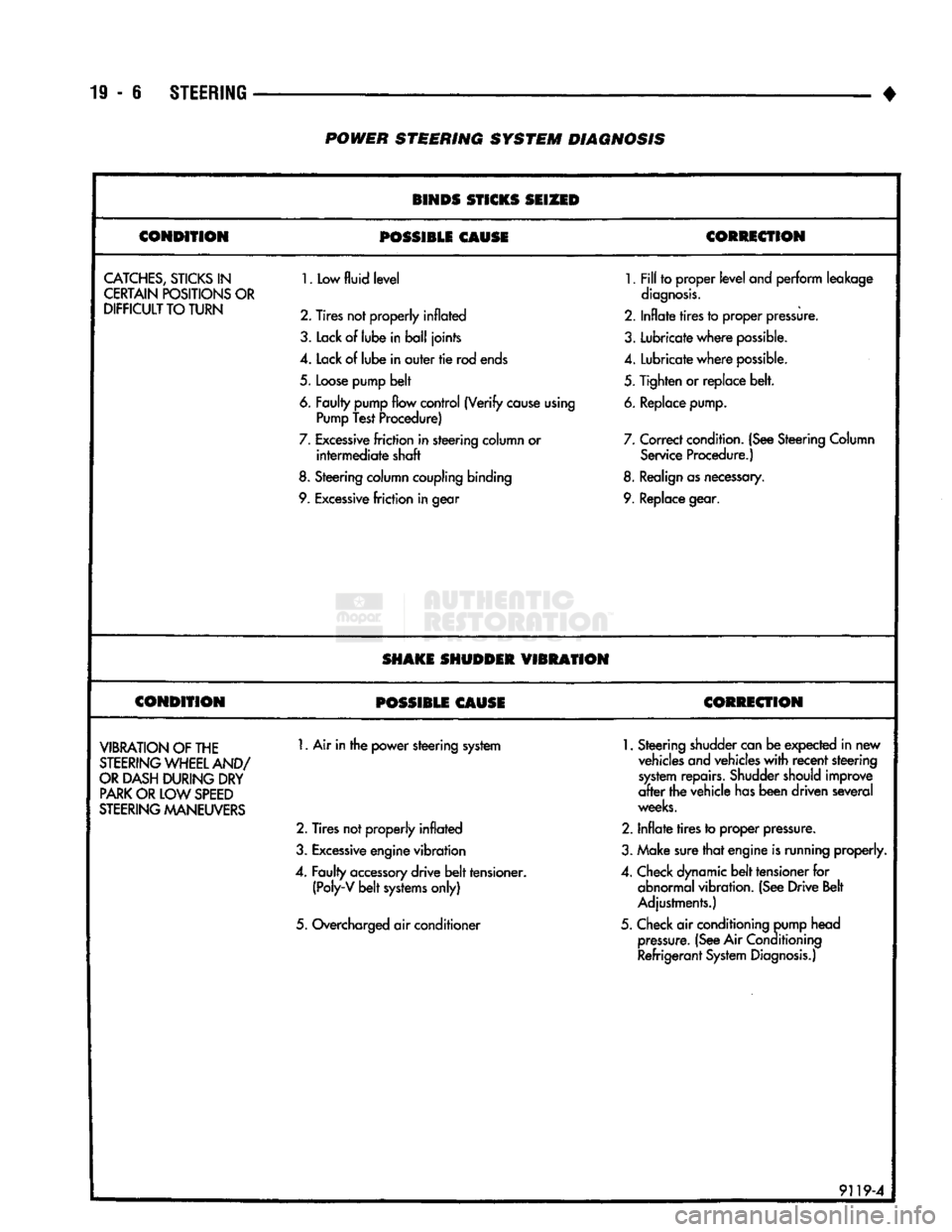
BINDS STICKS SEIZED
CONDITION
POSSIBLE
CAUSE CORRECTION
CATCHES,
STICKS
IN
CERTAIN POSITIONS OR
DIFFICULT
TO TURN
1.
Low
fluid level
2. Tires not properly
inflated
3.
Lack
of
lube
in ball joints
4.
Lack of lube in outer tie rod ends
5.
Loose pump belt
6. Faulty pump flow control (Verify cause using Pump Test Procedure)
7.
Excessive friction in steering column or intermediate shaft
8.
Steering column coupling binding
9. Excessive friction in gear
1.
Fill to proper level
and
perform leakage
diagnosis.
2.
Inflate tires to proper pressure.
3.
Lubricate where possible.
4.
Lubricate where possible.
5.
Tighten or replace belt.
6. Replace pump.
7.
Correct condition. (See Steering Column Service Procedure.)
8. Realign as necessary.
9. Replace gear.
SHAKE SHUDDER
VIBRATION
CONDITION
POSSIBLE CAUSE CORRECTION
VIBRATION
OF THE
STEERING
WHEEL AND/
OR
DASH DURING DRY
PARK
OR LOW
SPEED
STEERING
MANEUVERS
1.
Air in the power steering system
2.
Tires not properly inflated
3.
Excessive engine vibration
4.
Faulty accessory drive belt tensioner. (Poly-V belt systems only)
5.
Overcharged air conditioner
1.
Steering shudder can be expected in new
vehicles and vehicles with recent steering system repairs. Shudder should improve
after the vehicle has been driven several
weeks.
2.
Inflate tires to proper pressure.
3.
Make sure that engine is running properly.
4.
Check dynamic belt tensioner for abnormal vibration. (See Drive Belt
Adjustments.)
5.
Check air conditioning pump head pressure. (See Air
Conditioning
Refrigerant System Diagnosis.)
9119-4
Page 968 of 1502
•
STEERING
19 - 7 POWER STEERING SYSTEM DIAGNOSIS
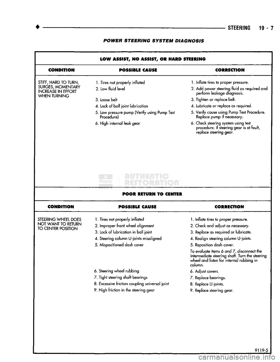
LOW
ASSIST,
NO
ASSIST,
OR
HARD
STEERING
CONDITION
POSSIBLE CAUSE
CORRECTION
STIFF,
HARD
TO TURN,
SURGES,
MOMENTARY
INCREASE
IN
EFFORT
WHEN
TURNING
1.
Tires not properly inflated
2. Low
fluid level
3.
Loose belt
1.
Inflate tires to proper pressure.
2.
Add power steering fluid as required and perform leakage diagnosis.
3.
Tighten or replace belt.
4.
Lack of ball joint lubrication
4.
Lubricate or replace as required.
5.
Low pressure pump (Verify using Pump Test Procedure)
5.
Verify cause using Pump Test Procedure.
Replace pump if necessary.
6. High internal leak gear 6. Check steering system using test
procedure. If steering gear is at fault, replace steering gear.
POOR RETURN
TO
CENTER
CONDITION POSSIBLE CAUSE CORRECTION
STEERING
WHEEL
DOES
NOT WANT
TO
RETURN
TO CENTER POSITION
1.
Tires not properly inflated
2.
Improper front wheel alignment
3.
Lack of lubrication in ball joint
1.
Inflate tires to proper pressure.
2.
Check and adjust as necessary.
3.
Replace as required or lubricate.
4.
Steering column U-joints misaligned
4.
Realign steering column U-joints.
5.
Mispositioned dash cover
5.
Reposition dash cover.
To
evaluate items 6 and 7, disconnect the intermediate steering shaft. Turn the steering
wheel and listen for internal rubbing in column.
6. Steering wheel rubbing 6. Adjust covers.
7.
Tight steering shaft bearings
7.
Replace bearings.
8. Excessive friction coupling universal joint 8. Replace U-joints.
9. High friction in the steering gear 9. Replace steering gear.
91195
Page 969 of 1502
19
- 8
STEERING
POWER
STEERING
SYSTEM
DIAGNOSIS
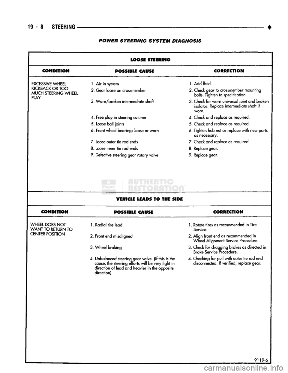
LOOSE
STEERING
CONDITION
POSSIBLE
CAUSE
CORRECTION
EXCESSIVE
WHEEL
KICKBACK
OR
TOO
MUCH
STEERING
WHEEL
PLAY
1.
Air in system
2.
Gear
loose
on
crossmember
3.
Worn/broken intermediate shaft
4.
Free
play in steering column
5.
Loose
ball
joints
6. Front wheel bearings
loose
or worn
7.
Loose
outer tie rod
ends
8.
Loose
inner
tie
rod
ends
9.
Defective steering gear
rotary
valve
1.
Add
fluid.
2.
Check
gear
to
crossmember
mounting bolts. Tighten
to
specification,
3.
Check
for worn universal
joint
ond
broken isolator.
Replace
intermediate shaft
if
worn.
4.
Check
and replace
as
required. 5.
Check
and replace
as
required.
6.
Tighten hub nut or replace
with
new parts
as
necessary.
7.
Check
and replace
as
required.
8.
Replace
gear.
9.
Replace
gear.
VEHICLE
LEADS
TO THE
SIDE
CONDITION
POSSIBLE
CAUSE
CORRECTION
WHEEL
DOES
NOT
WANT
TO
RETURN
TO
CENTER
POSITION
1. Radial
tire
lead
2. Front
end
misaligned
3.
Wheel braking
4.
Unbalanced
steering
gear
valve.
(If this is the
cause,
the steering
efforts
will
be very
light
in
direction
of
lead and heavier in the opposite
direction)
1.
Rotate
tires
as
recommended in Tire
Service.
2. Align
front
end
as
recommended
in
Wheel
Alignment
Service
Procedure.
3.
Check
for
dragging
brakes
as
directed
in
Brake
Service
Procedure.
4.
Checking
for
pull
with
outer
tie
rod end
disconnected.
If verified, replace gear.
9119-6
Page 970 of 1502
•
STEERING
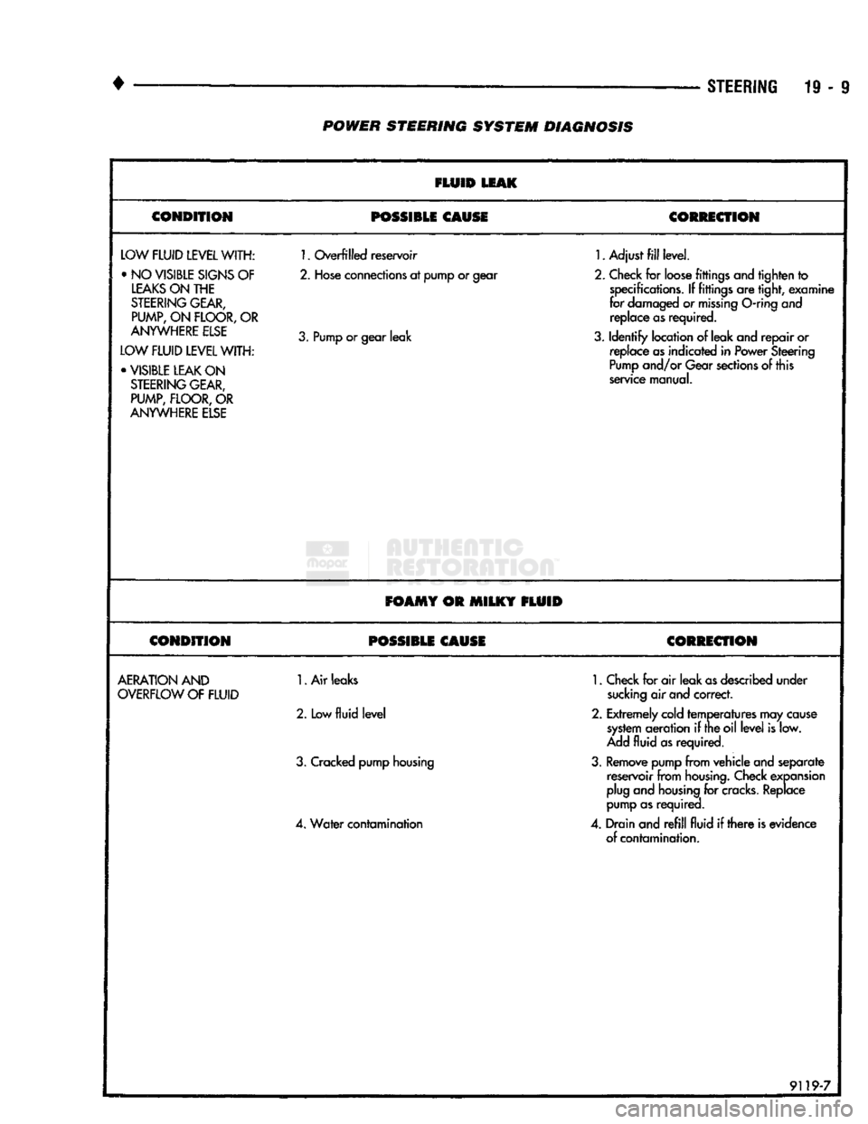
19-9 POWER STEERING SYSTEM DIAGNOSIS
FLUID
LEAK
CONDITION POSSIBLE CAUSE
CORRECTION
LOW
FLUID LEVEL
WITH: •NO
VISIBLE
SIGNS
OF
LEAKS ON THE
STEERING GEAR,
PUMP,
ON
FLOOR,
OR
ANYWHERE ELSE
LOW FLUID LEVEL WITH: • VISIBLE LEAK ON STEERING GEAR, PUMP, FLOOR, OR
ANYWHERE ELSE
1.
Overfilled reservoir
2.
Hose connections at pump or gear
3.
Pump or gear leak
1.
Adjust fill level.
2.
Check for loose fittings and tighten to specifications. If fittings are tight, examine
for damaged or missing
O-ring
and replace as required.
3.
Identify location of leak and repair or replace as indicated in Power Steering
Pump and/or Gear sections of this
service manual.
FOAMY OR MILKY FLUID
CONDITION POSSIBLE CAUSE CORRECTION
AERATION AND
OVERFLOW OF FLUID
1.
Air leaks
2.
Low
fluid level
3.
Cracked pump housing
4.
Water contamination
1.
Check for air leak as described under
sucking air and correct.
2.
Extremely cold temperatures may cause system aeration if the oil level is low.
Add fluid as required.
3.
Remove pump from vehicle and separate reservoir from housing. Check expansion
plug and housing for
cracks.
Replace
pump as required.
4.
Drain and refill fluid if there is evidence of contamination.
9119-7