DODGE TRUCK 1993 Service Repair Manual
Manufacturer: DODGE, Model Year: 1993, Model line: TRUCK, Model: DODGE TRUCK 1993Pages: 1502, PDF Size: 80.97 MB
Page 1321 of 1502
21
- 320
TRANSMISSION
0¥ERHAUL-46RH
LEVER
STRUT
J9121-18
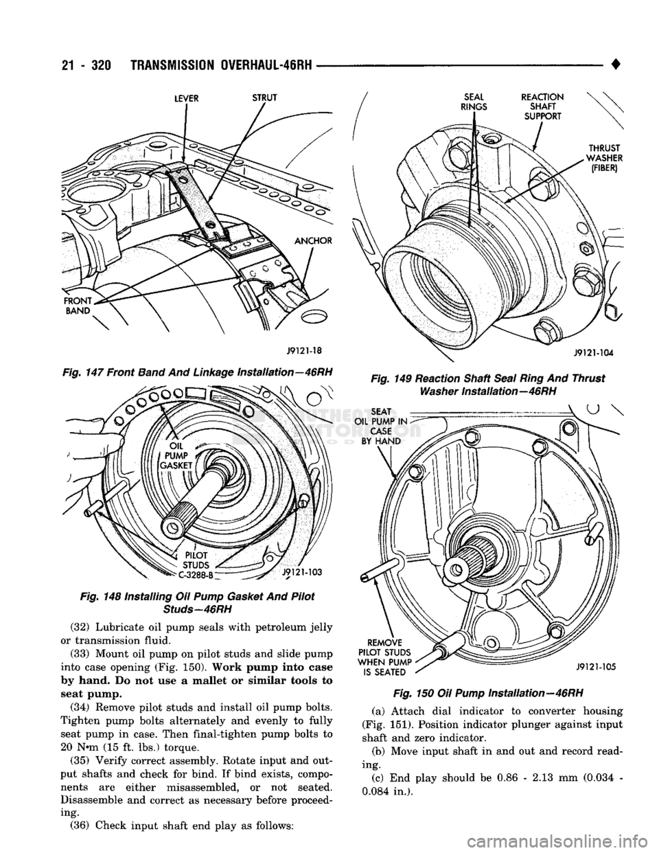
Fig.
147 Front
Band
And
Linkage
Installation—46RH
Fig.
148 Installing Oil
Pump
Gasket
And Pilot
Studs-46RH
(32) Lubricate oil pump seals with petroleum jelly
or transmission fluid.
(33) Mount oil pump on pilot studs and slide pump
into case opening (Fig. 150). Work pump into case
by hand. Do not use a mallet or similar tools to seat pump.
(34) Remove pilot studs and install oil pump bolts.
Tighten pump bolts alternately and evenly to fully seat pump in case. Then final-tighten pump bolts to 20 N-m (15 ft. lbs.) torque.
(35) Verify correct assembly. Rotate input and out
put shafts and check for bind. If bind exists, compo nents are either misassembled, or not seated.
Disassemble and correct as necessary before proceeding. •
Fig.
149 Reaction Shaft
Seal Ring
And Thrust
Washer
installation—46RH
Fig.
150 Oil
Pump
installation—46RH (a) Attach dial indicator to converter housing
(Fig. 151). Position indicator plunger against input
shaft and zero indicator.
(b) Move input shaft in and out and record read
ing.
(c) End play should be 0.86 - 2.13 mm (0.034 -
0.084 in.). (36) Check input shaft end play as follows:
Page 1322 of 1502
•
TRANSMISSION
0VERHAUL-4IRH
21 - 321 (d) If end play is incorrect, change output shaft
thrust washer, thrust plate, or front clutch thrust washer.
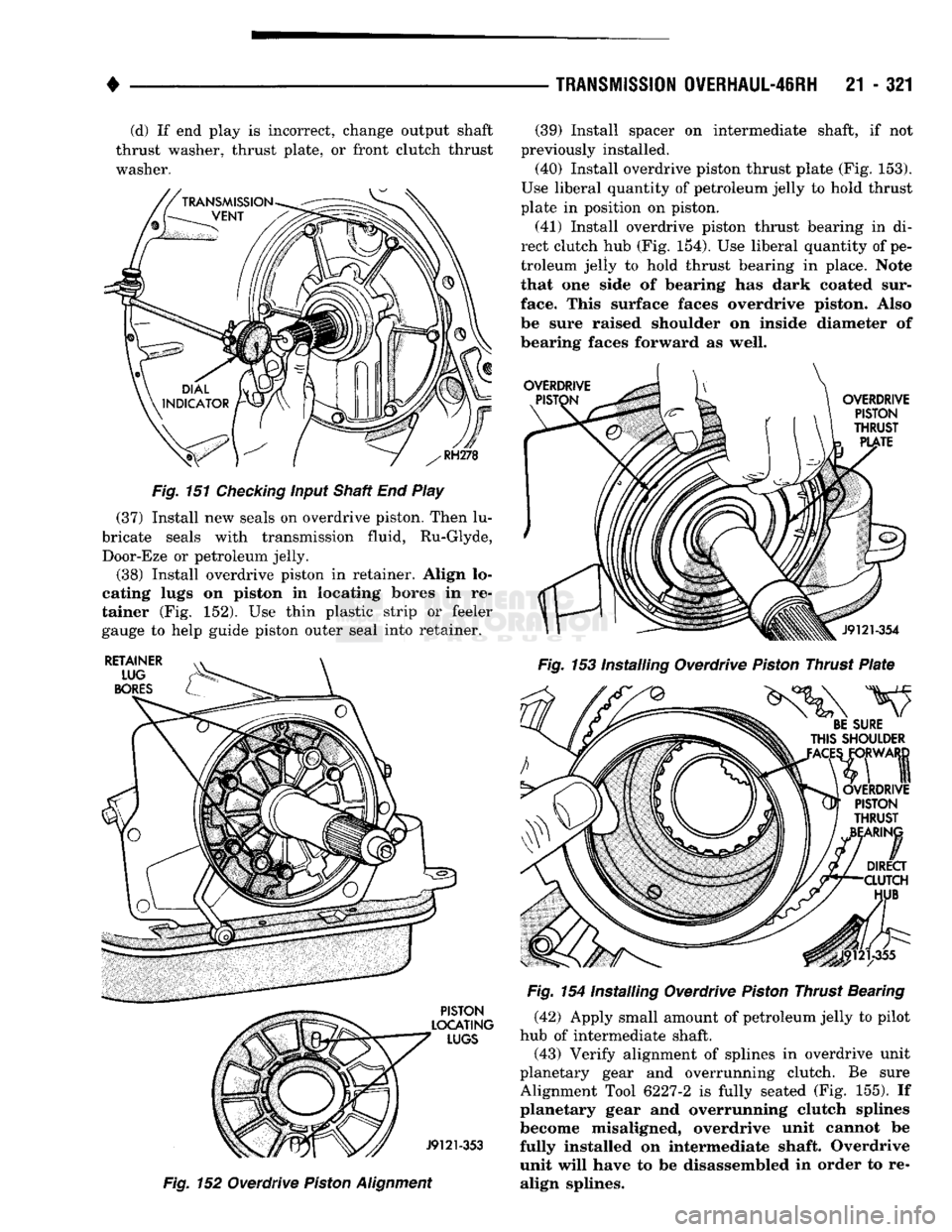
Fig.
151
Checking
input Shaft End Play
(37) Install new seals on overdrive piston. Then lu
bricate seals with transmission fluid, Ru-Glyde, Door-Eze or petroleum jelly.
(38) Install overdrive piston in retainer. Align lo
cating lugs on piston in locating bores in re
tainer (Fig. 152). Use thin plastic strip or feeler
gauge to help guide piston outer seal into retainer.
Fig.
152 Overdrive
Piston
Alignment
(39) Install spacer on intermediate shaft, if not
previously installed. (40) Install overdrive piston thrust plate (Fig. 153).
Use liberal quantity of petroleum jelly to hold thrust
plate in position on piston.
(41) Install overdrive piston thrust bearing in di
rect clutch hub (Fig. 154). Use liberal quantity of pe
troleum jelly to hold thrust bearing in place. Note
that one side of bearing has dark coated sur
face. This surface faces overdrive piston. Also
be sure raised shoulder on inside diameter of
bearing faces forward as well.
Fig.
153 Installing Overdrive
Piston
Thrust
Plate
Fig.
154 Installing Overdrive
Piston
Thrust Bearing (42) Apply small amount of petroleum jelly to pilot
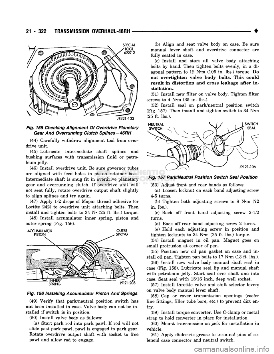
hub of intermediate shaft. (43) Verify alignment of splines in overdrive unit
planetary gear and overrunning clutch. Be sure
Alignment Tool 6227-2 is fully seated (Fig. 155). If
planetary gear and overrunning clutch splines
become misaligned, overdrive unit cannot be
fully installed on intermediate shaft. Overdrive
unit will have to be disassembled in order to re align splines.
Page 1323 of 1502
21
- 322
TRANSMISSION
OVERHAUL-46RH
•
J932M33
Fig.
155
Checking
Alignment
Of Overdrive Planetary
Gear
And Overrunning
Clutch
Splines—46RH
(44) Carefully withdraw alignment tool from over
drive unit.
(45) Lubricate intermediate shaft splines and
bushing surfaces with transmission fluid or petro leum jelly.
(46) Install overdrive unit. Be sure governor tubes
are aligned with feed holes in piston retainer boss.
Intermediate shaft is snug fit in overdrive planetary
gear and overrunning clutch. If overdrive unit will
not seat fully, rotate overdrive output shaft slightly
to align splines and try again.
(47) Apply 1-2 drops of Mopar thread adhesive (or
Loctite 242) to overdrive unit attaching bolts. Then
install and tighten bolts to 34 N» (25 ft. lbs.) torque.
(48) Install accumulator inner spring, piston and
outer spring (Fig. 156).
ACCUMULATOR
OUTER
Fig.
156 Installing
Accumulator
Piston
And
Springs
(49) Verify that park/neutral position switch has
not been installed in case. Valve body can not be in stalled if switch is in position.
(50) Install valve body as follows: (a) Start park rod into park pawl. If rod will not
slide past park pawl, pawl is engaged in park gear.
Rotate overdrive output shaft with socket to free
pawl and allow rod to engage. (b) Align and seat valve body on case. Be sure
manual lever shaft and overdrive connector are
fully seated in case.
(c) Install and start all valve body attaching
bolts by hand. Then tighten bolts evenly, in a di agonal pattern to 12 Nnn (105 in. lbs.) torque. Do
not overtighten valve body bolts. This could result in distortion and cross leakage after in stallation..
(51) Install new filter on valve body. Tighten filter
screws to 4 Nnn (35 in. lbs.).
(52) Install seal on park/neutral position switch
(Fig. 157). Then install and tighten switch to 34 Nnn
(25 ft. lbs.).
Fig.
157 Park/Neutral Position
Switch
Seal
Position
(53) Adjust front and rear bands as follows:
(a) Loosen locknut on each band adjusting screw
4-5 turns.
(b) Tighten both adjusting screws to 8 Nnn (72
in. lbs.).
(c) Back off front band adjusting screw 2-1/2
turns.
(d) Back off rear band adjusting screw 2 turns.
(e) Hold each adjusting screw in position and
tighten locknuts to 34 Nnn (25 ft. lbs.) torque.
(54) Install magnet in oil pan. Magnet goes on
small protrusion at corner of pan.
(55) Position new oil pan gasket on case and in
stall oil pan. Tighten pan bolts to 17 Nnn (13 ft. lbs.).
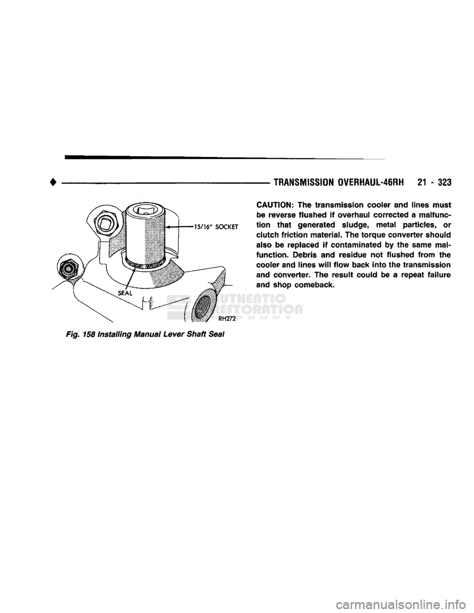
(56) Install new valve body manual shaft seal in
case (Fig. 158). Lubricate seal lip and manual shaft
with petroleum jelly. Start seal over shaft and into
case.
Seat seal with 15/16 inch, deep well socket.
(57) Install throttle valve and shift selector levers
on valve body manual lever shaft. (58) Cap or cover transmission openings (cooler
line fittings, filler tube bore, etc.) to prevent dirt en
try.
(59) Install torque converter. Use C-clamp or metal
strap to hold converter in place for installation. (60) Mount transmission on jack for installation in
vehicle.
(61) Apply dielectric grease to terminal pins of so
lenoid case connector and neutral switch.
Page 1324 of 1502
•
TRANSMISSION
OVERHAUL-46RH
21 - 323
CAUTION:
The transmission cooler and lines must
be reverse flushed if overhaul corrected a malfunc
tion
that
generated
sludge,
metal
particles, or clutch
friction
material. The torque converter should
also
be replaced if contaminated by the same mal
function. Debris and residue not flushed from the cooler and lines
will
flow back into the transmission
and converter. The result could be a
repeat
failure
and
shop
comeback. Fig. 158 Installing Manual Lever Shaft Seal
Page 1325 of 1502
21 - 324
OVERDRIVE
UNIT
OVERHAUL—42RH/46RH
•
OVERDRIVE
UNIT
OVERHAUL—42RH/46RH
INDEX
page
Overdrive
Geartrain
Assembly
333
Overdrive
Geartrain
Disassembly
326
Overdrive
Unit
Assembly
and
Adjustment
338
OVERDRIVE
UNIT
DISASSEMBLY
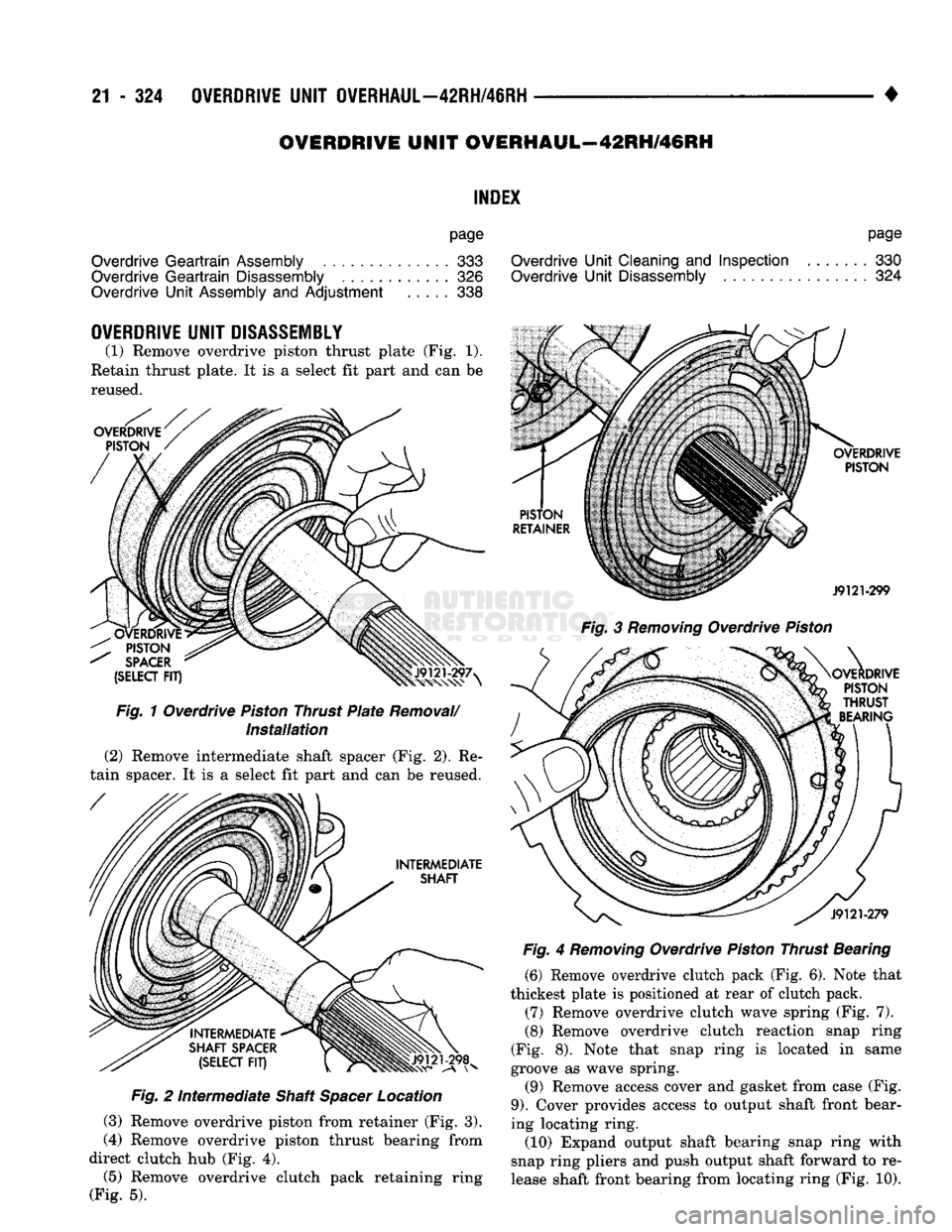
(1) Remove overdrive piston thrust plate (Fig. 1).
Retain thrust plate. It is a select fit part and can be reused.
Fig.
2
Intermediate
Shaft
Spacer
Location
(3) Remove overdrive piston from retainer (Fig. 3).
(4) Remove overdrive piston thrust bearing from
direct clutch hub (Fig. 4).
(5)
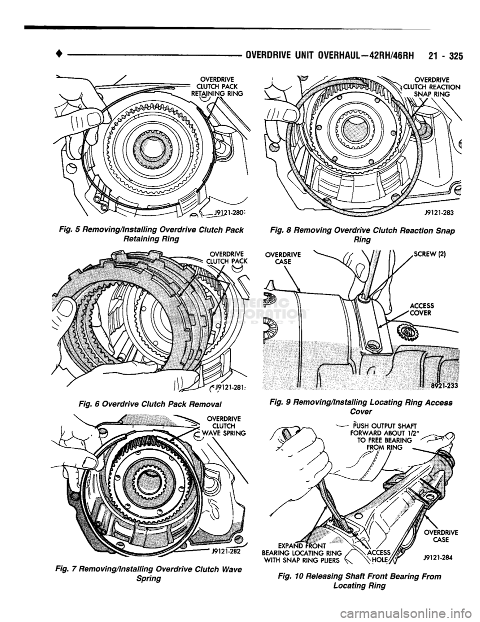
Remove overdrive clutch pack retaining ring
(Fig. 5).
page
Overdrive
Unit
Cleaning
and
Inspection
....... 330
Overdrive
Unit
Disassembly
324
Fig.
3
Removing
Overdrive
Piston
Fig.
4
Removing
Overdrive
Piston
Thrust Bearing (6) Remove overdrive clutch pack (Fig. 6). Note that
thickest plate is positioned at rear of clutch pack.
(7) Remove overdrive clutch wave spring (Fig. 7).
(8) Remove overdrive clutch reaction snap ring
(Fig. 8). Note that snap ring is located in same
groove as wave spring.
(9) Remove access cover and gasket from case (Fig.
9).
Cover provides access to output shaft front bear
ing locating ring.
(10) Expand output shaft bearing snap ring with
snap ring pliers and push output shaft forward to re
lease shaft front bearing from locating ring (Fig. 10).
Page 1326 of 1502
•
OVERDRIVE UNIT OVERHAUL—42RH/46RH 21 - 325
Fig. 5 Removing/Installing Overdrive Clutch Pack Retaining Ring
Fig. 6 Overdrive Clutch Pack Removal
Fig. 7 Removing/installing Overdrive Clutch Wave Spring Fig. 8 Removing Overdrive Clutch Reaction Snap
Ring
Fig. 9 Removing/Installing Locating Ring Access Cover
Fig. 10 Releasing Shaft Front Bearing From Locating Ring
Page 1327 of 1502
21 - 326
OVERDRIVE
UNIT
OVERHAUL—42RH/46RH
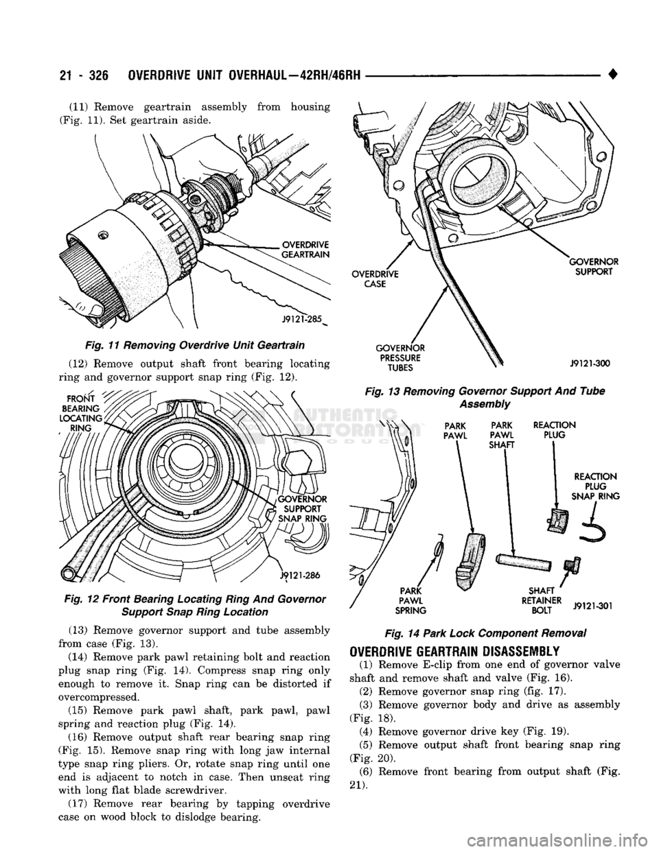
• (11) Remove geartrain assembly from housing
(Fig. 11). Set geartrain aside.
Fig. 11 Removing Overdrive Unit Geartrain
(12) Remove output shaft front bearing locating
ring and governor support snap ring (Fig. 12). Fig. 12 Front Bearing Locating Ring And Governor
Support Snap Ring Location (13) Remove governor support and tube assembly
from case (Fig. 13).
(14) Remove park pawl retaining bolt and reaction
plug snap ring (Fig. 14). Compress snap ring only enough to remove it. Snap ring can be distorted if
overcompressed.
(15) Remove park pawl shaft, park pawl, pawl
spring and reaction plug (Fig. 14). (16) Remove output shaft rear bearing snap ring
(Fig. 15). Remove snap ring with long jaw internal
type snap ring pliers. Or, rotate snap ring until one end is adjacent to notch in case. Then unseat ring
with long flat blade screwdriver.
(17) Remove rear bearing by tapping overdrive
case on wood block to dislodge bearing. Fig. 13 Removing Governor Support And Tube
Assembly
Fig. 14 Park Lock Component Removal
OVERDRIVE
GEARTRAIN
DISASSEMBLY
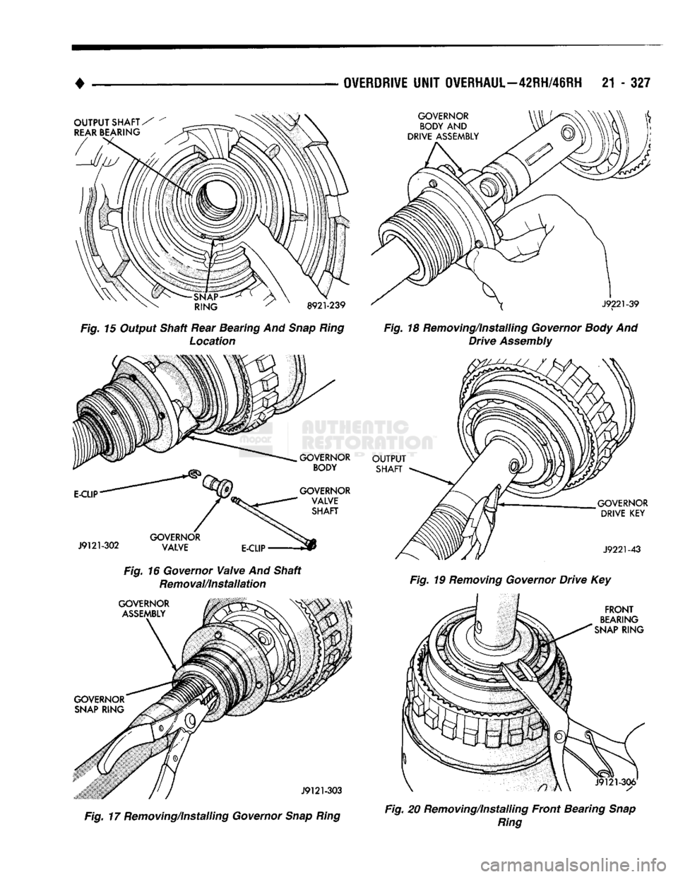
(1) Remove E-clip from one end of governor valve
shaft and remove shaft and valve (Fig. 16). (2) Remove governor snap ring (fig. 17). (3) Remove governor body and drive as assembly
(Fig. 18). (4) Remove governor drive key (Fig. 19).
(5) Remove output shaft front bearing snap ring
(Fig. 20). (6) Remove front bearing from output shaft (Fig.
21).
Page 1328 of 1502
OVERDRIVE
UNIT OVERHAUL—42RH/48RH
21 - 327
OUTPUT
SHAFT/
REAR
BEARING
•SNAP-
RING
8921-239
Fig. 15 Output Shaft Rear Bearing And
Snap Ring
Location
E-CLIP
J9121-302
GOVERNOR
BODY
GOVERNOR VALVE SHAFT
GOVERNOR VALVE E-CLIP-
Fig. 16 Governor
Valve
And Shaft Removal/Installation
GOVERNOR
ASSEMBLY
GOVERNOR
SNAP
RING
jmr
r / j9121-303
Fig. 17 Removing/Installing Governor
Snap Ring GOVERNOR
BODY
AND
DRIVE ASSEMBLY
J9221-39
Fig. 18 Removing/Installing Governor
Body
And Drive
Assembly
OUTPUT
SHAFT
GOVERNOR DRIVE
KEY
J9221-43
Fig. 19 Removing Governor Drive Key
FRONT
BEARING
SNAP
RING
Fig. 20 Removing/Installing Front Bearing
Snap
Ring
Page 1329 of 1502
21
- 328
OVERDRIVE UNIT OVERHAUL—42RH/46RH
•
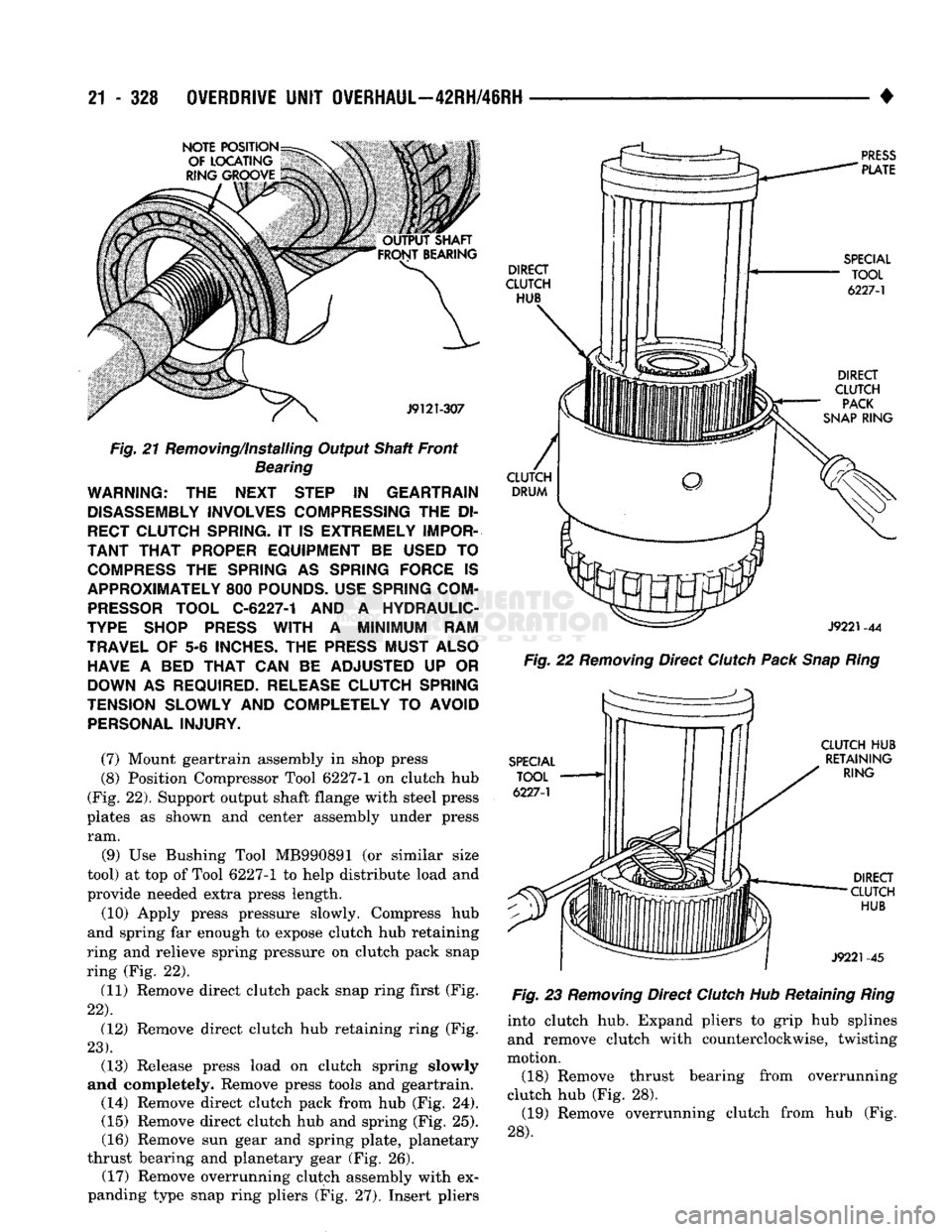
Fig.
21 Removing/Installing Output Shaft Front Bearing WARNING: THE NEXT STEP IN GEARTRAIN
DISASSEMBLY INVOLVES COMPRESSING THE DI
RECT CLUTCH SPRING. IT IS EXTREMELY IMPOR
TANT THAT PROPER EQUIPMENT BE USED TO COMPRESS THE SPRING AS SPRING FORCE IS
APPROXIMATELY 800 POUNDS. USE SPRING COM PRESSOR TOOL C-6227-1 AND A HYDRAULIC-
TYPE SHOP PRESS WITH A MINIMUM RAM
TRAVEL OF 5-6 INCHES. THE PRESS MUST ALSO HAVE A BED THAT CAN BE ADJUSTED UP OR
DOWN AS REQUIRED. RELEASE CLUTCH SPRING
TENSION SLOWLY AND COMPLETELY TO AVOID PERSONAL INJURY.
(7) Mount geartrain assembly in shop press
(8) Position Compressor Tool 6227-1 on clutch hub
(Fig. 22). Support output shaft flange with steel press
plates as shown and center assembly under press ram.
(9) Use Bushing Tool MB990891 (or similar size
tool) at top of Tool 6227-1 to help distribute load and
provide needed extra press length.
(10) Apply press pressure slowly. Compress hub
and spring far enough to expose clutch hub retaining
ring and relieve spring pressure on clutch pack snap
ring (Fig. 22).
(11) Remove direct clutch pack snap ring first (Fig.
22).
(12) Remove direct clutch hub retaining ring (Fig.
23).
(13) Release press load on clutch spring slowly
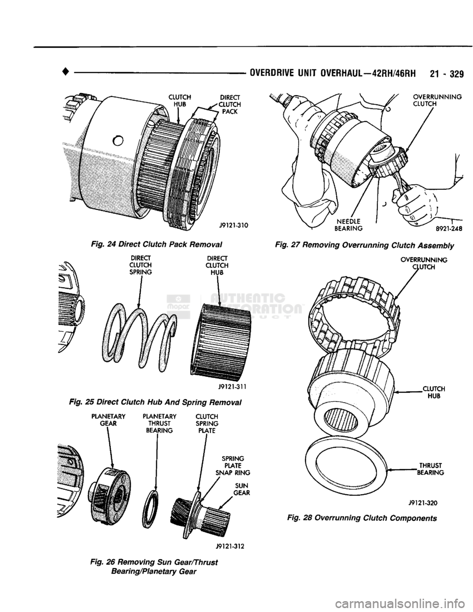
and completely. Remove press tools and geartrain. (14) Remove direct clutch pack from hub (Fig. 24). (15) Remove direct clutch hub and spring (Fig. 25).
(16) Remove sun gear and spring plate, planetary
thrust bearing and planetary gear (Fig. 26). (17) Remove overrunning clutch assembly with ex
panding type snap ring pliers (Fig. 27). Insert pliers
Fig.
22
Removing
Direct
Clutch
Pack
Snap
Ring
Fig.
23
Removing
Direct
Clutch
Hub Retaining
Ring
into clutch hub. Expand pliers to grip hub splines and remove clutch with counterclockwise, twisting
motion.
(18) Remove thrust bearing from overrunning
clutch hub (Fig. 28). (19) Remove overrunning clutch from hub (Fig.
28).
Page 1330 of 1502
•
OVERDRIVE
UNIT OVERHAUL—42RH/46RH 21 - 321
Fig. 24 Direct Clutch Pack Removal Fig. 27 Removing Overrunning Clutch Assembly
J9121-312
Fig. 26 Removing Sun Gear/Thrust Bearing/Planetary Gear