DODGE TRUCK 1993 Service Repair Manual
Manufacturer: DODGE, Model Year: 1993, Model line: TRUCK, Model: DODGE TRUCK 1993Pages: 1502, PDF Size: 80.97 MB
Page 1431 of 1502
23
- 48
BODY COMPONENTS
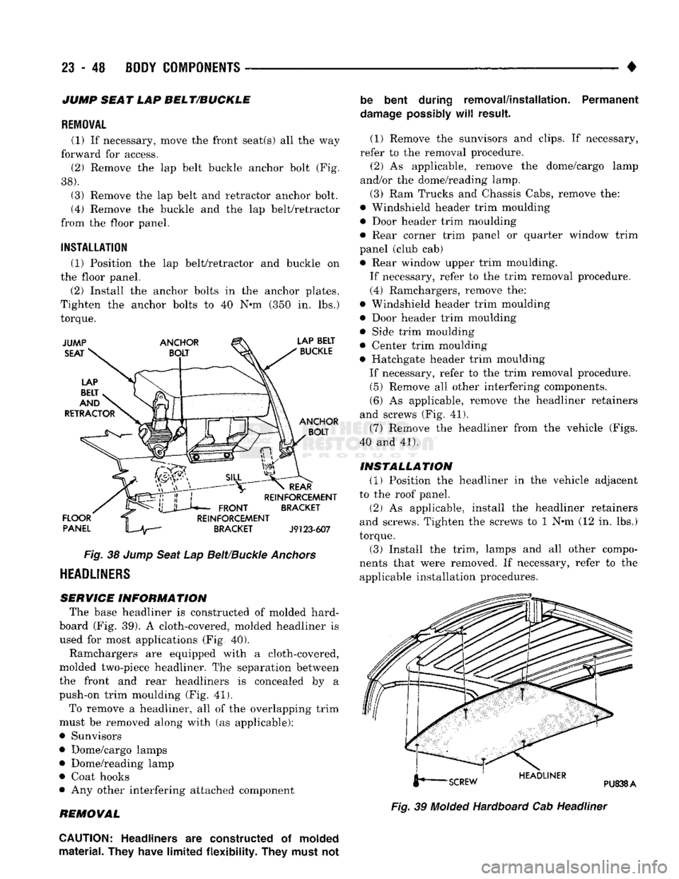
JUMP SEAT LAP BELT/BUCKLE
REMOVAL
(1) If necessary, move the front seat(s) all the way
forward for access. (2) Remove the lap belt buckle anchor bolt (Fig.
38).
(3) Remove the lap belt and retractor anchor bolt.
(4) Remove the buckle and the lap belt/retractor
from the floor panel.
INSTALLATION
(1) Position the lap belt/retractor and buckle on
the floor panel.
(2) Install the anchor bolts in the anchor plates.
Tighten the anchor bolts to 40 N*m (350 in. lbs.)
torque.
Fig.
38
Jump
Seat
Lap
Belt/Buckle
Anchors
HEADLINERS
SERVICE INFORMATION
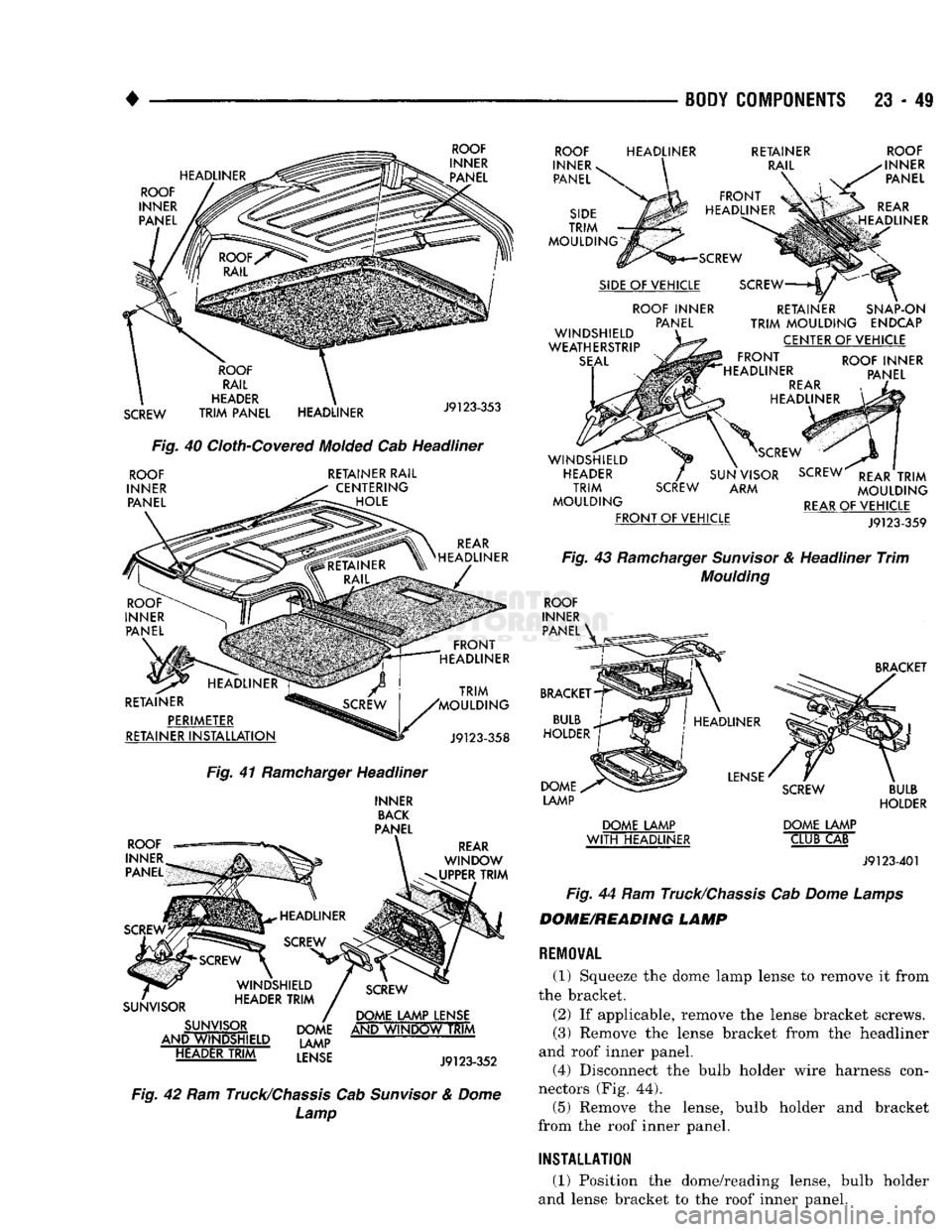
The base headliner is constructed of molded hard-
board (Fig. 39). A cloth-covered, molded headliner is
used for most applications (Fig, 40).
Ramchargers are equipped with a cloth-covered,
molded two-piece headliner. The separation between
the front and rear headliners is concealed by a
push-on trim moulding (Fig. 41).
To remove a headliner, all of the overlapping trim
must be removed along with (as applicable):
• Sunvisors
• Dome/cargo lamps • Dome/reading lamp
• Coat hooks
• Any other interfering attached component
REMOVAL be bent during removal/installation. Permanent
damage
possibly
will
result.
(1) Remove the sunvisors and clips. If necessary,
refer to the removal procedure. (2) As applicable, remove the dome/cargo lamp
and/or the dome/reading lamp.
(3) Ram Trucks and Chassis Cabs, remove the:
• Windshield header trim moulding
• Door header trim moulding
• Rear corner trim panel or quarter window trim
panel (club cab) • Rear window upper trim moulding.
If necessary, refer to the trim removal procedure.
(4) Ramchargers, remove the:
• Windshield header trim moulding
• Door header trim moulding
• Side trim moulding
• Center trim moulding
• Hatchgate header trim moulding
If necessary, refer to the trim removal procedure. (5) Remove all other interfering components.
(6) As applicable, remove the headliner retainers
and screws (Fig. 41).
(7) Remove the headliner from the vehicle (Figs.
40 and 41).
INSTALLATION
(1) Position the headliner in the vehicle adjacent
to the roof panel.
(2) As applicable, install the headliner retainers
and screws. Tighten the screws to 1 N*m (12 in. lbs.)
torque. (3) Install the trim, lamps and all other compo
nents that were removed. If necessary, refer to the applicable installation procedures.
Fig.
39
Molded
Hardboard Cab Headliner
CAUTION:
Headliners
are
constructed
of
molded
material. They have limited flexibility. They must
not
Page 1432 of 1502
•
^ ^ —
BODY COMPONENTS
23 - 49
HEADLINER ROOF
INNER PANEL
ROOF
INNER PANEL
SCREW
ROOF
RAIL
HEADER
TRIM
PANEL HEADLINER
J9123-353
Fig.
40
Cloth-Covered
Molded
Cab Headliner
ROOF
INNER PANEL RETAINER RAIL
CENTERING HOLE
REAR
HEADLINER
RETAINER PERIMETER
RETAINER
INSTALLATION
TRIM
'MOULDING
J9123-358
Fig.
41
Ramcharger
Headliner
INNER
BACK
PANEL
ROOF
—
INNER
PANEL
REAR
WINDOW
UPPER
TRIM
SUNVISOR SUNVISOR
AND WINDSHIELD HEADER
TRIM
DOME LAMP LENSE
DOME AND
WINDOW
TRIM
LAMP
LENSE
J9l
23-352
Fig.
42 Ram
Truck/Chassis
Cab
Sunvisor
&
Dome
Lamp
ROOF
INNER
v
PANEL
SIDE
TRIM
MOULDING
HEADLINER
RETAINER
RAIL
FRONT
HEADLINER
SCREW
SIDE
OF VEHICLE ROOF INNER PANEL
WINDSHIELD
WEATHERSTRIP
SEAL
ROOF
INNER PANEL
REAR
HEADLINER
SCREW
RETAINER SNAP-ON
TRIM
MOULDING
ENDCAP CENTER OF VEHICLE
FRONT
HEADLINER
REAR
HEADLINER ROOF INNER
PANEL WINDSHIELD
HEADER
TRIM
MOULDING
FRONT
OF VEHICLE
SCREW
SCREW
SUN VISOR SCREW
REAR
TRIM
ARM
MOULDING
REAR
OF VEHICLE
J9123-359
Fig.
43
Ramcharger
Sunvisor
& Headliner
Trim
Moulding
ROOF
INNER PANEL
BRACKET
BULB
HOLDER DOME
LAMP
BRACKET
HEADLINER
LENSE
DOME LAMP
WITH
HEADLINER
SCREW
DOME LAMP CLUB CAB
BULB
HOLDER
J9123-401
Fig.
44 Ram
Truck/Chassis
Cab
Dome
Lamps
DOME/READING LAMP
REMOVAL
(1) Squeeze the dome lamp lense to remove it from
the bracket.
(2) If applicable, remove the lense bracket screws.
(3) Remove the lense bracket from the headliner
and roof inner panel. (4) Disconnect the bulb holder wire harness con
nectors (Fig. 44). (5) Remove the lense, bulb holder and bracket
from the roof inner panel.
INSTALLATION
(1) Position the dome/reading lense, bulb holder
and lense bracket to the roof inner panel.
Page 1433 of 1502
23
- 50 BODY COMPONENTS — < ^ ^ • •
DOME LAMP DOME/READING LAMP
J9123-400
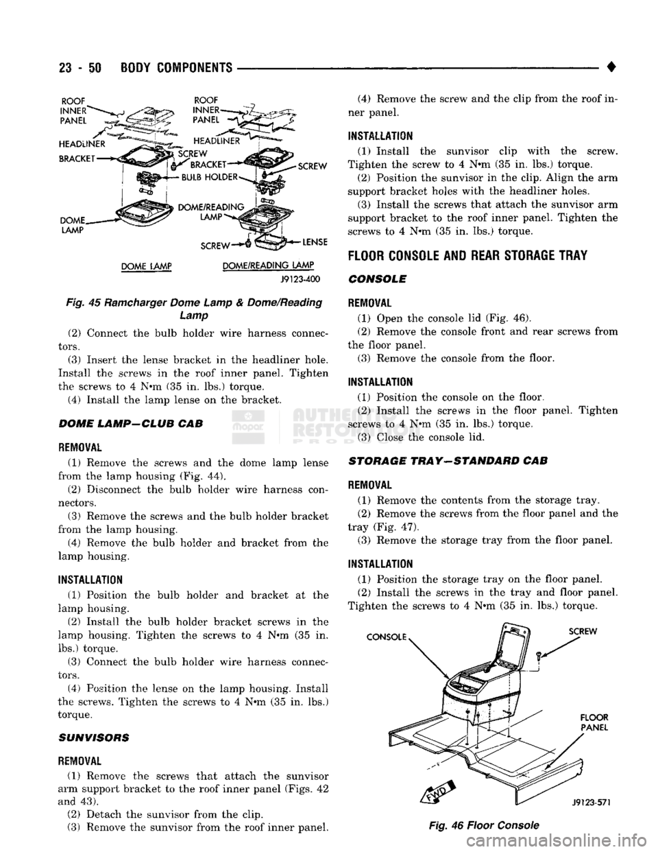
Fig.
45
Ramcharger
Dome Lamp
&
Dome/Reading Lamp (2) Connect
the
bulb holder wire harness connec
tors.
(3) Insert
the
lense bracket
in the
headliner hole.
Install
the
screws
in the
roof inner panel. Tighten
the screws
to 4 N#m (35 in. lbs.)
torque.
(4) Install
the
lamp lense
on the
bracket.
DOME LAMP-CLUB
CAB
REMOVAL
(1) Remove
the
screws
and the
dome lamp lense
from
the
lamp housing
(Fig. 44).
(2) Disconnect
the
bulb holder wire harness con
nectors.
(3) Remove
the
screws
and the
bulb holder bracket
from
the
lamp housing. (4) Remove
the
bulb holder
and
bracket from
the
lamp housing.
INSTALLATION
(1) Position
the
bulb holder
and
bracket
at the
lamp housing.
(2) Install
the
bulb holder bracket screws
in the
lamp housing. Tighten
the
screws
to 4 N°m (35 in.
lbs.) torque.
(3) Connect
the
bulb holder wire harness connec
tors.
(4) Position
the
lense
on the
lamp housing. Install
the screws. Tighten
the
screws
to 4 N#m (35 in. lbs.)
torque.
SUNVISORS
REMOVAL
(1) Remove
the
screws that attach
the
sunvisor
arm support bracket
to the
roof inner panel (Figs.
42
and
43).
(2) Detach
the
sunvisor from
the
clip.
(3) Remove
the
sunvisor from
the
roof inner panel. (4) Remove
the
screw
and the
clip from
the
roof
in
ner panel.
INSTALLATION
(1) Install
the
sunvisor clip with
the
screw.
Tighten
the
screw
to 4 N*m (35 in. lbs.)
torque, (2) Position
the
sunvisor
in the
clip. Align
the arm
support bracket holes with
the
headliner holes.
(3) Install
the
screws that attach
the
sunvisor
arm
support bracket
to the
roof inner panel. Tighten
the
screws
to 4
N*m
(35 in. lbs.)
torque.
FLOOR
CONSOLE AND
REAR STORAGE TRAY
CONSOLE
REMOVAL
(1) Open
the
console
lid (Fig. 46).
(2) Remove
the
console front
and
rear screws from
the floor panel.
(3) Remove
the
console from
the
floor.
INSTALLATION
(1) Position
the
console
on the
floor. (2) Install
the
screws
in the
floor panel. Tighten
screws
to 4 N«m (35 in. lbs.)
torque. (3) Close
the
console
lid.
STORAGE
TRAY-STANDARD
CAB
REMOVAL
(1) Remove
the
contents from
the
storage tray.
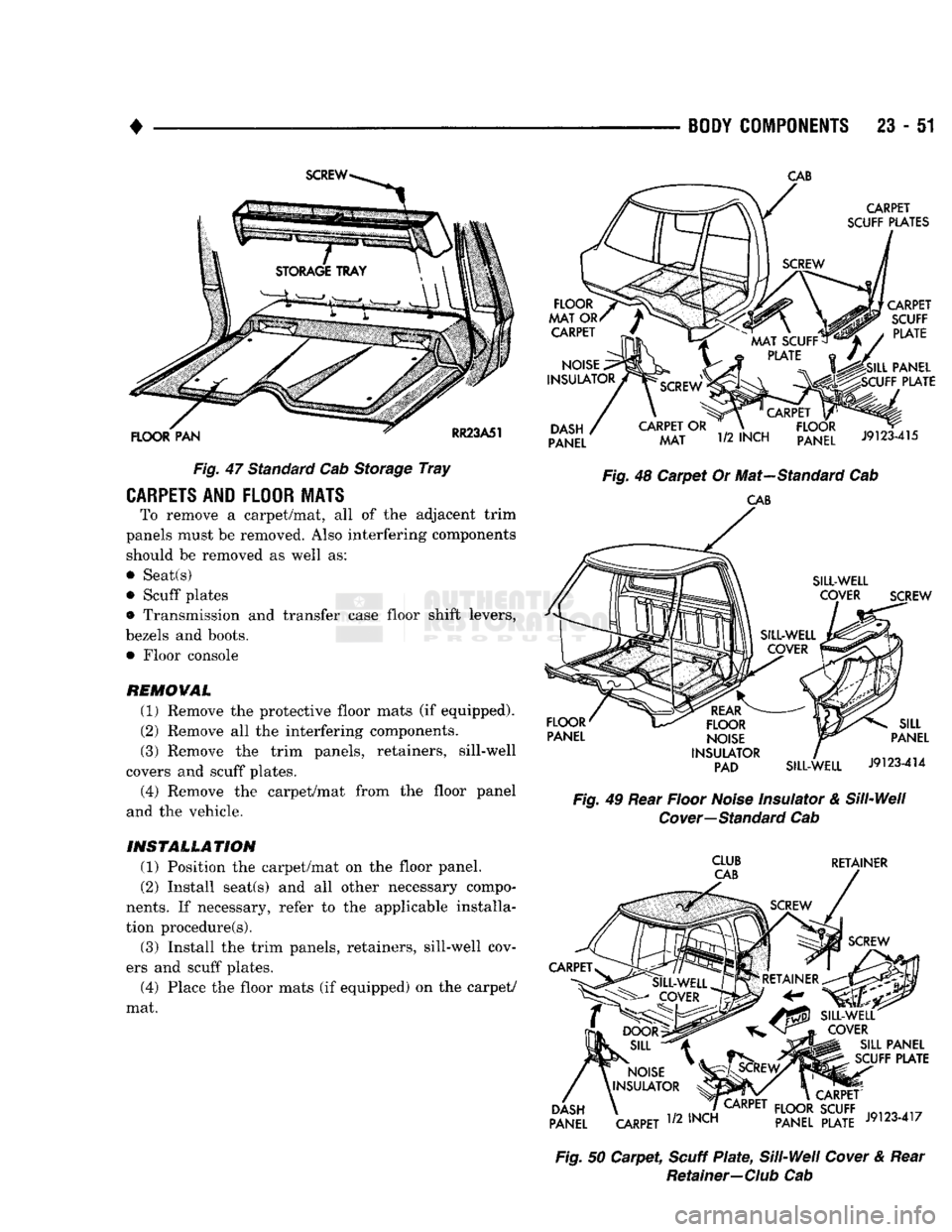
(2) Remove
the
screws from
the
floor panel
and the
tray
(Fig. 47).
(3) Remove
the
storage tray from
the
floor panel.
INSTALLATION
(1) Position
the
storage tray
on the
floor panel. (2) Install
the
screws
in the
tray
and
floor panel.
Tighten
the
screws
to 4 N«m (35 in. lbs.)
torque.
Fig.
46
Floor
Console
Page 1434 of 1502
•
Fig.
47 Standard Cab Storage
Tray
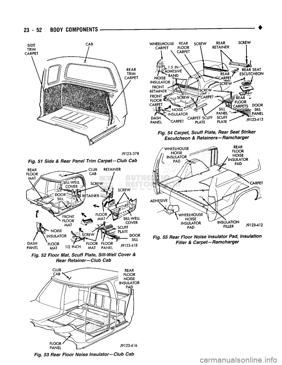
CARPETS
AND FLOOR HATS
To remove a carpet/mat, all of the adjacent trim
panels must be removed. Also interfering components should be removed as well as:
• Seat(s)
• Scuff plates
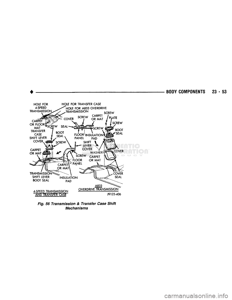
• Transmission and transfer case floor shift levers,
bezels and boots. • Floor console REMOWAL
(1) Remove the protective floor mats (if equipped).
(2) Remove all the interfering components.
(3) Remove the trim panels, retainers, sill-well
covers and scuff plates.
(4) Remove the carpet/mat from the floor panel
and the vehicle.
INSTALLATION
(1) Position the carpet/mat on the floor panel.
(2) Install seat(s) and all other necessary compo
nents.
If necessary, refer to the applicable installa
tion procedure(s).
(3) Install the trim panels, retainers, sill-well cov
ers and scuff plates.
(4) Place the floor mats (if equipped) on the carpet/
mat.
BODY COMPONENTS
23 - 51
Fig.
48 Carpet Or Mat—Standard Cab
CAB
Fig.
49 Rear Floor
Noise
Insulator & Sill-Well
Cover—Standard
Cab
CLUB
RETAINER
Fig.
50 Carpet,
Scuff
Plate,
Sill-Well
Cover
& Rear
Retainer—
Club
Cab
CAB
Page 1435 of 1502
23
- 52
BODY COMPONENTS
SIDE
TRIM
CARPET CAB
REAR
TRIM
CARPET J9123-378
Fig. 51 Side & Rear Panel
Trim
Carpet-Club Cab
REAR
FLOOR
MAT RETAINER
DASH
PANEL
FRONT
FLOOR MAT
NOISE
INSULATOR
FLOOR MAT
1/2
INCH
FLOOR FLOOR
MAT PANEL SILL-WELL
COVER
SCUFF PLATE DOOR SILL
J9123-418
Fig. 52 Floor Mat, Scuff
Plate,
Si
11-Wei
I
Cover & Rear Retainer—Club Cab
WHEELHOUSE
REAR
SCREW
CARPET FLOOR CARPET
REAR
RETAINER SCREW
REAR
SEAT
ESCUTCHEON
,1.5 IN
ADHESIVE
NOISE
^ND
INSULATOR
nj
FRONT
~*
RETAINERS
FRONT
;
FLOOR
!
CARPET .
NOISE:
INSULATOR
DASH
\
CARPET
SCUFF
PANEL XARPET PLATE PANEL
SCUFF PLATE
REAR
*
FLOOR
CARPETS
DOOR
SILL
PANEL
J9123-413
Fig. 54
Carpet,
Scuff
Plate,
Rear Seat Striker
Escutcheon
& Retainers-Ramcharger
REAR
FLOOR NOISE
INSULATOR PAD
CARPET
ADHESIVE
;
WHEELHOUSE
NOISE
INSULATOR PAD INSULATION
FILLER
J9123-412
Fig. 55 Rear Floor Noise Insulator Pad, Insulation
Filler
& Carpet—Ramcharger
CLUB
CAB
REAR
FLOOR NOISE
INSULATOR PAD
K52' \^ J9123-416
Fig. 53 Rear Floor Noise Insulator-Club Cab
Page 1436 of 1502
BODY COMPONENTS 23 - 53
HOLE
FOR
4-SPEED
TRANSMISSION TRANSMISSION
SCREW CARPET
OR
FLOOR*
MAT "
TRANSFER CASE
SHIFT
LEVER
COVER CARPET
OR MAT
TRANSMISSION
SHIFT
LEVER
BOOT
SEAL
COVER
SCREW
SEAL
CARPET
OR MAT
>QR
t
HOLE
FOR
TRANSFER
CASE
HOLE
FOR
A833
OVERDRIVE
SCREW
PLATE SCREW
SCREW
'
FLOOR1
INSULATION^,
PANEL PAD SHIFT
LEVER
COVER WASHER
SCREW
CARPET
FLOOR
OR MAT
PANEL BOOT
SEAL
INSULATION PAD
4-SPEED
TRANSMISSION
ANb
TRANSFER
CASE
A833
OVERDRIVE
TRANSMISSION
J9123-406
Fig. 56 Transmission &
Transfer
Case
Shift
Mechanisms
Page 1437 of 1502
23 - 54
BODY COMPONENTS
•
REFINISHING PROCEDURES
SERVICE
INFORMATION
Exterior vehicle body colors are identified on the
Body Code plate. The plate is attached to the top, right side of the cowl below the cowl grille. The color
code location is described in the manual introduction. OEM paint colors are generally available from all
of the major paint suppliers. They are supplied in the
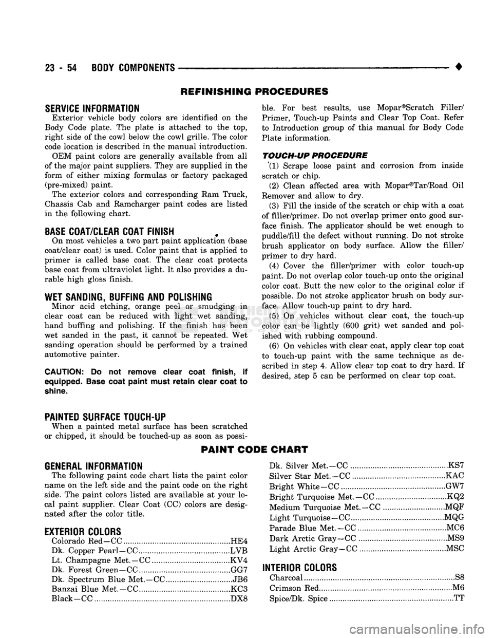
form of either mixing formulas or factory packaged (pre-mixed) paint. The exterior colors and corresponding Ram Truck,
Chassis Cab and Ramcharger paint codes are listed
in the following chart.
BASE
COAT/CLEAR COAT FINISH
On most vehicles a two part paint application (base
coat/clear coat) is used. Color paint that is applied to
primer is called base coat. The clear coat protects
base coat from ultraviolet light. It also provides a du
rable high gloss finish.
WET SANDING, BUFFING
AND
POLISHING
Minor acid etching, orange peel or smudging in
clear coat can be reduced with light wet sanding,
hand buffing and polishing. If the finish has been wet sanded in the past, it cannot be repeated. Wet sanding operation should be performed by a trained
automotive painter.
CAUTION:
Do not remove clear
coat
finish,
if
equipped.
Base
coat
paint
must
retain
clear
coat
to
shine.
ble.
For best results, use Mopar®Scratch Filler/
Primer, Touch-up Paints and Clear Top Coat. Refer
to Introduction group of this manual for Body Code
Plate information.
TOUCH-UP
PROCEDURE \l)
Scrape loose paint and corrosion from inside
scratch or chip.
(2) Clean affected area with Mopar®Tar/Road Oil
Remover and allow to dry.
(3) Fill the inside of the scratch or chip with a coat
of filler/primer. Do not overlap primer onto good sur
face finish. The applicator should be wet enough to
puddle/fill the defect without running. Do not stroke
brush applicator on body surface. Allow the filler/ primer to dry hard.
(4) Cover the filler/primer with color touch-up
paint. Do not overlap color touch-up onto the original color coat. Butt the new color to the original color if
possible. Do not stroke applicator brush on body sur
face.
Allow touch-up paint to dry hard.
(5) On vehicles without clear coat, the touch-up
color can be lightly (600 grit) wet sanded and pol
ished with rubbing compound.
(6) On vehicles with clear coat, apply clear top coat
to touch-up paint with the same technique as de scribed in step 4. Allow clear top coat to dry hard. If
desired, step 5 can be performed on clear top coat.
PAINTED SURFACE TOUCH-UP
When a painted metal surface has been scratched
or chipped, it should be touched-up as soon as possi-
PAINT CODE CHART
GENERAL
INFORMATION
The following paint code chart lists the paint color
name on the left side and the paint code on the right
side.
The paint colors listed are available at your lo
cal paint supplier. Clear Coat (CO colors are desig
nated after the color title.
EXTERIOR COLORS
Colorado Red-CC HE4
Dk. Copper Pearl-CC LVB Lt. Champagne Met.-CC KV4
Dk. Forest Green-CC GG7
Dk. Spectrum Blue Met.-CC JB6
Banzai Blue Met.-CC KC3
Black -CC DX8 Dk. Silver Met.-CC KS7
Silver Star Met.-CC KAC
Bright White-CC GW7
Bright Turquoise Met.-CC KQ2
Medium Turquoise Met.-CC MQF
Light Turquoise-CC MQG
Parade Blue Met.-CC... MC6
Dark Arctic Gray-CC MS9
Light Arctic Gray-CC MSC
INTERIOR COLORS
Charcoal S8
Crimson Red M6
Spice/Dk. Spice TT
Page 1438 of 1502
•
• —• •
HEATING
AND AIR
CONDITIONING
24 - 1 CONTENTS
page
CLIMATE CONTROL SYSTEM
............. 21
REFRIGERANT SYSTEM SERWICE
COMPRESSOR
SERWICE
(SD-709)
......... 21
PROCEDURES
.............
DIAGNOSTIC PROCEDURES
3
TORQUE SPECIFICATIONS
GENERAL INFORMATION
1
page
. 17
. 31
GENERAL INFORMATION
HEATER SYSTEM
All models use a Blend-Air type heater. Outside air
enters the heater through the cowl opening and
passes through a plenum chamber to the heater core. Air intake openings must be kept free of snow, ice and other obstructions for the heater system to pick
up sufficient outside air. A temperature control door
in the heater housing directs incoming air through
the heater core and/or the heater core bypass. The amount of blend (heated and non-heated air) is deter
mined by the setting of the temperature lever on the
instrument panel. Direction of the blended air is con
trolled by the HEAT-DEFROST lever on the instru ment panel. The blower switch and resistor block controls the
speed of the blower motor. This in turn controls the
velocity of the air flow from the heater outlets. The resistor block consists of 2 helical wound wire
resistors connected to terminals which are mechani cally attached to a glass-filled phenolic board. This
assembly is bolted to the plenum. The blower switch controls the blower motor speed
by selectively connecting the resistors in series to the
blower motor.
A self-adjusting clip, on each of 2 control cables has
been incorporated to simplify cable adjustment. This clip snaps onto the control cable core wire and will slide along the wire under a specific load to provide
an automatic cable adjustment.
AIR
CONDITIONING
SYSTEM
Air intake openings must be kept free of snow, ice
and other obstructions for the air conditioning sys
tem to pick up sufficient outside air.
COMPONENTS
• COMPRESSOR-The seven piston SD-709 com
pressor is used on all vehicles. This compressor com
presses the low pressure refrigerant vapor into a high pressure, high temperature vapor. • CLUTCH PULLEY AND COIL-These are
mounted on the compressor, providing a convenient
way to drive it and disengage it in accordance to the cooling needs.
• CONDENSER-The condenser is located in front
of the radiator. Its function is to cool the hot, high
pressure refrigerant gas causing it to condense into
high pressure liquid refrigerant.
• FILTER-DRIER—The filter-drier is used to remove
any traces of moisture from the refrigerant system.
This component incorporates the sight glass and the
high pressure relief valve.
• SIGHT GLASS-The sight glass is provided as a
diagnostic tool to observe refrigerant flow and indi cate refrigerant level. It is located at the top of the
filter drier.
• HIGH -PRESSURE RELIEF VALVE-This is a safety device designed to open automatically if the
system pressure reaches a predetermined level. This
will prevent system component damage. • EXPANSION (H) VALVE-The expansion (H)
valve is used to meter refrigerant into the evaporator
in accordance with cooling requirements. • EVAPORATOR COIL-The evaporator coil is lo
cated in the A/C unit. Its function is to cool and de-
humidify the air before it enters the vehicle. • FREEZE CONTROL-The main function of freeze
control is to prevent water on the evaporator coil face
from freezing which restricts the airflow. An elec
tronic temperature cycling switch is located on the
refrigerant plumbing (suction line) near the H-Valve.
The switch turns the compressor ON-OFF depending
on the temperature in the suction line. The switch is a sealed, specially calibrated unit. If found defective,
the switch must be replaced. • REFRIGERANT LINES-These lines are needed
to carry the refrigerant between the various system components.
• CONDENSATE DRAIN TUBE-Condensation
which accumulates on the bottom of the evaporator
HEATING
AND AIR
CONDITIONING
Page 1439 of 1502
24 - 2
HEATING
AND AIR
CONDITIONING
• housing is expelled through the molded rubber drain
tube into the engine compartment. The tube must be
kept open to prevent condensation from collecting in
the bottom of the housing.
The squeezed rubber flap at the drain tube tip is
designed to keep engine compartment air from enter ing into the system yet allow condensation to drain.
If the tip is not properly formed or has been dam
aged, the system will not drain properly. Therefore,
if the tube is damaged, it should be replaced.
• SERVICE VALVES—The service valves at the
compressor suction line and discharge tube are used
to test and service the refrigerant system. A special adapter (Tool C-4803) is required for performance
testing.
OPERATION The compressor increases the pressure and temper
ature of the refrigerant. The heated refrigerant vapor
is then pumped into the condenser where it cools by
giving off heat to air passing over the condenser fins.
As the refrigerant cools in the condenser, it con
denses into a liquid. Still under high pressure, the
liquid refrigerant passes into the receiver. The re
ceiver acts as a reservoir to furnish refrigerant to the
expansion (H) valve at all times. From the receiver,
the high pressure liquid refrigerant passes to the ex pansion (H) valve. The expansion (H) valve meters
refrigerant into the evaporator where a low pressure
is maintained by the suction side of the compressor.
As it enters the evaporator, the refrigerant immedi ately begins to boil by absorbing heat from the air
passing over the evaporator core. Having given up its
heat to boil the refrigerant, the air is cooled and
passes into the passenger compartment of the vehi
cle.
From the evaporator the vaporized refrigerant is
drawn back to the compressor to repeat the cycle. RADIATOR CAP
Air conditioned vehicles must be equipped with a
radiator cap having a holding pressure of 98-122 kPag (14-18 psig). Replace the radiator cap that does
not test within this specification.
CONDENSER Inspect the condenser for obstruction or foreign
matter. Clean if present.
Any obstruction to the free flow of air across the
condenser will decrease heat dissipation from the
condenser. This will in turn decrease the efficiency of
the condenser and decrease the evaporator's effi
ciency. These conditions result in increasing the dis
charge pressure and horsepower load on the engine.
The use of a bug screen is not recommended, it also
will decrease the free flow of air.
Inspect the condenser for bent or damaged fins.
The bent fins on the condenser deflect air flow and
decrease the condenser area.
BUG SCREENS Bug screens should NOT be installed on vehicles
equipped with air conditioning. A bug screen in
stalled in front of the condenser will reduce air flow
and air conditioner performance. Under severe heat
conditions a bug screen may cause the engine to
over-heat.
RESISTOR
BLOCK
The blower motor switch and resistor block, con
trols the speed of the blower motor. The resistor
block consists of 3 helical-wound wire resistors, con nected to terminals which are mechanically attached
to a phenolic board. This assembly is bolted to the
plenum.
The blower switch controls the blower motor speed
by selectively connecting in series one, two, three or none of the resistors to the blower motor.
Page 1440 of 1502
•
HEATING
AND AIR
CONDITIONING
24 - 3
DIAGNOSTIC
PROCEDURES
INDEX
page
page ..
7
General Information
3
.
. 3
Heating System Output
3
Air
Conditioning System
Blower
Motor
GENERAL
INFORMATION
The reason for owner dissatisfaction must be thor
oughly understood before any attempt is made to re
pair or replace any parts. It must be determined if
the condition is the heater system, the refrigerant system, air conditioning air flow or related to the
compressor. After confirming the condition, a func
tional test is suggested using the diagnostic charts.
After the condition has been properly diagnosed and corrected, check out the complete system to assure
that it is performing satisfactorily. The following charts have been developed for quick
reference. If the step by step method used is not com pletely understood, refer to the correct section of the Service Manual for detailed explanations.
HEATING
SYSTEM
OUTPUT
WARNING:
IF
VEHICLE
HAS
BEEN
RUN
RECENTLY,
WAIT
15
MINUTES
BEFORE
REMOVING
CAP, THEN
PLACE
A RAG
OVER
THE CAP AND
TURN
IT TO
THE
FIRST
STOP.
ALLOW
PRESSURE
TO
ESCAPE
THROUGH
THE
OVERFLOW
TUBE
AND
WHEN
THE
SYSTEM
STABILIZES,
REMOVE
THE CAP
COM
PLETELY.
Check the radiator coolant level, drive belt tension,
engine vacuum line connections, radiator air flow and radiator fan operation. Start engine and bring to
normal operating temperature (refer to Group 7,
Cooling System).
Engine coolant is provided to the heater system by
2 heater hoses. With engine idling at normal operat
ing temperature, set the heater control to maximum
heat, defrost and high blower setting. Using a test
thermometer, check the air temperature coming from
the defroster outlets (refer to Temperature Reference Chart).
Should the temperature not meet the minimum
values shown, refer to Heater Diagnosis (Mechanical)
for possible causes and corrections.
(1) Remove radiator pressure cap.
(2) Drain 1 pint of coolant from the radiator.
(3) Warm the engine to operating temperature by
idling for 20 minutes, with the pressure cap off. Idle longer if working outdoors in cold temperatures. (4) With the engine idling, place a thermometer
into the coolant in the radiator filler neck.
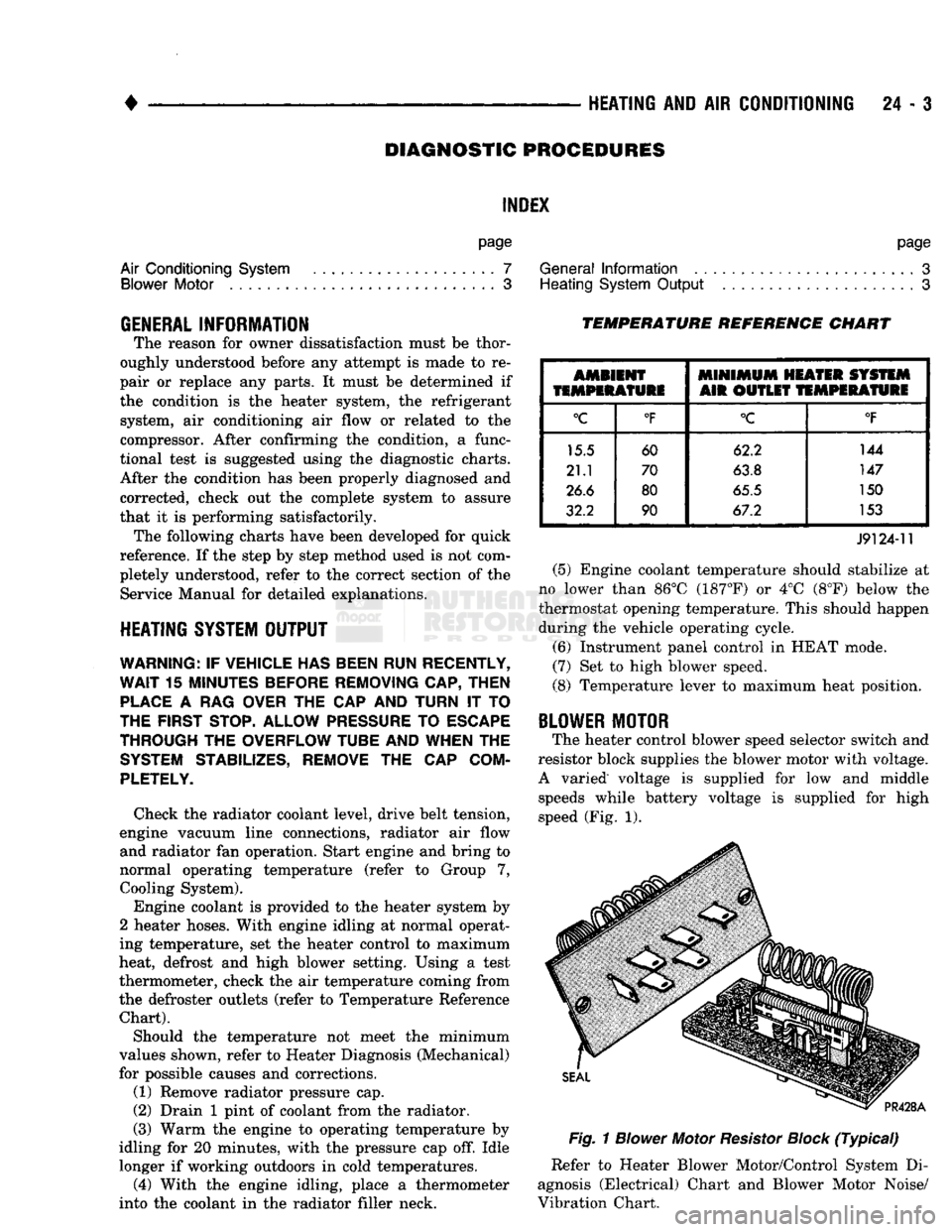
TEMPERATURE REFERENCE CHART
AMBIENT
MINIMUM
HEATER SYSTEM
TEMPERATURE
AIR OUTLET
TEMPERATURE
°C
°F
°C
°F
15.5 60 62.2 144
21.1 70
63.8 147
26.6 80
65.5 150
32.2 90 67.2 153
J9124-11
(5) Engine coolant temperature should stabilize at
no lower than 86°C (187°F) or 4°C (8°F) below the
thermostat opening temperature. This should happen during the vehicle operating cycle.
(6) Instrument panel control in HEAT mode.
(7) Set to high blower speed.
(8) Temperature lever to maximum heat position.
BLOWER
MOTOR
The heater control blower speed selector switch and
resistor block supplies the blower motor with voltage.
A varied voltage is supplied for low and middle speeds while battery voltage is supplied for high
speed (Fig. 1).
Fig.
1
Blower
Motor
Resistor
Block
(Typical)
Refer to Heater Blower Motor/Control System Di
agnosis (Electrical) Chart and Blower Motor Noise/
Vibration Chart.