DODGE TRUCK 1993 Service Repair Manual
Manufacturer: DODGE, Model Year: 1993, Model line: TRUCK, Model: DODGE TRUCK 1993Pages: 1502, PDF Size: 80.97 MB
Page 1421 of 1502
23 - 38
BODY COMPONENTS
— —
^—_____— —
•
PAWU
NUT
WASHER
SEALS
DASH
PANEL
SEAL
SUPPORT
BRACKET
NUT
INSTRUMENT
PANEL
RELEASE
HANDLE SCREW
RETAINER'
PARKING
BRAKE
SCREW LEVER J9123-568
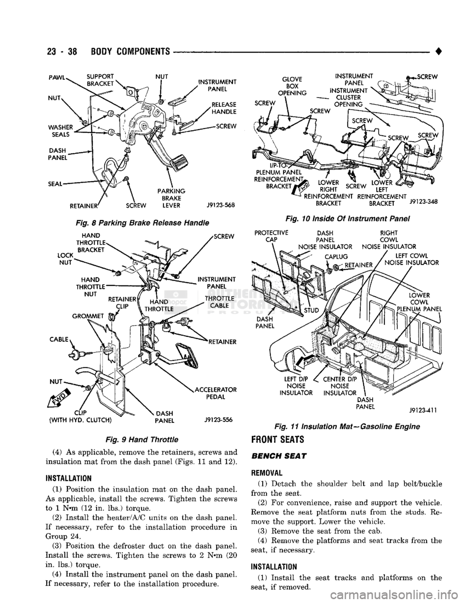
Fig.
8 Parking Brake
Release
Handle
LOCK
NUT
HAND
THROTTLE BRACKET SCREW
INSTRUMENT PANEL
HAND
^TfJlLE
>TTLE
RETAINER
CLIP
(WITH
HYD.
CLUTCH)
DASH
PANEL ACCELERATOR
PEDAL
J9123-556
Fig.
9
Hand
Throttle
(4) As applicable, remove the retainers, screws and
insulation mat from the dash panel (Figs. 11 and 12).
INSTALLATION
(1) Position the insulation mat on the dash panel.
As applicable, install the screws. Tighten the screws
to 1 N«m (12 in. lbs.) torque.
(2) Install the heater/A/C units on the dash panel.
If necessary, refer to the installation procedure in Group 24.
(3) Position the defroster duct on the dash panel.
Install the screws. Tighten the screws to 2 N*m (20
in. lbs.) torque.
(4) Install the instrument panel on the dash panel.
If necessary, refer to the installation procedure.
GLOVE
BOX
OPENING
SCREW INSTRUMENT
PANEL
INSTRUMENT
-
CLUSTER
OPENING
l/P-T
PLENUM
PANEL
REINFORCEMENT;
BRACKET
7
LOWER
RIGHT
SCREW
REINFORCEMENT REINFORCEMENT
BRACKET BRACKET J9123-348
Fig.
10
Inside
Of Instrument
Panel
PROTECTIVE
CAP DASH
PANEL
NOISE
INSULATOR
RIGHT
COWL
NOISE
INSULATOR
LEFT
COWL
NOISE
INSULATOR
LEFT
DIP
NOISE
INSULATOR
CENTER
DIP
NOISE
INSULATOR DASH
PANEL
J9123-411
Fig.
11 Insulation Mat—Gasoline
Engine
FRONT
SEATS BENCH SEAT
REMOVAL
(1) Detach the shoulder belt and lap belt/buckle
from the seat.
(2) For convenience, raise and support the vehicle.
Remove the seat platform nuts from the studs. Re
move the support. Lower the vehicle.
(3) Remove the seat from the cab.
(4) Remove the platforms and seat tracks from the
seat, if necessary.
INSTALLATION
(1) Install the seat tracks and platforms on the
seat, if removed.
Page 1422 of 1502
•
BODY
COMPONENTS
23 - 39
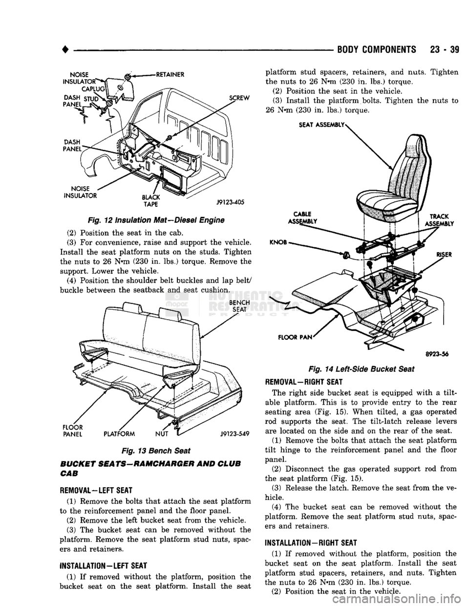
Fig.
12 Insulation Mat—Diesel
Engine
(2) Position the seat in the cab.
(3) For convenience, raise and support the vehicle.
Install the seat platform nuts on the studs. Tighten
the nuts to 26 Nnn (230 in. lbs.) torque. Remove the support. Lower the vehicle.
(4) Position the shoulder belt buckles and lap belt/
buckle between the seatback and seat cushion.
Fig.
13
Bench
Seat
BUCKET SEATS-RAMCHARGER AND CLUB CAB
REMOVAL—LEFT SEAT
(1) Remove the bolts that attach the seat platform
to the reinforcement panel and the floor panel.
(2) Remove the left bucket seat from the vehicle.
(3) The bucket seat can be removed without the
platform. Remove the seat platform stud nuts, spac ers and retainers. platform stud spacers, retainers, and nuts. Tighten
the nuts to 26 Nnn (230 in. lbs.) torque.
(2) Position the seat in the vehicle. (3) Install the platform bolts. Tighten the nuts to
26 Nnn (230 in. lbs.) torque.
8923-56
Fig.
14
Left-Side
Bucket Seat
REMOVAL—RIGHT SEAT
The right side bucket seat is equipped with a tilt-
able platform. This is to provide entry to the rear
seating area (Fig. 15). When tilted, a gas operated
rod supports the seat. The tilt-latch release levers are located on the side and on the rear of the seat.
(1) Remove the bolts that attach the seat platform
tilt hinge to the reinforcement panel and the floor
panel.
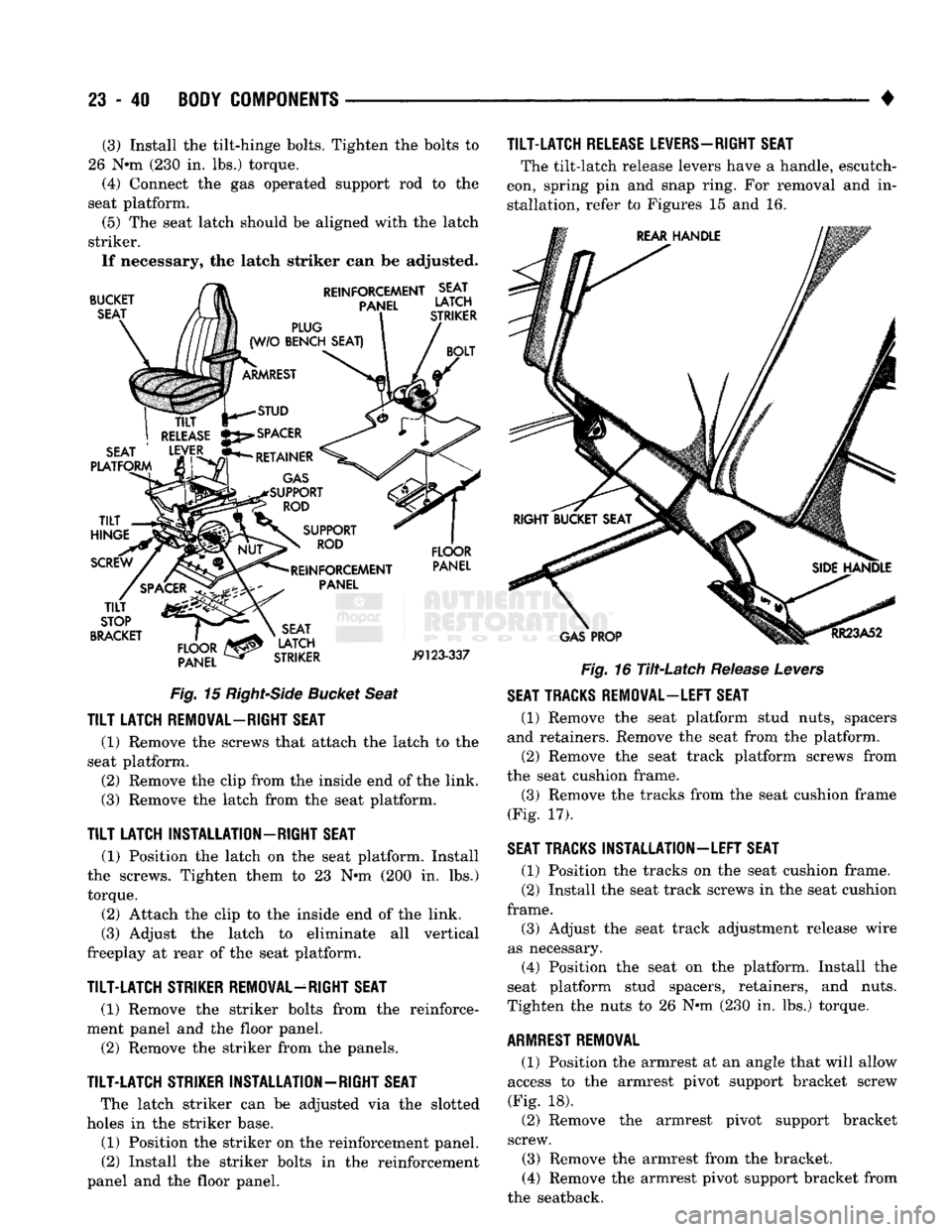
(2) Disconnect the gas operated support rod from
the seat platform (Fig. 15).
(3) Release the latch. Remove the seat from the ve
hicle.
(4) The bucket seat can be removed without the
platform. Remove the seat platform stud nuts, spac ers and retainers.
INSTALLATION-RIGHT
SEAT
(1) If removed without the platform, position the
bucket seat on the seat platform. Install the seat
platform stud spacers, retainers, and nuts. Tighten
the nuts to 26 Nnn (230 in. lbs.) torque.
(2) Position the seat in the vehicle.
INSTALLATION—LEFT
SEAT
(1) If removed without the platform, position the
bucket seat on the seat platform. Install the seat
Page 1423 of 1502
23
- 40
BODY COMPONENTS
• (3) Install the tilt-hinge bolts. Tighten the bolts to
26 N*m (230 in. lbs.) torque. (4) Connect the gas operated support rod to the
seat platform.
(5) The seat latch should be aligned with the latch
striker. If necessary, the latch striker can be adjusted.
TILT-LATCH
RELEASE LEVERS—RIGHT SEAT
The tilt-latch release levers have a handle, escutch
eon, spring pin and snap ring. For removal and in
stallation, refer to Figures 15 and 16.
BUCKET
SEAT REINFORCEMENT SEAT
PANEL
LATCH
PLUG
(W/O
BENCH SEAT)
ARMREST
TILT
I
RELEASE
SEAT
' LEVER
PLATFORM
TILT
HINGE
STUD
SPACER
RETAINER
GAS
SUPPORT ROD
SCREW
TILT
STOP
BRACKET
FLOOR
PANEL SUPPORT
ROD
REINFORCEMENT PANEL
SEAT
LATCH
STRIKER
FLOOR
PANEL
GAS
PROP
RR23A52
J9123-337
Fig. 15
Right-Side
Bucket
Seat
TILT
LATCH REMOVAL-RIGHT SEAT
(1) Remove the screws that attach the latch to the
seat platform. (2) Remove the clip from the inside end of the link.
(3) Remove the latch from the seat platform.
TILT
LATCH INSTALLATION-RIGHT SEAT
(1) Position the latch on the seat platform. Install
the screws. Tighten them to 23 N*m (200 in. lbs.) torque.
(2) Attach the clip to the inside end of the link.
(3) Adjust the latch to eliminate all vertical
freeplay at rear of the seat platform.
TILT-LATCH
STRIKER REMOVAL-RIGHT SEAT
(1) Remove the striker bolts from the reinforce
ment panel and the floor panel.
(2) Remove the striker from the panels.
TILT-LATCH
STRIKER INSTALLATION-RIGHT SEAT
The latch striker can be adjusted via the slotted
holes in the striker base.
(1) Position the striker on the reinforcement panel. (2) Install the striker bolts in the reinforcement
panel and the floor panel.
Fig.
16 Tilt-Latch Release Levers
SEAT TRACKS REMOVAL-LEFT SEAT
(1) Remove the seat platform stud nuts, spacers
and retainers. Remove the seat from the platform. (2) Remove the seat track platform screws from
the seat cushion frame. (3) Remove the tracks from the seat cushion frame
(Fig. 17).
SEAT TRACKS INSTALLATION-LEFT SEAT
(1) Position the tracks on the seat cushion frame.
(2) Install the seat track screws in the seat cushion
frame.
(3) Adjust the seat track adjustment release wire
as necessary.
(4) Position the seat on the platform. Install the
seat platform stud spacers, retainers, and nuts.
Tighten the nuts to 26 N*m (230 in. lbs.) torque.
ARMREST
REMOVAL
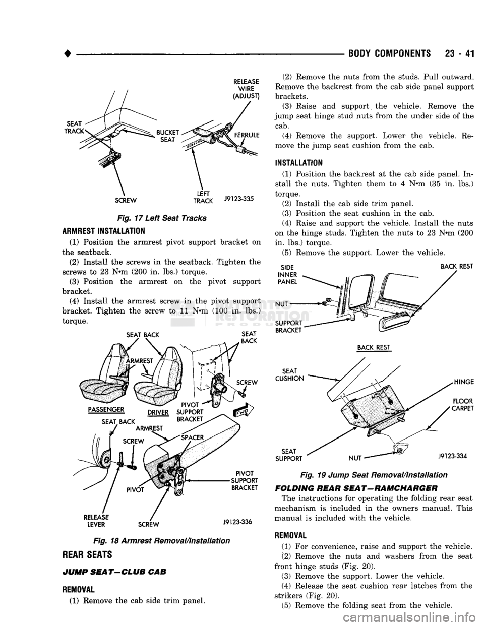
(1) Position the armrest at an angle that will allow
access to the armrest pivot support bracket screw
(Fig. 18). (2) Remove the armrest pivot support bracket
screw. (3) Remove the armrest from the bracket.
(4) Remove the armrest pivot support bracket from
the seatback.
Page 1424 of 1502
•
BODY COMPONENTS
23 - 41
RELEASE
SCREW TRACK
J9123"335 Fig. 17 Left Seat Tracks
ARMREST
INSTALLATION
(1) Position the armrest pivot support bracket on
the seatback.
(2) Install the screws in the seatback. Tighten the
screws to 23 N*m (200 in. lbs.) torque. (3) Position the armrest on the pivot support
bracket.
(4) Install the armrest screw in the pivot support
bracket. Tighten the screw to 11 N*m (100 in. lbs.) torque.
SEAT BACK SEAT
Fig. 18 Armrest Removal/Installation
REAR
SEATS
JUMP
SEAT-CLUB
CAB
REMOVAL
(1) Remove the cab side trim panel. (2) Remove the nuts from the studs. Pull outward.
Remove the backrest from the cab side panel support
brackets.
(3) Raise and support the vehicle. Remove the
jump seat hinge stud nuts from the under side of the
cab.
(4) Remove the support. Lower the vehicle. Re
move the jump seat cushion from the cab.
INSTALLATION
(1) Position the backrest at the cab side panel. In
stall the nuts. Tighten them to 4 N*m (35 in. lbs.)
torque.
(2) Install the cab side trim panel.
(3) Position the seat cushion in the cab.
(4) Raise and support the vehicle. Install the nuts
on the hinge studs. Tighten the nuts to 23 N#m (200 in. lbs.) torque.
(5) Remove the support. Lower the vehicle.
SIDE BACK REST
Fig. 19 Jump Seat Removal/installation
FOLDING HEAR SEAT-RAMCHARGER The instructions for operating the folding rear seat
mechanism is included in the owners manual. This
manual is included with the vehicle.
REMOVAL
(1) For convenience, raise and support the vehicle.
(2) Remove the nuts and washers from the seat
front hinge studs (Fig. 20).
(3) Remove the support. Lower the vehicle.
(4) Release the seat cushion rear latches from the
strikers (Fig. 20).
(5) Remove the folding seat from the vehicle.
Page 1425 of 1502
23
- 42
BODY
COMPONENTS
•
(6)
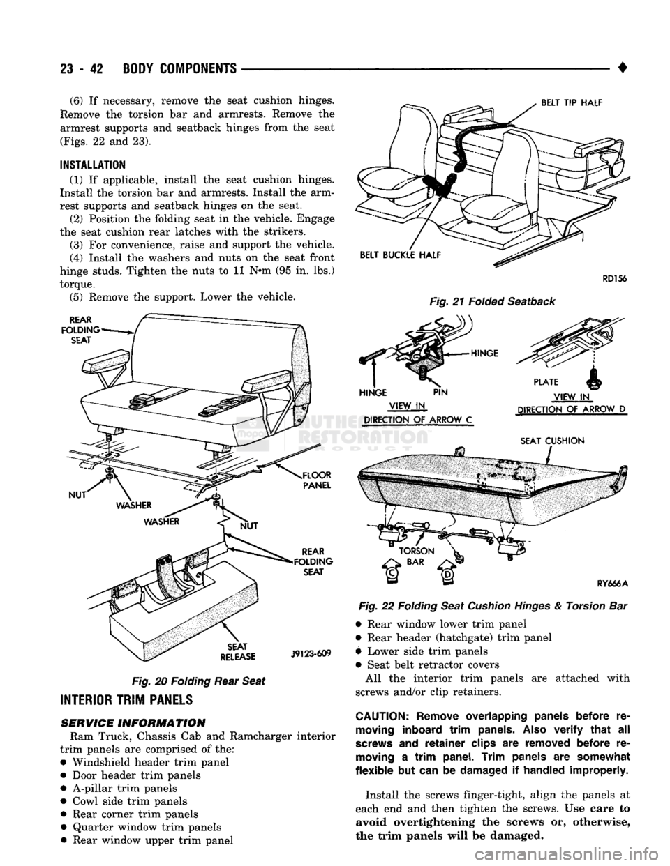
If necessary, remove the seat cushion hinges.
Remove the torsion bar and armrests. Remove the armrest supports and seatback hinges from the seat
(Figs.
22 and 23).
INSTALLATION
(1) If applicable, install the seat cushion hinges.
Install the torsion bar and armrests. Install the arm
rest supports and seatback hinges on the seat. (2) Position the folding seat in the vehicle. Engage
the seat cushion rear latches with the strikers.
(3) For convenience, raise and support the vehicle.
(4) Install the washers and nuts on the seat front
hinge studs. Tighten the nuts to 11 N»m (95 in. lbs.)
torque. (5) Remove the support. Lower the vehicle.
Fig.
20
Folding
Rear
Seat
INTERIOR
TRIM
PANELS
SERVICE
INFORMATION
Ram Truck, Chassis Cab and Ramcharger interior
trim panels are comprised of the: • Windshield header trim panel
• Door header trim panels
• A-pillar trim panels
• Cowl side trim panels • Rear corner trim panels • Quarter window trim panels • Rear window upper trim panel
RD156
Fig.
21 Folded
Seatback
Vltw IIN
DIRECTION
OF
ARROW
D
DIRECTION
OF
ARROW
C
SEAT
CUSHION
Fig.
22
Folding
Seat
Cushion
Hinges
& Torsion Bar
• Rear window lower trim panel
• Rear header (hatchgate) trim panel
§ Lower side trim panels
• Seat belt retractor covers All the interior trim panels are attached with
screws and/or clip retainers.
CAUTION:
Remove
overlapping
panels
before
re
moving
inboard
trim
panels.
Also
verify
that all
screws
and
retainer
clips
are
removed
before
re
moving
a
trim
panel.
Trim
panels
are
somewhat
flexible
but can be
damaged
if
handled
improperly.
Install the screws finger-tight, align the panels at
each end and then tighten the screws. Use care to avoid overtightening the screws or, otherwise,
the trim panels will be damaged.
Page 1426 of 1502
•
BODY
COMPONENTS
23 - 43
HINGE
AND LATCH
ARM REST SEAT BACK
NUT SUPPORT RY670
Fig. 23
Folding Seatback
Armrests,
Supports
& Hinges
COWL
SIDE
TRIM
PANEL
REMOVAL
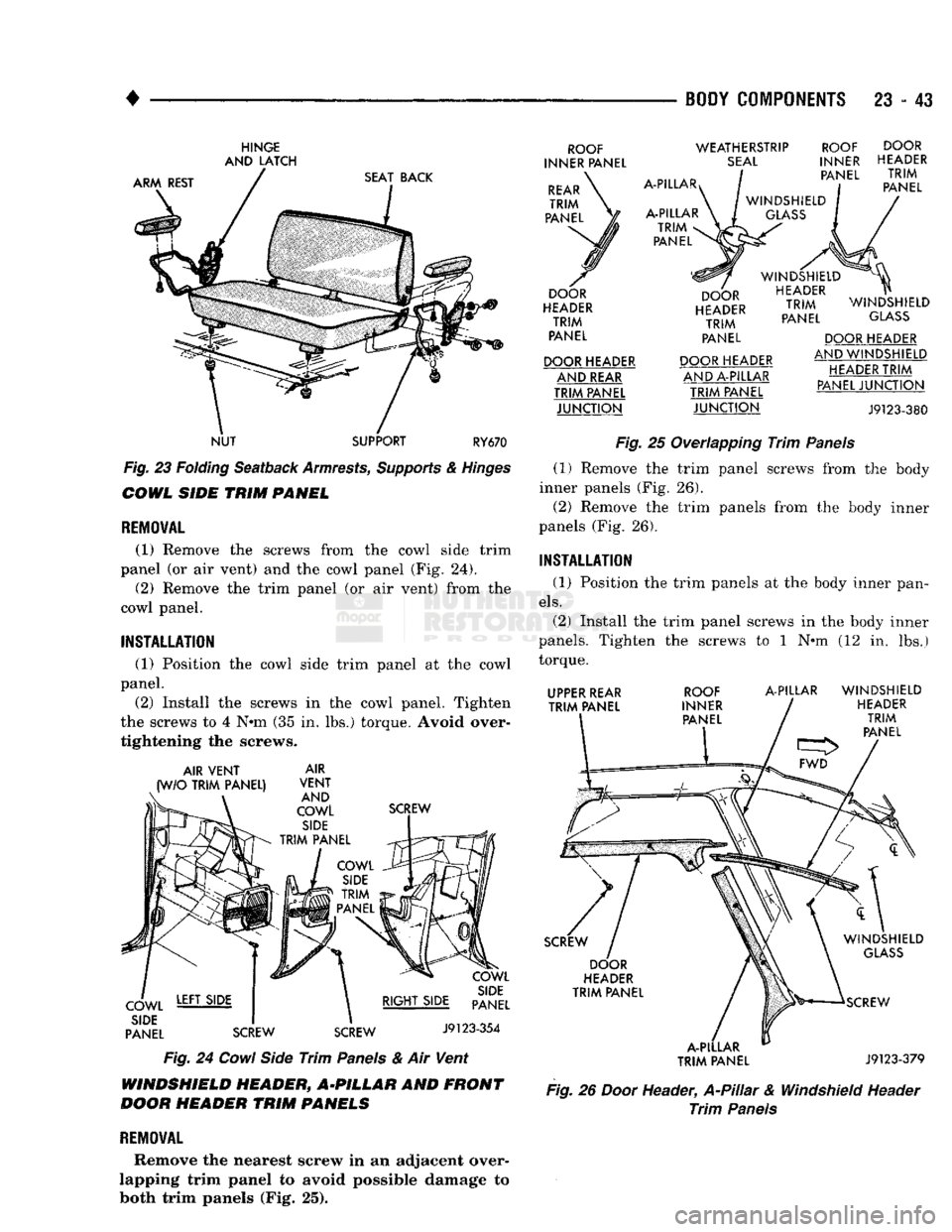
(1) Remove the screws from the cowl side trim
panel (or air vent) and the cowl panel (Fig. 24). (2) Remove the trim panel (or air vent) from the
cowl panel.
INSTALLATION
(1) Position the cowl side trim panel at the cowl
panel.
(2) Install the screws in the cowl panel. Tighten
the screws to 4 N»m (35 in. lbs.) torque. Avoid over
tightening the screws. AIR VENT
(W/O TRIM PANEL) AIR
VENT AND
COWL SIDE
TRIM PANEL SCREW
COWL
SIDE
TRIM
PANEL
COWL SIDE
PANEL COWL
SIDE
RIGHT SIDE PANEL
SCREW SCREW J9123-354
Fig.
24
Cowl
Side
Trim
Panels
& Air Vent WINDSHIELD HEADER, A-PILLAR AND
FRONT
DOOR
HEADER
TRIM
PANELS
REMOVAL
Remove the nearest screw in an adjacent over
lapping trim panel to avoid possible damage to both trim panels (Fig. 25). ROOF
INNER PANEL
REAR TRIM
PANEL WEATHERSTRIP
SEAL
A-PILLAR
A-PILLAR TRIM
<
PANEL DOOR
HEADER TRIM
PANEL
DOOR HEADER AND REAR
TRIM PANEL JUNCTION ROOF
INNER PANEL
WINDSHIELD GLASS
DOOR
HEADER TRIM
PANEL DOOR
HEADER TRIM
PANEL
WINDSHIELD HEADER TRIM
PANEL WINDSHIELD
GLASS DOOR HEADER
AND A-PILLAR TRIM PANEL JUNCTION DOOR HEADER
AND WINDSHIELD
HEADER TRIM
PANEL JUNCTION J9123-380
Fig.
25 Overlapping
Trim
Panels
(1) Remove the trim panel screws from the body
inner panels (Fig. 26).
(2) Remove the trim panels from the body inner
panels (Fig. 26).
INSTALLATION
(1) Position the trim panels at the body inner pan
els.
(2) Install the trim panel screws in the body inner
panels. Tighten the screws to 1 N»m (12 in. lbs.) torque. UPPER REAR
TRIM PANEL ROOF
INNER PANEL A-PILLAR WINDSHIELD
HEADER TRIM
PANEL FWD
SCREW DOOR
HEADER
TRIM PANEL
A-PILLAR
TRIM PANEL WINDSHIELD
GLASS
SCREW
J9123-379
Fig.
26
Door
Header,
A-PUIar
& Windshield Header
Trim
Panels
Page 1427 of 1502
23
- 44
BODY
COMPONENTS
•
CAB
REAR
CORNER/QUARTER
WINDOW
AND
REAR
WINDOW
UPPER/LOWER
TRIM
PANELS
REMOVAL
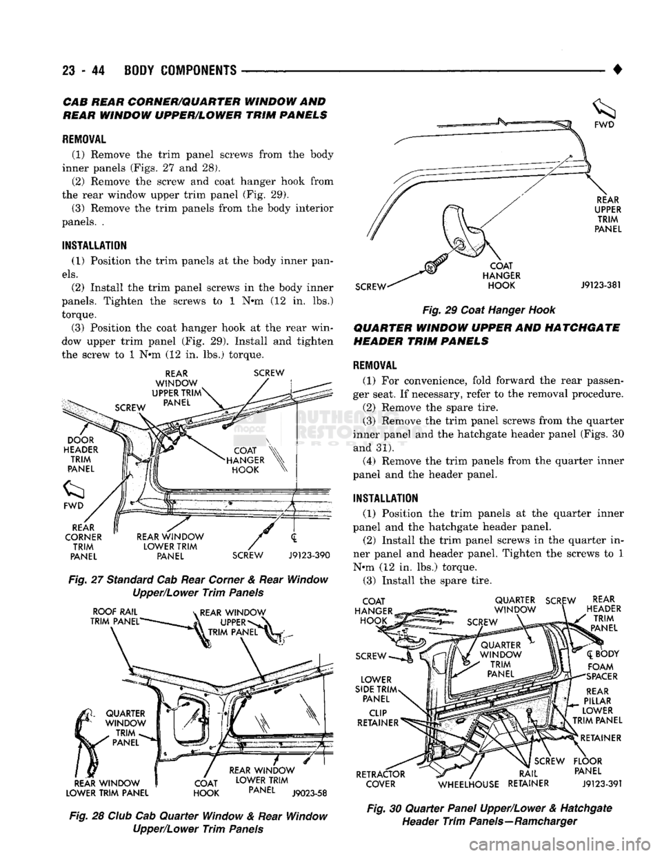
(1) Remove
the
trim panel screws from
the
body
inner panels (Figs.
27 and 28).
(2) Remove
the
screw
and
coat hanger hook from
the rear window upper trim panel
(Fig. 29).
(3) Remove
the
trim panels from
the
body interior
panels.
.
INSTALLATION
(1) Position
the
trim panels
at the
body inner pan
els.
(2) Install
the
trim panel screws
in the
body inner
panels. Tighten
the
screws
to 1 N»m (12 in. lbs.)
torque.
(3) Position
the
coat hanger hook
at the
rear win
dow upper trim panel
(Fig. 29).
Install
and
tighten
the screw
to 1 Nem (12 in. lbs.)
torque.
REAR
WINDOW
UPPER
TRIM
PANEL
SCREW
REAR
CORNER
TRIM
PANEL
REAR
WINDOW
LOWER
TRIM
PANEL
SCREW
J9123-390
Fig.
27
Standard Cab Rear Corner
&
Rear Window
Upper/Lower
Trim
Panels
ROOF
RAIL
TRIM
PANEL'
k
REAR
WINDOW
UPPER*
k TRIM
PANEL
REAR
WINDOW
LOWER
TRIM
PANEL
QUARTER
WINDOW
TRIM
PANEL
COAT
HOOK
REAR
WINDOW
LOWER
TRIM
PANEL
J9023-58
Fig.
28
Club
Cab
Quarter
Window
&
Rear Window
Upper/Lower
Trim
Panels
SCREW
COAT
HANGER
HOOK
REAR
UPPER
TRIM
PANEL
J9123-381
Fig.
29
Coat Hanger
Hook
QUARTER
WINDOW
UPPER
AND
HATCHGATE
HEADER
TRIM
PANELS
REMOVAL
(1)
For
convenience, fold forward
the
rear passen
ger seat.
If
necessary, refer
to the
removal procedure.
(2) Remove
the
spare tire.
(3) Remove
the
trim panel screws from
the
quarter
inner panel
and the
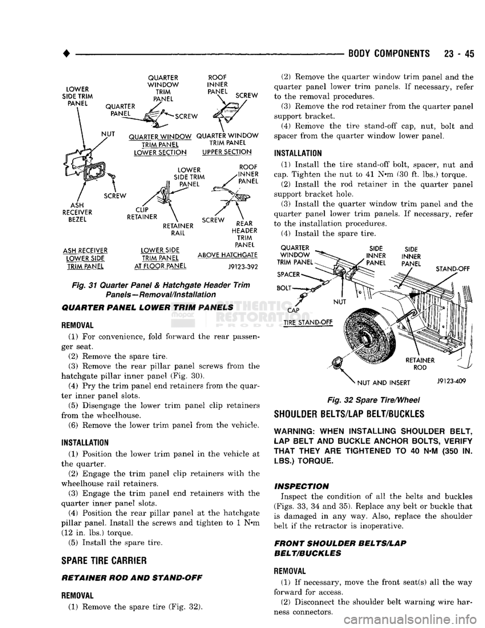
hatchgate header panel (Figs.
30
and
31).
(4) Remove
the
trim panels from
the
quarter inner
panel
and the
header panel.
INSTALLATION
(1) Position
the
trim panels
at the
quarter inner
panel
and the
hatchgate header panel.
(2) Install
the
trim panel screws
in the
quarter
in
ner panel
and
header panel. Tighten
the
screws
to 1
N*m
(12 in. lbs.)
torque.
(3) Install
the
spare tire.
COAT
HANGER
HOOK
SCREW
LOWER
SIDE
TRIM
PANEL
CLIP
RETAINER
RETRACTOR
COVER
QUARTER
SCREW
WINDOW
SCREW
REAR
HEADER
TRIM
PANEL
([BODY
FOAM
SPACER
REAR
PILLAR
LOWER
TRIM
PANEL
RETAINER
SCREW
FLOOR
RAIL
PANEL
WHEELHOUSE
RETAINER
J9123-391
Fig.
30
Quarter
Panel Upper/Lower
&
Hatchgate
Header
Trim
Panels—Ramcharger
Page 1428 of 1502
•
BODY
COMPONENTS 23 - 45
LOWER
SIDE TRIM PANEL
QUARTER
WINDOW
TRIM
PANEL
ROOF
INNER PANEL
\C SCREW
QUARTER PANEL SCREW
QUARTER WINDOW QUARTER WINDOW TRIM
PANEL
TRIM
PANEL
LOWER SECTION UPPER SECTION
SCREW
ASH
RECEIVER BEZEL
ASH RECEIVER LOWER SIDE TRIM PANEL CLIP
RETAINER LOWER
SIDE TRIM PANEL ROOF
INNER PANEL
RETAINER RAIL LOWER SIDE
TRIM PANEL
AT FLOOR PANEL SCREW REAR
HEADER TRIM
PANEL
ABOVE HATCHGATE
J9123-392 Fig.
31
Quarter
Panel & Hatchgate Header
Trim
Panels—Removal/Installation
QUARTER PANEL LOWER TRIM PANELS
REMOVAL
(1)
For
convenience, fold forward
the
rear passen
ger seat.
(2) Remove
the
spare tire. (3) Remove
the
rear pillar panel screws from
the
hatchgate pillar inner panel
(Fig. 30).
(4)
Pry the
trim panel end retainers from
the
quar
ter inner panel slots.
(5) Disengage
the
lower trim panel clip retainers
from
the
wheelhouse. (6) Remove
the
lower trim panel from
the
vehicle.
INSTALLATION
(1) Position
the
lower trim panel
in the
vehicle
at
the quarter.
(2) Engage
the
trim panel clip retainers with
the
wheelhouse rail retainers.
(3) Engage
the
trim panel
end
retainers with
the
quarter inner panel slots.
(4) Position
the
rear pillar panel
at the
hatchgate
pillar panel. Install
the
screws
and
tighten
to 1 N»m
(12
in. lbs.)
torque.
(5) Install
the
spare tire.
SPARE
TIRE
CARRIER
RETAINER
ROD AND
STAND-OFF
(2)
Remove
the
quarter window trim panel
and the
quarter panel lower trim panels.
If
necessary, refer
to
the
removal procedures. (3) Remove
the
rod retainer from
the
quarter panel
support bracket. (4) Remove
the
tire stand-off
cap, nut,
bolt
and
spacer from
the
quarter window lower panel.
INSTALLATION
(1) Install
the
tire stand-off bolt, spacer,
nut and
cap.
Tighten
the nut to 41 N»m (30 ft. lbs.)
torque.
(2) Install
the rod
retainer
in the
quarter panel
support bracket hole.
(3) Install
the
quarter window trim panel
and the
quarter panel lower trim panels.
If
necessary, refer
to
the
installation procedures.
(4)
Install
the
spare tire. QUARTER
WINDOW
TRIM PANEL
SPACER
BOLT SIDE
INNER
' PANEL SIDE
INNER
PANEL STAND-OFF
CAP
TIRE STAND-OFF
NUT
AND
INSERT J9123-409
Fig.
32 Spare Tire/Wheel
SHOULDER BELTS/LAP BELT/BUCKLES
WARNING:
WHEN
INSTALLING
SHOULDER BELT,
LAP
BELT
AND
BUCKLE ANCHOR BOLTS, VERIFY
THAT
THEY
ARE
TIGHTENED
TO 40 N-M (350 IN.
LBS.) TORQUE.
INSPECTION Inspect
the
condition
of all the
belts
and
buckles
(Figs.
33, 34 and
35). Replace
any
belt
or
buckle that
is damaged
in any way.
Also, replace
the
shoulder
belt
if
the retractor
is
inoperative.
FRONT SHOULDER BELTS/LAP
BELT/BUCKLES
REMOVAL
(1)
If
necessary, move
the
front seat(s)
all the way
forward
for
access. (2) Disconnect
the
shoulder belt warning wire har
ness connectors.
REMOVAL
(1) Remove
the
spare tire
(Fig. 32).
Page 1429 of 1502
23
- 46
BODY
COMPONENTS
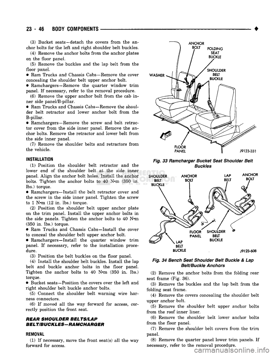
• (3) Bucket seats—detach the covers from the an
chor bolts for the left and right shoulder belt buckles.
(4) Remove the anchor bolts from the anchor plates
on the floor panel.
(5)
Remove the buckles and the lap belt from the
floor panel.
• Ram Trucks and Chassis Cabs—Remove the cover
concealing the shoulder belt upper anchor bolt.
• Ramchargers—Remove the quarter window trim
panel. If necessary, refer to the removal procedure.
(6) Remove the upper anchor bolt from the cab in
ner side panel/B-pillar.
• Ram Trucks and Chassis Cabs—Remove the shoul
der belt retractor and lower anchor bolt from the B-pillar.
• Ramchargers—Remove the screw and belt retrac
tor cover from the side inner panel. Remove the an chor bolts. Remove the retractor and lower belt from
the side inner panel.
(7) Remove the shoulder belts and retractors from
the vehicle.
INSTALLATION
(1) Position the shoulder belt retractor and the
lower end of the shoulder belt at the side inner
panel. Align the anchor bolt holes. Install the anchor
bolts.
Tighten the anchor bolts to 40 N*m (350 in. lbs.) torque.
• Ramchargers—Install the belt retractor cover and
the screw in the side inner panel. Tighten the screw
to 1 N»m (12 in. lbs.) torque.
(2) Position the shoulder belt upper anchor plate
on the trim panel. Install the upper anchor bolts in
the side panels. Tighten the anchor bolts to 40 N#m (350 in. lbs.) torque.
• Ram Trucks and Chassis Cabs—Install the cover
to conceal the shoulder belt upper anchor bolt.
• Ramchargers—Install the quarter window trim
panel. If necessary, refer to the installation proce
dure.
(3) Position the belt buckles on the floor panel.
(4) Install the shoulder belt buckles. Install the lap
belt and buckle anchor bolts in the floor panel.
Tighten the anchor bolts to 40 N«m (350 in. lbs.) torque.
• Bucket seats—Position the covers over the left and
right shoulder belt buckle anchor bolts.
(5) Connect the shoulder belt warning wire har
ness connectors. (6) If moved all the way forward for access, cor
rectly position the front seat.
REAR
SHOULDER
BELTS/LAP
BELT/BUCKLES-RAMCHARGER
REMOVAL
(1) If necessary, move the front seat(s) all the way
forward for access.
Fig.
33
Ramcharger
Bucket
Seat
Shoulder
Belt
Buckles
SHOULDER
ANCHOR
LAP
BELT
BUCKLE
.
J9123-608
Fig.
34
Bench
Seat
Shoulder
Belt
Buckle
& Lap
Belt/Buckle
Anchors
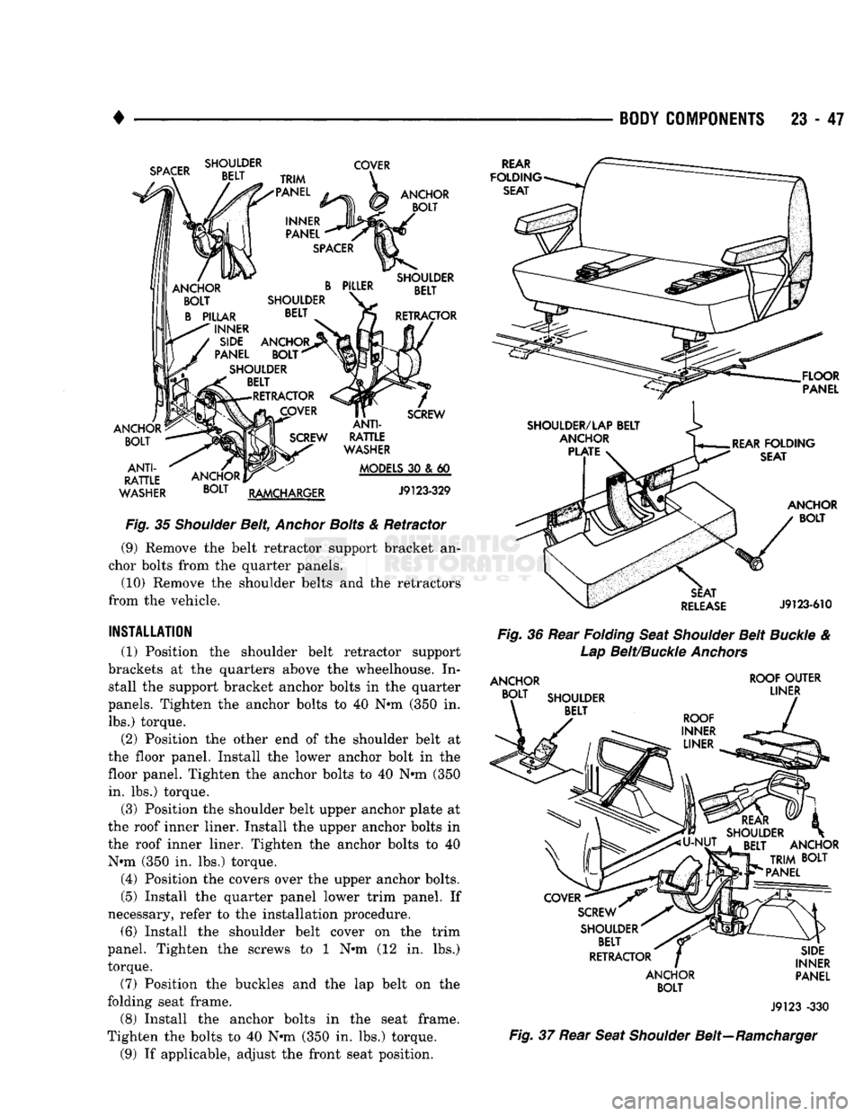
(2) Remove the anchor bolts from the folding rear
seat frame (Fig. 36). (3) Remove the buckles and the lap belt from the
folding seat frame. (4) Remove the covers concealing the shoulder belt
upper anchor bolt.
(5) Remove the shoulder belt upper anchor bolts
from the roof inner liner.
(6) Remove the shoulder belt lower anchor bolts
from the floor panel.
(7) Remove the shoulder belt covers from the trim
panel.
(8) Remove the quarter panel lower trim panels. If
necessary, refer to the removal procedure.
Page 1430 of 1502
•
BODY COMPONENTS 23 • 47
SPACER
SHOULDER
BELT COVER
TRIM
"PANEL
INNER
PANEL
SPACER
PILLER
SHOULDER BELT ANCHOR
BOLT
SHOULDER BELT
RETRACTOR
ANCHOR
BOLT
SHOULDER BELT
RETRACTOR
COVER
ANCHOR
BOLT
ANTI-
RATTLE
WASHER
SCREW
ANCHOR]
BOLT
RAMCHARGER
ANTI-
RATTLE
WASHER
MODELS
30 & 60
J9123-329
Fig.
35
Shoulder
Belt,
Anchor
Bolts
& Retractor (9) Remove the belt retractor support bracket an
chor bolts from the quarter panels.
(10) Remove the shoulder belts and the retractors
from the vehicle.
INSTALLATION
(1) Position the shoulder belt retractor support
brackets at the quarters above the wheelhouse. In stall the support bracket anchor bolts in the quarter
panels. Tighten the anchor bolts to 40 Nnn (350 in. lbs.) torque.
(2) Position the other end of the shoulder belt at
the
floor
panel. Install the lower anchor bolt in the
floor panel. Tighten the anchor bolts to 40 Nnn (350
in.
lbs.) torque.
(3) Position the shoulder belt upper anchor plate at
the roof inner liner. Install the upper anchor bolts in
the roof inner liner. Tighten the anchor bolts to 40 Nnn (350 in. lbs.) torque.
(4) Position the covers over the upper anchor bolts.
(5) Install the quarter panel lower trim panel. If
necessary, refer to the installation procedure. (6) Install the shoulder belt cover on the trim
panel. Tighten the screws to 1 Nnn (12 in. lbs.)
torque.
(7) Position the buckles and the lap belt on the
folding seat frame.
(8) Install the anchor bolts in the seat frame.
Tighten the bolts to 40 N-m (350 in. lbs.) torque.
(9) If applicable, adjust the front seat position.
REAR
FOLDING
SEAT
FLOOR
PANEL
ANCHOR
BOLT
SEAT
RELEASE
J9123-610
Fig.
36 Rear
Folding
Seat
Shoulder
Belt
Buckle
&
Lap
Belt/Buckle
Anchors
ANCHOR
BOLT
SHOULDER BELT ROOF
OUTER
LINER
COVER
•
SCREW"
SHOULDER^ BELT
RETRACTOR
ANCHOR
BOLT
SIDE
INNER PANEL
J9123 -330
Fig.
37 Rear
Seat
Shoulder
Belt—Ramcharger