DODGE TRUCK 1993 Service Repair Manual
Manufacturer: DODGE, Model Year: 1993, Model line: TRUCK, Model: DODGE TRUCK 1993Pages: 1502, PDF Size: 80.97 MB
Page 1441 of 1502
24
- 4
HEATING
AND
AIR
CONDITIONING
•
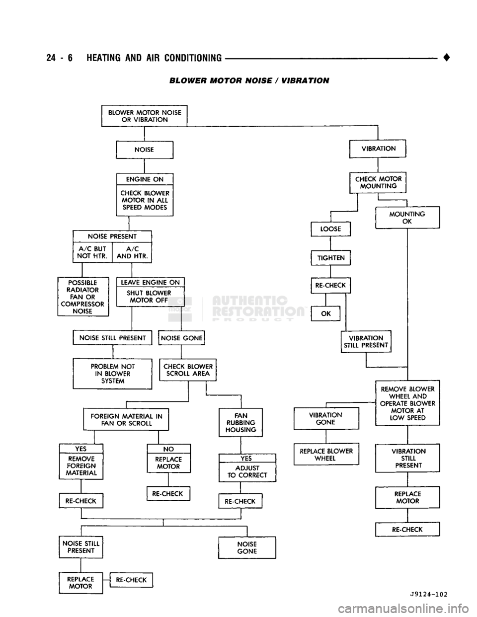
(1) Possible location or cause of blower motor vi
bration are as follows:
(a) Blower motor assembly loose in heater A/C
housing.
(b) Blower wheel loose on motor shaft.
(c) Blower wheel out of balance or bent.
(d) Blower motor defective.
(2) Possible location or cause of blower motor noise
are as follows: (To verify blower noise disconnect blower motor wire lead connector and operate heater
or A/C system. If noise goes away, proceed with pro
cedure.)
(a) Refer to vibration section of this procedure.
(b) Foreign material in Heater-A/C housing
around blower wheel.
(c) Blower wheel rubbing Heater-A/C housing.
(d) Blower motor defective.
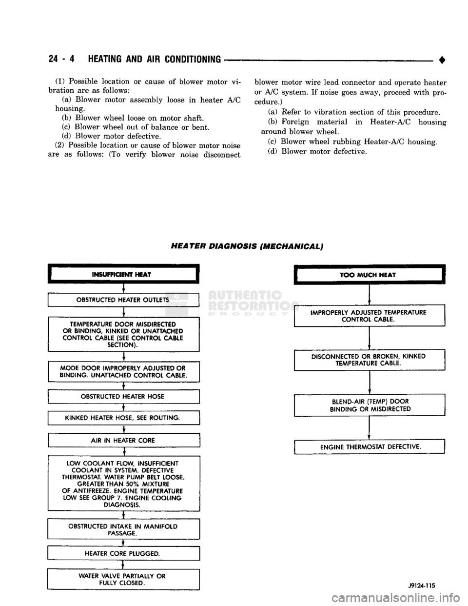
HEATER
DIAGNOSIS
(MECHANICAL)
INSUFFICIENT
HEAT
OBSTRUCTED HEATER OUTLETS
TEMPERATURE DOOR MISDIRECTED
OR BINDING, KINKED
OR
UNATTACHED
CONTROL CABLE (SEE CONTROL CABLE SECTION).
MODE DOOR IMPROPERLY ADJUSTED OR
BINDING. UNATTACHED CONTROL
CABLE.
±
OBSTRUCTED HEATER HOSE
•
KINKED HEATER HOSE, SEE ROUTING.
±
AIR
IN
HEATER CORE
LOW COOLANT FLOW, INSUFFICIENT COOLANT
IN
SYSTEM. DEFECTIVE
THERMOSTAT. WATER PUMP BELT LOOSE. GREATER
THAN
50%
MIXTURE
OF ANTIFREEZE. ENGINE TEMPERATURE LOW SEE GROUP
7.
ENGINE COOLING
DIAGNOSIS.
•
OBSTRUCTED INTAKE
IN
MANIFOLD
PASSAGE.
1_
HEATER CORE PLUGGED.
WATER VALVE PARTIALLY
OR
FULLY
CLOSED.
TOO
MUCH
HEAT
IMPROPERLY ADJUSTED TEMPERATURE CONTROL
CABLE.
DISCONNECTED
OR
BROKEN,
KINKED TEMPERATURE
CABLE.
BLEND-AIR
(TEMP)
DOOR
BINDING OR MISDIRECTED
ENGINE THERMOSTAT DEFECTIVE.
J9124-115
Page 1442 of 1502
![DODGE TRUCK 1993 Service Repair Manual
•
HEATING
AND
AIR
CONDITIONING
24 - 5 HEATER BLOWER MOTOR / CONTROL SYSTEM DIAGNOSIS (ELECTRICAL)
BLOWER
MOTOR
INOPERATIVE
]
[
INSPECT
FUSE
I- -*JT
FUSE
LOOKS
GOOD
CHECK
FOR DODGE TRUCK 1993 Service Repair Manual
•
HEATING
AND
AIR
CONDITIONING
24 - 5 HEATER BLOWER MOTOR / CONTROL SYSTEM DIAGNOSIS (ELECTRICAL)
BLOWER
MOTOR
INOPERATIVE
]
[
INSPECT
FUSE
I- -*JT
FUSE
LOOKS
GOOD
CHECK
FOR](/img/12/56922/w960_56922-1441.png)
•
HEATING
AND
AIR
CONDITIONING
24 - 5 HEATER BLOWER MOTOR / CONTROL SYSTEM DIAGNOSIS (ELECTRICAL)
BLOWER
MOTOR
INOPERATIVE
]
[
INSPECT
FUSE
I- -*JT
FUSE
LOOKS
GOOD
CHECK
FOR
STALLED MOTOR MOTOR
STALLED
REPLACE
MOTOR
REPLACE
FUSE
MOTOR
O.K. CHECK
FOR
SHORT
CORRECT
SHORT
REPLACE
FUSE
MOTOR
O.K. CHECK
FOR
SHORT
CORRECT
SHORT
REPLACE
FUSE
h
VOLTAGE
AT
BOTH
ENDS
OF
FUSE
CHECK
FOR
BATTERY VOLTAGE
AT BOTH ENDS
OF
FUSE
VOLTAGE
AT
BATTERY
SIDE
OF
FUSE ONLY
ATTACH
JUMPER
WIRE
BETWEEN
MOTOR GROUND WIRE
AND
BODY
OR
ENGINE
MOTOR
RUNS
LOCATE
AND
CORRECT
OPEN
CONNECTION
CHECK
BLOWER
REPLACE
MOTOR GROUND
FUSE
MOTOR DOES NOT
RUN
CHECK
MOTOR
CONTINUITY
IF MOTOR DOES NOT
RUN
REPLACE
MOTOR
MOTOR RUNS
ATTACH
JUMPER WIRE FROM
THE
MOTOR FEED WIRE
TO THE
POSITIVE POST
OF THE
BATTERY. MAKE SURE
THAT
MOTOR GROUND WIRE
IS
PROPERLY GROUNDED
FOR
THIS TEST.
REASSEMBLE
MOTOR WIRE CONNECTOR.
MAKE
SURE FEED
WIRE TERMINALS ARE
NOT BACKED
OUT OF
INSULATOR
OR OFF
CENTER
CHECK
RESISTOR
CONTINUITY
AND
RESISTOR
CONNECTIONS
VOLTAGE
AT
BATTERY LEAD CONNECTOR REMOVE WIRING CONNECTORS FROM RESISTOR TERMINALS.
MAKE
SURE
THAT
TERMINALS ARE
NOT
BACKED
OUT OF
INSULATOR.
CHECK
FOR
BATTERY VOLTAGE
IN
EACH
FAN
SWITCH POSITION.
REPLACE
SLOWER
SWITCH* VOLTAGE
IN
ALL SWITCH POSITIONS
CHECK
BLOWER SWITCH NO VOLTAGE
IN ONE OR
REPLACE
AND CONNECTIONS
MORE
SWITCH POSITIONS
RESISTOR
REMOVE WIRING CONNECTOR FROM SWITCH TERMINALS. MAKE
SURE
THE
TERMINALS ARE PROPERLY LOCKED
IN
SOCKETS
OF
INSULATOR. CHECK
FOR
BATTERY VOLTAGE
AT
BATTERY CONNECTOR
IN
THE INSULATOR.
BLOWER
MOTOR
DOES
NOT OPERATE AT
ALL SPEEDS
tfEl
J
RESISTOR
BLOCK
O.K.
CHECK
WIRING
CONNECTIONS AT
RESISTOR
BLOCK AND BLOWER SWITCH
IF DEFECTIVE,
REPLACE
BLOWER SWITCH INSPECT
BLOWER SWITCH INSPECT
RESISTOR
BLOCK
RESISTOR
BLOCK DEFECTIVE
REPLACE
RESISTOR BLOCK
*IF BLOWER SWITCH HAS FAILED DUE
TO
BURNING
OR
CHARRING,
CHECK
CURRENT DRAW
OF THE
BLOWER MOTOR.
J9124-101
Page 1443 of 1502
24
- 6
HEATING AND
AIR
CONDITIONING
BLOWER MOTOR NOISE / WIBRATION
BLOWER
MOTOR
NOISE
OR
VIBRATION
NOISE
VIBRATION
ENGINE
ON
CHECK BLOWER
MOTOR
IN
ALL
SPEED
MODES CHECK
MOTOR
MOUNTING
NOISE PRESEh
n
A/C BUT
NOT HTR. A/C
AND HTR.
POSSIBLE
RADIATOR FAN
OR
COMPRESSOR
NOISE LEAVE ENGINE
ON
SHUT
BLOWER
MOTOR
OFF
NOISE STILL PRESENT LO(
DSE
TIGHTEN
RE-CHECK
MOUNTING
OK
OK
NOISE GONE
PROBLEM
NOT
IN BLOWER SYSTEM
VIBRATION
STILL PRESENT
CHECK BLOWER
SCROLL
AREA
FOREIGN MATERIAL
IN
FAN
OR
SCROLL
YES
REMOVE
FOREIGN
MATERIAL FAN
RUBBING
HOUSING NO
REPLACE
MOTOR
RE-CHECK
VIBRATION
GONE
YES
A
TO
C
DJUST
ZORRECT RE-CHECK
REMOVE BLOWER
WHEEL AND
OPERATE BLOWER
MOTOR
AT
LOW SPEED REPLACE BLOWER
WHEEL
RE-CHECK
NOISE STILL PRESENT NOISE
GONE
VIBRATION
STILL
PRESENT
REPLACE
MOTOR
RE-CHECK REPLACE
MOTOR
RE-CHECK
J9124-102
Page 1444 of 1502
•
HEATING AND AIR CONDITIONING 24 - 7 AIR CONDITIONING SYSTEM
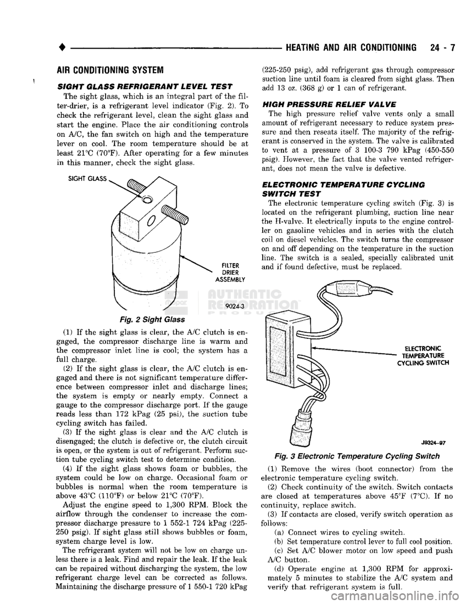
SIGHT GLASS REFRIGERANT LEWEL TEST The sight glass, which is an integral part of the fil
ter-drier, is a refrigerant level indicator (Fig. 2). To check the refrigerant level, clean the sight glass and
start the engine. Place the air conditioning controls
on A/C, the fan switch on high and the temperature lever on cool. The room temperature should be at
least 21°C (70°F). After operating for a few minutes
in this manner, check the sight glass.
SIGHT
GLASS
FILTER
DRIER
ASSEMBLY
9024-3
Fig.
2 Sight Glass
(1) If the sight glass is clear, the A/C clutch is en
gaged, the compressor discharge line is warm and
the compressor inlet line is cool; the system has a
full charge.
(2) If the sight glass is clear, the A/C clutch is en
gaged and there is not significant temperature differ
ence between compressor inlet and discharge lines;
the system is empty or nearly empty. Connect a gauge to the compressor discharge port. If the gauge
reads less than 172 kPag (25 psi), the suction tube cycling switch has failed.
(3) If the sight glass is clear and the A/C clutch is
disengaged; the clutch is defective or, the clutch circuit
is open, or the system is out of refrigerant. Perform suc
tion tube cycling switch test to determine condition.
(4) If the sight glass shows foam or bubbles, the
system could be low on charge. Occasional foam or
bubbles is normal when the room temperature is above 43°C (110°F) or below 21°C (70°F).
Adjust the engine speed to 1,300 RPM. Block the
airflow through the condenser to increase the com
pressor discharge pressure to 1 552-1 724 kPag (225- 250 psig). If sight glass still shows bubbles or foam,
system charge level is low. The refrigerant system will not be low on charge un
less there is a leak. Find and repair the leak. If the leak
can be repaired without discharging the system, the low
refrigerant charge level can be corrected as follows.
Maintaining the discharge pressure of 1 550-1 720 kPag (225-250 psig), add refrigerant gas through compressor
suction line until foam is cleared from sight glass. Then
add 13 oz. (368 g) or 1 can of refrigerant.
HIGH PRESSURE RELIEF
WALWE
The high pressure relief valve vents only a small
amount of refrigerant necessary to reduce system pres
sure and then reseats
itself.
The majority of the refrig
erant is conserved in the system. The valve is calibrated
to vent at a pressure of 3 100-3 790 kPag (450-550
psig).
However, the fact that the valve vented refriger ant, does not mean the valve is defective.
ELECTRONIC TEMPERATURE CYCLING
SWITCH TEST The electronic temperature cycling switch (Fig. 3) is
located on the refrigerant plumbing, suction line near
the H-valve. It electrically inputs to the engine control ler on gasoline vehicles and in series with the clutch
coil on diesel vehicles. The switch turns the compressor
on and off depending on the temperature in the suction
line.
The switch is a sealed, specially calibrated unit and if found defective, must be replaced.
ELECTRONIC
TEMPERATURE
CYCLING
SWITCH
J9324-97
Fig.
3 Electronic
Temperature
Cycling
Switch
(1) Remove the wires (boot connector) from the
electronic temperature cycling switch. (2) Check continuity of the switch. Switch contacts
are closed at temperatures above 45°F (7°C). If no
continuity, replace switch.
(3) If contacts are closed, verify switch operation as
follows:
(a) Connect wires to cycling switch.
(b) Set temperature control lever to full cool position. (c) Set A/C blower motor on low speed and push
A/C button.
(d) Operate engine at 1,300 RPM for approxi
mately 5 minutes to stabilize the A/C system and
verify that refrigerant system is full.
Page 1445 of 1502
24 - 8
HEATING
AND AIR
CONDITIONING
• (e) If compressor clutch cycles 3 to 10 times per
minute with temperature between 20°C-32°C (68°F-
90°F),
the cycling switch is normal. If the compressor
clutch fails to engage, check for continuity in the elec
trical circuit. Above 32°C (90°F) the compressor clutch
may be continuously engaged (non-cycling) due to the
high heat load. This condition is normal.
(4)
Refer to the Evaporator Heater Assembly for
the Removal/Installation procedures.
TESTING
THE
SYSTEM
FOR
LEAKS
If the air conditioning system is not cooling properly,
check that the refrigerant system is fully charged with
R-12.
Follow the procedures in the Sight Glass Refrig
erant Level Test section of this group.
If the refrigerant system is empty or low in refrig
erant charge, a leak at any of the line fittings or
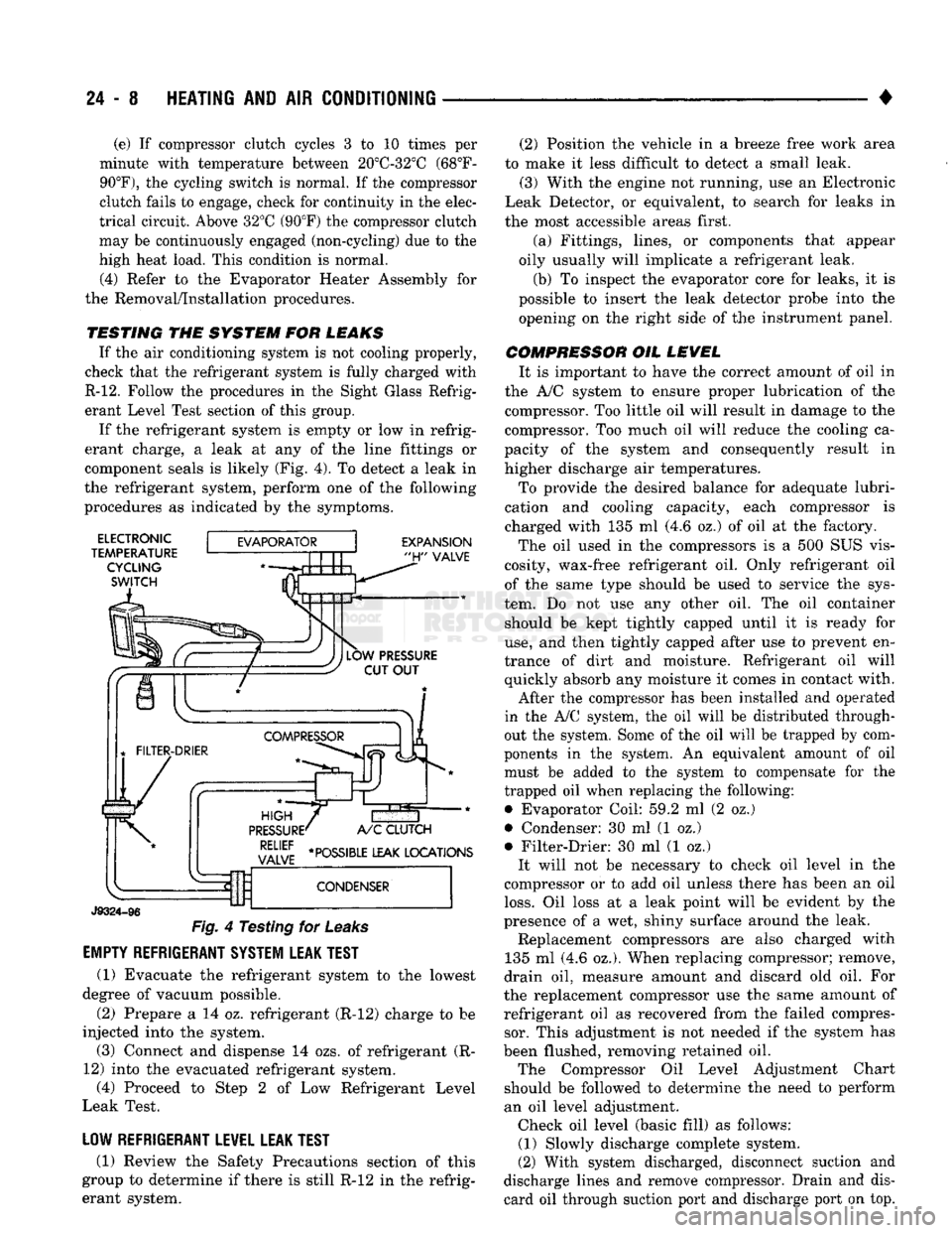
component seals is likely (Fig. 4). To detect a leak in
the refrigerant system, perform one of the following
procedures as indicated by the symptoms.
ELECTRONIC
TEMPERATURE CYCLING
SWITCH
EXPANSION
"H"
VALVE
J9324-96
Fig.
4 Testing for
Leaks
EMPTY REFRIGERANT SYSTEM LEAK TEST
(1) Evacuate the refrigerant system to the lowest
degree of vacuum possible.
(2) Prepare a 14 oz. refrigerant (R-12) charge to be
injected into the system. (3) Connect and dispense 14 ozs. of refrigerant (R-
12) into the evacuated refrigerant system, (4) Proceed to Step 2 of Low Refrigerant Level
Leak Test.
LOW REFRIGERANT LEVEL LEAK TEST
(1) Review the Safety Precautions section of this
group to determine if there is still R-12 in the refrig
erant system. (2) Position the vehicle in a breeze free work area
to make it less difficult to detect a small leak. (3) With the engine not running, use an Electronic
Leak Detector, or equivalent, to search for leaks in
the most accessible areas first.
(a) Fittings, lines, or components that appear
oily usually will implicate a refrigerant leak.
(b) To inspect the evaporator core for leaks, it is
possible to insert the leak detector probe into the opening on the right side of the instrument panel.
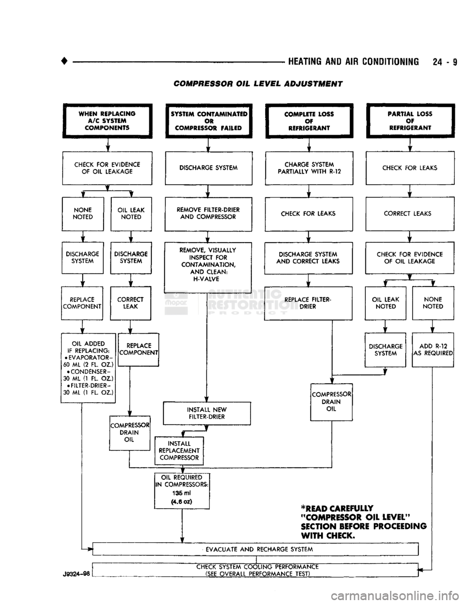
COMPRESSOR OIL LEVEL It is important to have the correct amount of oil in
the A/C system to ensure proper lubrication of the compressor. Too little oil will result in damage to the
compressor. Too much oil will reduce the cooling ca
pacity of the system and consequently result in
higher discharge air temperatures.
To provide the desired balance for adequate lubri
cation and cooling capacity, each compressor is
charged with 135 ml (4.6 oz.) of oil at the factory.
The oil used in the compressors is a 500 SUS vis
cosity, wax-free refrigerant oil. Only refrigerant oil of the same type should be used to service the sys
tem. Do not use any other oil. The oil container should be kept tightly capped until it is ready for
use,
and then tightly capped after use to prevent en
trance of dirt and moisture. Refrigerant oil will quickly absorb any moisture it comes in contact with.
After the compressor has been installed and operated
in the A/C system, the oil will be distributed through
out the system. Some of the oil will be trapped by com
ponents in the system. An equivalent amount of oil
must be added to the system to compensate for the
trapped oil when replacing the following: • Evaporator Coil: 59.2 ml (2 oz.)
• Condenser: 30 ml (1 oz.)
• Filter-Drier: 30 ml (1 oz.) It will not be necessary to check oil level in the
compressor or to add oil unless there has been an oil
loss.
Oil loss at a leak point will be evident by the
presence of a wet, shiny surface around the leak. Replacement compressors are also charged with
135 ml (4.6 oz.). When replacing compressor; remove,
drain oil, measure amount and discard old oil. For
the replacement compressor use the same amount of refrigerant oil as recovered from the failed compressor. This adjustment is not needed if the system has
been flushed, removing retained oil. The Compressor Oil Level Adjustment Chart
should be followed to determine the need to perform
an oil level adjustment. Check oil level (basic fill) as follows: (1) Slowly discharge complete system.
(2) With system discharged, disconnect suction and
discharge lines and remove compressor. Drain and dis card oil through suction port and discharge port on top.
Page 1446 of 1502
•
HEATING AND AIR CONDITIONING 24 - 9 COMPRESSOR OIL LEVEL ADJUSTMENT
WHEN
REPLACING
I
A/C SYSTEM
I
COMPONENTS
1
CHECK
FOR
EVIDENCE
OF
OIL
LEAKAGE
1
SYSTEM
COI
I
c
I COMPRESS
OTAMINATEI^
m 1
Ot FAILED
1
1
f
DISCHARGE SYSTEM
I
COMPLE
1
c
I
REFRIG TE LOSS
I
f 1
ERANT
1
i f
CHARGE SYSTEM
PARTIALLY
WITH
R-12 1
PARTIA
1
c
•
REFRIG L LOSS
1
)¥ I
ERANT
1
f
CHECK
FOR
LEAKS
NONE
NOTED
OIL LEAK
NOTED
r
DISCHARGE
SYSTEM
DISCHARGE
SYSTEM
r ] r
REPLACE
COMPONENT CORRECT
LEAK
OIL ADDED
IF REPLACING:
•
EVAPORATOR-
60 ML (2 FL. OZ.)
•
CONDENSER-
30 ML (1 FL. OZ.) •
FILTER-DRIER-
30 ML (1 FL. OZ.)
REPLACE
COMPONENT
COMPRESSOR
DRAIN OIL REMOVE FILTER-DRIER
AND COMPRESSOR CHECK
FOR
LEAKS
REMOVE, VISUALLY
INSPECT
FOR
CONTAMINATION,
AND CLEAN:
H-VALVE
1
1
DISCHARGE SYSTEM
AND CORRECT LEAKS
1
f
REPLACE
FILTER-
DRIER
INSTALL
NEW
FILTER-DRIER
COMPRESSOR
DRAIN OIL
INSTALL
REPLACEMENT
COMPRESSOR
OIL REQUIRED
IN COMPRESSORS: 136 ml
(4.6
oz) CORRECT LEAKS
CHECK
FOR
EVIDENCE OF
OIL
LEAKAGE
OIL LEAK
NOTED
NONE
NOTED
DISCHARGE
SYSTEM ADD
R-12
AS
REQUIRED
*READ
CAREFULLY
"COMPRESSOR
OIL
LEVEL"
SECTION
BEFORE
PROCEEDING
WITH
CHECK.
EVACUATE
AND
RECHARGE SYSTEM
J9324-98
CHECK SYSTEM COOLING PERFORMANCE
(SEE
OVERALL PERFORMANCE
TEST)
Page 1447 of 1502
24 - 10
HEATING
AND AIR
CONDITIONING
•
(3) Add 50 ml (1.7 oz.) of clean refrigerant oil
through the suction port.
(4) Install compressor.
(5) Install the suction and discharge lines to the
compressor. Use new gaskets to prevent leakage.
Tighten the line nuts to 23 N*m (200 in. lbs.) torque.
(6)
Evacuate and charge system.
OVER-ALL
PERFORMANCE
TEST
Humidity has an important bearing on the temper
ature of the air delivered to the vehicle's interior.
This is true of all air conditioning systems It is im
portant to understand the effect humidity has on the
performance of the system. When humidity is high,
the evaporator has to perform a double duty. It must lower the air temperature and the temperature of the
moisture carried in the air. Condensing the moisture
in the air transfers a great deal of heat energy into
the evaporator fins and tubing. This reduces the amount of heat the evaporator can absorb from the
air.
Evaporator capacity used to reduce the amount of
moisture in the air is not wasted. Wringing some of
the moisture out of the air entering the vehicle adds
to the comfort of the passengers. However, an owner may expect too much from their air conditioning sys
tem on humid days. A performance test is the best
way to determine whether or not the system is per
forming up to standard. This test also provides valu able clues to the possible cause of trouble.
To perform the test the air temperature in the test
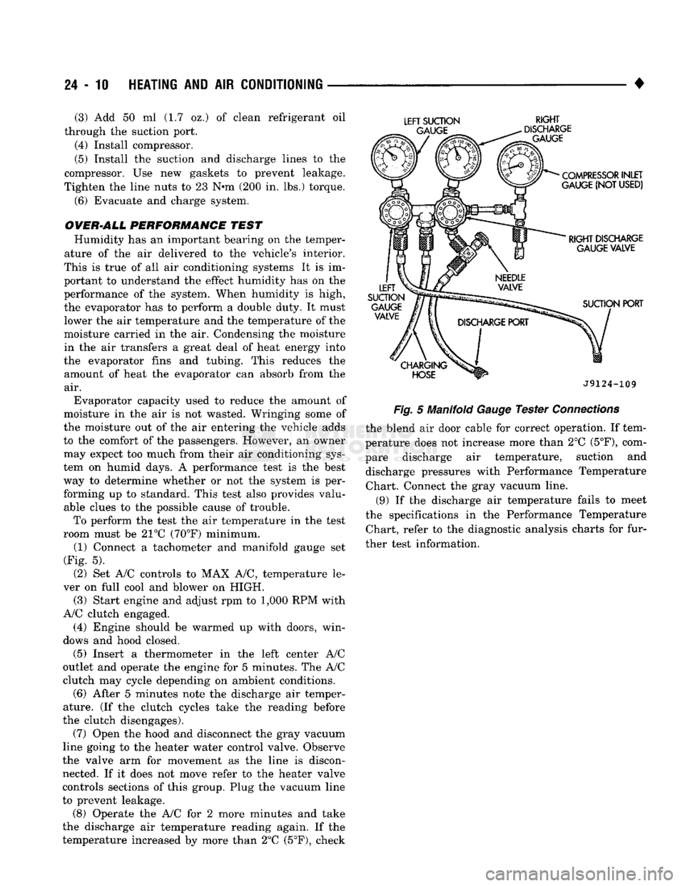
room must be 21°C (70°F) minimum. (1) Connect a tachometer and manifold gauge set
(Fig. 5).
(2) Set A/C controls to MAX A/C, temperature le
ver on full cool and blower on HIGH. (3) Start engine and adjust rpm to 1,000 RPM with
A/C clutch engaged.
(4) Engine should be warmed up with doors, win
dows and hood closed.
(5)
Insert a thermometer in the left center A/C
outlet and operate the engine for 5 minutes. The A/C
clutch may cycle depending on ambient conditions.
(6)
After 5 minutes note the discharge air temper
ature. (If the clutch cycles take the reading before
the clutch disengages).
(7) Open the hood and disconnect the gray vacuum
line going to the heater water control valve. Observe
the valve arm for movement as the line is discon nected. If it does not move refer to the heater valve
controls sections of this group. Plug the vacuum line
to prevent leakage.
(8) Operate the A/C for 2 more minutes and take
the discharge air temperature reading again. If the
temperature increased by more than 2°C (5°F), check
LEFT
SUCTION
RIGHT
J9124-109
Fig.
5 Manifold
Gauge
Tester
Connections
the blend air door cable for correct operation. If tem
perature does not increase more than 2°C
(5°F),
com
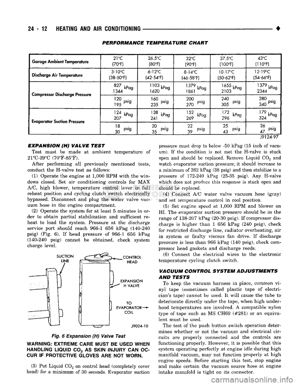
pare discharge air temperature, suction and discharge pressures with Performance Temperature Chart. Connect the gray vacuum line.
(9) If the discharge air temperature fails to meet
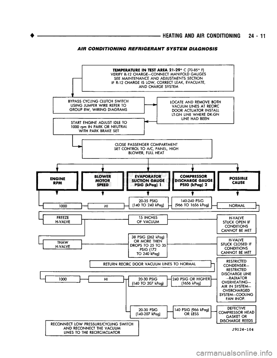
the specifications in the Performance Temperature Chart, refer to the diagnostic analysis charts for fur
ther test information.
Page 1448 of 1502
HEATING
AND
AIR
CONDITIONING
24 -
TEMPERATURE
IN
TEST AREA
21-29° C
(70-85°
F)
VERIFY R-12 CHARGE-CONNECT MANIFOLD GAUGES
SEE
MAINTENANCE AND ADJUSTMENTS SECTION
IF
R-12
CHARGE
IS
LOW, CORRECT LEAK, EVACUATE, AND CHARGE SYSTEM
BYPASS
CYCLING CLUTCH SWITCH USING JUMPER WIRE REFER
TO
GROUP
8W,
WIRING DIAGRAMS
START ENGINE ADJUST IDLE
TO 1000
rpm
IN
PARK OR NEUTRAL
WITH
PARK BRAKE SET LOCATE AND REMOVE BOTH
VACUUM LINES AT RECIRC DOOR ACTUATOR INSTALL
LT-GN LINE WHERE DK-GN LINE HAD BEEN
CLOSE
PASSENGER COMPARTMENT
SET
CONTROL TO A/C, PANEL, HIGH BLOWER, FULL HEAT
ENGINE
RPM BLOWER
MOTOR
SPEED
I
EVAPORATOR
I
SUCTION GAUGE
I
PSIG
(kPag)
1
COMPRESSOR
DISCHARGE
GAUGE
PSIG
(kPag)
2
—m
POSSIBLE
I
CAUSE
I
20-35
PSIG
140-240
PSIG
1000 —
HI
(140 TO 240
kPag)
(966
TO
1656
kPag)
i
— NORMAL
Cr a
FREEZE
H-VALVE 15 INCHES
OF VACUUM
THAW
H-VALVE 38 PSIG
(262
kPag)
OR MORE THEN
DROPS
TO 25 TO 35
PSIG
(172
TO
240
kPag)
RETURN RECIRC DOOR VACUUM LINES
TO
NORMAL a
1000
HI
20 30
PSIG
(140 TO 207
kPag)
H240
PSIG OR HIGHER
(1656
kPag)
20-30
PSIG
(140-207
kPag)
140
PSIG
(966
kPag)
OR
LESS
H-VALVE
STUCK OPEN
IF
CONDITIONS
CANNOT BE MET
H-VALVE
STUCK CLOSED
IF
CONDITIONS
CANNOT BE MET
RESTRICTED
CONDENSER-
RESTRICTED
DISCHARGE
LINE
-RADIATOR
OVERHEATING-
AIR
IN
SYSTEM- OVERCHARGED
SYSTEM-COOLING FAN INOP.
RECONNECT LOW PRESSURE/CYCLING SWITCH AND RECONNECT THE VACUUM LINES
TO
THE RECIRC/ACUATOR DEFECTIVE
COMPRESSOR
HEAD
GASKET
OR
DISCHARGE
REEDS
J9124-104
AIR
CONDITIONING REFRIGERANT SYSTEM DIAGNOSIS
Page 1449 of 1502
24-12
HEATING
AND AIR
CONDITIONING
PERFORMANCE TEMPERATURE CHART
Garage
Ambient
Temperature
21
°C
(70°F) 26.5°C
(80°F) 32°C
(90°F) 3/.5°'J
(100T) 43°C
(110°F)
Discharge
Air Temperature
3-10°C
(38-50°F) 6-12°C
(42-54'F) 8-14°C
(46-58°F) 10-17°C
(50-62°F) 12-19°C
(54-66°F)
Compressor
Discharge Pressure
1344 a
1620 a
1861 kPag 2103 a 1379kPcg
2344 a
Compressor
Discharge Pressure
120 •
195 PS'9 160 .
235 PS'9 200 .
270 PS'9 240 .
305 PS'9 280 .
340 PS'9
Evaporator
Suction Pressure
124 kPag
207 a 138 kPag
241 J 269 kPag III kP°9
296 179 ,D
324 kPag
Evaporator
Suction Pressure
18 .
30 PS'9 20 .
35 pS'g 22
39 pS,g
25 .
43 pS'g 26 .
47 pS'9
J9124-97 pressure must drop to below -50 kPag (15 inch of vacu
um).
If the condition is not met the H-valve is stuck
open and should be replaced. Remove Liquid C02 and
watch evaporator suction pressure; it should increase to a minimum of 262 kPag (38 psig) and then stabilize to a
pressure of 172-240 kPag (25-35 psig). Any H-valve
which does not produce this response is stuck open and should be replaced.
(4) Connect A/C water valve vacuum hose (gray)
and set temperature control in cool position.
(5) Set engine speed at 1,000 RPM and blower on
HI.
The evaporator suction pressure should be in the
range of 138-207 kPag (20-30 psig). If compressor dis charge is higher than 1 656 kPag (240 psig), check
for restricted discharge line, radiator overheating, air in system or faulty viscous fan drive. If discharge
pressure is less than 966 kPag (140 psig), check com
pressor head gaskets and discharge reeds.
(6) Connect the electrical wires to the electronic
temperature cycling clutch switch.
VACUUM CONTROL SYSTEM ADJUSTMENTS
AND TESTS To keep the vacuum harness in place, common vi
nyl tape (sometimes called plastic tape of electri
cian's tape) cannot be used. It will cause the tube to
deteriorate directly under the tape, when high under
hood temperatures are involved. A compatible nylon type of tape such as MS CH69 (#281) or an equivalent must be used.
The test of the push button switch operation deter
mines whether or not the vacuum and electrical cir cuits are properly connected and the controls are
functioning properly. However, it is possible that this system operating perfectly at engine idle during high
manifold vacuum, may not function properly at high engine speeds. Before starting this test, stop engine and make certain the vacuum source hose at engine
intake manifold is tight on its connector.
EXPANSION (H) VALVE TEST
Test must be made at ambient temperature of
21°C-29°C (70°F-85°F).
After performing all previously mentioned tests,
conduct the H-valve test as follows:
(1) Operate the engine at 1,000 RPM with the win
dows closed. Set air conditioning controls for MAX
A/C,
high blower, temperature control lever in full
reheat position and cycling clutch switch electrically
bypassed. Disconnect and plug the water valve vac uum hose in the engine compartment. (2) Operate the system for at least 5 minutes in or
der to obtain partial stabilization and sufficient re
heat to load the system. Pressure at the discharge service port should reach 966-1 656 kPag (140-240
psig) (Fig. 6). If head pressure of 966-1 656 kPag (140-240 psig) cannot be obtained, check system
charge level.
Fig.
6
Expansion
(H)
Valve
Test
WARNING:
EXTREME
CARE
MUST
BE
USED
WHEN
HANDLING
LIQUID
C02 AS
SKIN
INJURY
CAN OC
CUR
IF
PROTECTIVE
GLOVES
ARE NOT
WORN.
(3) Put Liquid C02 on control head (completely cover
head) for a minimum of 30 seconds. Evaporator suction
Page 1450 of 1502
•
HEATING
AND AIR
CONDITIONING
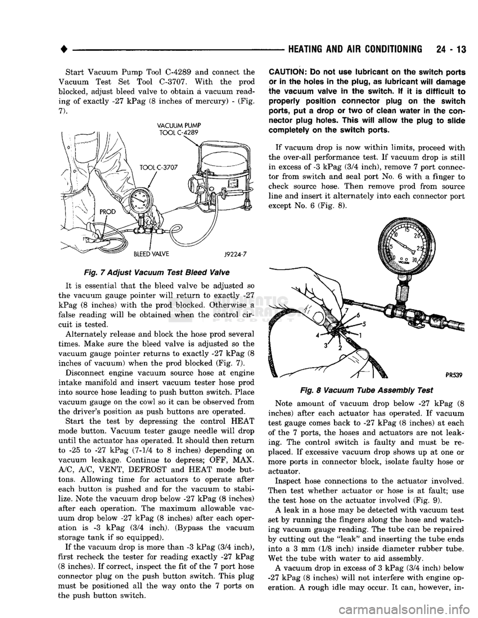
24 - 13 Start Vacuum Pump Tool
C-4289
and connect the
Vacuum Test Set Tool
C-3707.
With the prod
blocked, adjust bleed valve to obtain a vacuum read ing of exactly -27 kPag (8 inches of mercury) - (Fig.
7).
VACUUM PUMP
Fig.
7
Adjust
Vacuum
Test
Bleed
Valve
It is essential that the bleed valve be adjusted so
the vacuum gauge pointer will return to exactly -27 kPag (8 inches) with the prod blocked. Otherwise a
false reading will be obtained when the control cir
cuit is tested.
Alternately release and block the hose prod several
times.
Make sure the bleed valve is adjusted so the vacuum gauge pointer returns to exactly -27 kPag (8 inches of vacuum) when the prod blocked (Fig. 7).
Disconnect engine vacuum source hose at engine
intake manifold and insert vacuum tester hose prod
into source hose leading to push button switch. Place
vacuum gauge on the cowl so it can be observed from
the driver's position as push buttons are operated.
Start the test by depressing the control HEAT
mode button. Vacuum tester gauge needle will drop
until the actuator has operated. It should then return
to -25 to -27 kPag
(7-1/4
to 8 inches) depending on
vacuum leakage. Continue to depress; OFF, MAX.
A/C,
A/C,
VENT,
DEFROST
and
HEAT
mode but
tons.
Allowing time for actuators to operate after each button is pushed and for the vacuum to stabi
lize.
Note the vacuum drop below -27 kPag (8 inches)
after each operation. The maximum allowable vac
uum drop below -27 kPag (8 inches) after each oper ation is -3 kPag (3/4 inch). (Bypass the vacuum
storage tank if so equipped).
If the vacuum drop is more than -3 kPag (3/4 inch),
first recheck the tester for reading exactly -27 kPag
(8
inches). If correct, inspect the fit of the 7 port hose
connector plug on the push button switch. This plug
must be positioned all the way onto the 7 ports on
the push button switch.
CAUTION:
Do not use
lubricant
on the
switch ports
or
in the
holes
in the
plug,
as
lubricant
will
damage
the vacuum valve
in the
switch.
If it is
difficult
to
properly position connector plug
on the
switch
ports,
put a
drop
or two of
clean
water
in the
con
nector plug holes. This
will
allow
the
plug
to
slide
completely
on the
switch ports.
If vacuum drop is now within limits, proceed with
the over-all performance test. If vacuum drop is still in excess of
-3
kPag (3/4 inch), remove 7 port connec
tor from switch and seal port No. 6 with a finger to check source hose. Then remove prod from source
line and insert it alternately into each connector port
except No. 6 (Fig. 8).
Fig.
8
Vacuum
Tube
Assembly
Test
Note amount of vacuum drop below -27 kPag (8
inches) after each actuator has operated. If vacuum
test gauge comes back to -27 kPag (8 inches) at each of the 7 ports, the hoses and actuators are not leak
ing. The control switch is faulty and must be re
placed. If excessive vacuum drop shows up at one or
more ports in connector block, isolate faulty hose or actuator.
Inspect hose connections to the actuator involved.
Then test whether actuator or hose is at fault; use
the test hose on the actuator involved (Fig. 9).
A leak in a hose may be detected with vacuum test
set by running the fingers along the hose and watch
ing vacuum gauge reading. The tube can be repaired
by cutting out the "leak" and inserting the tube ends into a 3 mm (1/8 inch) inside diameter rubber tube.
Wet the tube with water to aid assembly.
A vacuum drop in excess of 3 kPag (3/4 inch) below
-27
kPag (8 inches) will not interfere with engine op
eration. A rough idle may occur. It can, however, in-