service DODGE TRUCK 1993 Service Manual PDF
[x] Cancel search | Manufacturer: DODGE, Model Year: 1993, Model line: TRUCK, Model: DODGE TRUCK 1993Pages: 1502, PDF Size: 80.97 MB
Page 237 of 1502
5
- 50
BRAKES
• Discard
the old
piston cups
and the
spring
and ex
pander. These parts
are not
reusable.
The
original
dust boots
may be
reused
but
only
if
they
are in
good condition.
ASSEMBLING
WHEEL
CYLINDER
(1) Lubricate wheel cylinder bore, pistons, piston
cups
and
spring
and
expander with clean brake fluid. (2) Install first piston
in
cylinder bore. Then
in
stall
cup in
bore
and
against piston.
Be
sure
lip of
piston
cup is
facing inward (toward spring
and
expander)
and
flat side
is
against piston.
(3) Install spring
and
expanders followed
by re
maining piston
cup and
piston.
(4) Install boots
on
each
end of
cylinder
and
insert
push rods
in
boots.
(5)
Install cylinder bleed screw.
WHEEL
CYLINDER INSTALLATION
(1) Apply bead
of
Mopar silicone sealer around cyl
inder mounting surface
of
support plate. (2) Connect brake line
to
cylinder. Mount cylinder
on support plate
and
install cylinder attaching bolts. (3) Install wheel brake components.
(4) Install brake drum
and
wheel
and
bleed
brakes.
DRUM
BRAKES—TWELVE INCH
INDEX
page
Brake Drum
Installation
54
Brake Drum Removal
52
Brake Drum Service
54
Brake
Shoe
Installation
53
Brakeshoe
Removal
52
Cleaning
and
Inspection
52
GENERAL
INFORMATION
Twelve inch rear drum brakes
are
used
on D and
W 250/350 models
(Fig. 1). All
applications
are
dual
shoe,
internal expanding units with
a
self adjusting
mechanism.
A
single wheel cylinder
is
used
to ex-
page
General
Information
50
Support
Plate
Installation
55
Support
Plate
Removal
55
Wheel
Cylinder
Installation
55
Wheel
Cylinder
Overhaul
...................
54
Wheel
Cylinder
Removal
. 54
pand
the
dual brakeshoes.
The
lower ends
of the
brake shoes
are
connected
by a
star wheel adjuster screw which
is
part
of the
self adjusting mechanism
(Fig.
1).
Page 241 of 1502
5
- 54
BRAKES
• (11) Attach adjuster cable to adjuster lever. Be
sure cable is properly routed.
(12) Adjust brakeshoes to drum with brake gauge.
BRAKE
DRUM INSTALLATION
(1) Position drum on axle housing.
(2) Install bearing and inner nut. Adjust bearing
as described in Group 3. (3) Install locking washer and outer nut. Bend
locking washer to secure it. (4) Place new gasket on hub and install axle shaft,
cones,
lock washers and nuts. (5) Install wheel and tire assembly.
(6) Remove support stands and lower vehicle.
BRAKE
DRUM
SERVICE
BRAKE DRUM REFINISHING The brake drums can be resurfaced on a drum
lathe when necessary. Initial machining cuts should
be limited to 0.12 - 0.20 mm (0.005 - 0.008 in.) at a time as heavier feed rates can produce taper and sur
face variation. Final finish cuts of 0.025 to 0.38 mm (0.001 to 0.0015 in) are recommended and will gen
erally provide the best surface finish.
Be sure the drum is securely mounted in the lathe
before machining operations. A damper strap should always be used around the drum to reduce vibration
and avoid chatter marks.
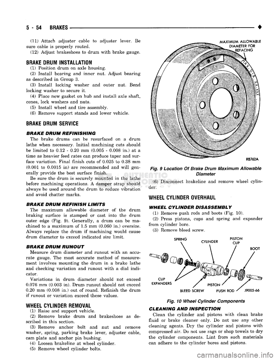
BRAKE DRUM REFINISH LIMITS The maximum allowable diameter of the drum
braking surface is stamped or cast into the drum outer edge (Fig. 9). Generally, a drum can be ma
chined to a maximum of 1.5 mm (0.060 in.) oversize.
Always replace the drum if machining would cause
drum diameter to exceed indicated size limit.
BRAKE DRUM RUNOUT Measure drum diameter and runout with an accu
rate gauge. The most accurate method of measure
ment involves mounting the drum in a brake lathe and checking variation and runout with a dial indi
cator.
Variations in drum diameter should not exceed
0.076 mm (0.003 in). Drum runout should not exceed
0.20 mm (0.008 in.) out of round. Refinish the drum
if runout or variation exceed these values.
WHEEL
CYLINDER REMOVAL
(1) Raise and support vehicle.
(2) Remove brake drum and brakeshoes as de
scribed in this section. (3) Remove anchor bolt and nut and remove
washer, spring, parking brake lever, adjuster cable, cam plate and anchor pin bushing. (4) Loosen brakeline at wheel cylinder.
(5) Remove wheel cylinder bolts. Fig. 9 Location Of Brake
Drum
Maximum Allowable
Diameter (6) Disconnect brakeline and remove wheel cylin
der.
WHEEL
CYLINDER OVERHAUL
WHEEL CYLINDER DISASSEMBLY (1) Remove push rods and boots (Fig. 10).
(2) Press pistons, cups and spring and expander
from cylinder bore. (3) Remove bleed screw.
Fig.
10
Wheel
Cylinder
Components
CLEANING AND INSPECTION Clean the cylinder and pistons with clean brake
fluid or brake cleaner only. Do not use any other cleaning agents. Dry the cylinder and pistons with
compressed air. Do not use rags or shop towels to dry
the cylinder components. Lint from such materials can adhere to the cylinder bores and pistons.
Page 246 of 1502
•
BRAKES
5 - 59
REAR
WHEEL
ANTILOCK
(RWAL) BRAKES
page
Antilock
Component Service
63
Antilock
Service Diagnosis
62
Checking
Speed
Sensor
Air
Gap .............
64
Clearing
A
Fault
Code .....................
63
Electronic
Control
Module Replacement
........
64
Fault Code Capacity
62
Fault Code
Identification
62
page
General
Information
59
Hydraulic Valve Replacement
63
Speed
Sensor
Replacement
................
64
System
Components
......................
59
System
Fault
Codes
......................
62
System
Operation
61
GENERAL
INFORMATION
A rear wheel antilock brake system
is
standard
equipment
on all AD
models.
It is an
electronically operated system designed
to
retard rear wheel lockup
during periods
of
high wheel slip
and
deceleration.
Retarding lockup
is
accomplished
by
modulating
fluid pressure
to the
rear brake units. Rear brake fluid apply pressure
is
modulated
ac
cording
to
wheel speed, degree
of
wheel slip
and
rate
of deceleration.
A
sensor located
in the
rear axle
housing converts differential rotating speed into elec
tronic signals.
The
signals
are
transmitted
to the
electronic brake control module
for
processing.
The
control unit determines rate
of
deceleration
and
wheel slip from these signals.
SYSTEM
COMPONENTS
Basic system components include
an
electronic
brake control module,
a
hydraulic pressure control
valve,
a
speed sensor
and
exciter ring
and an
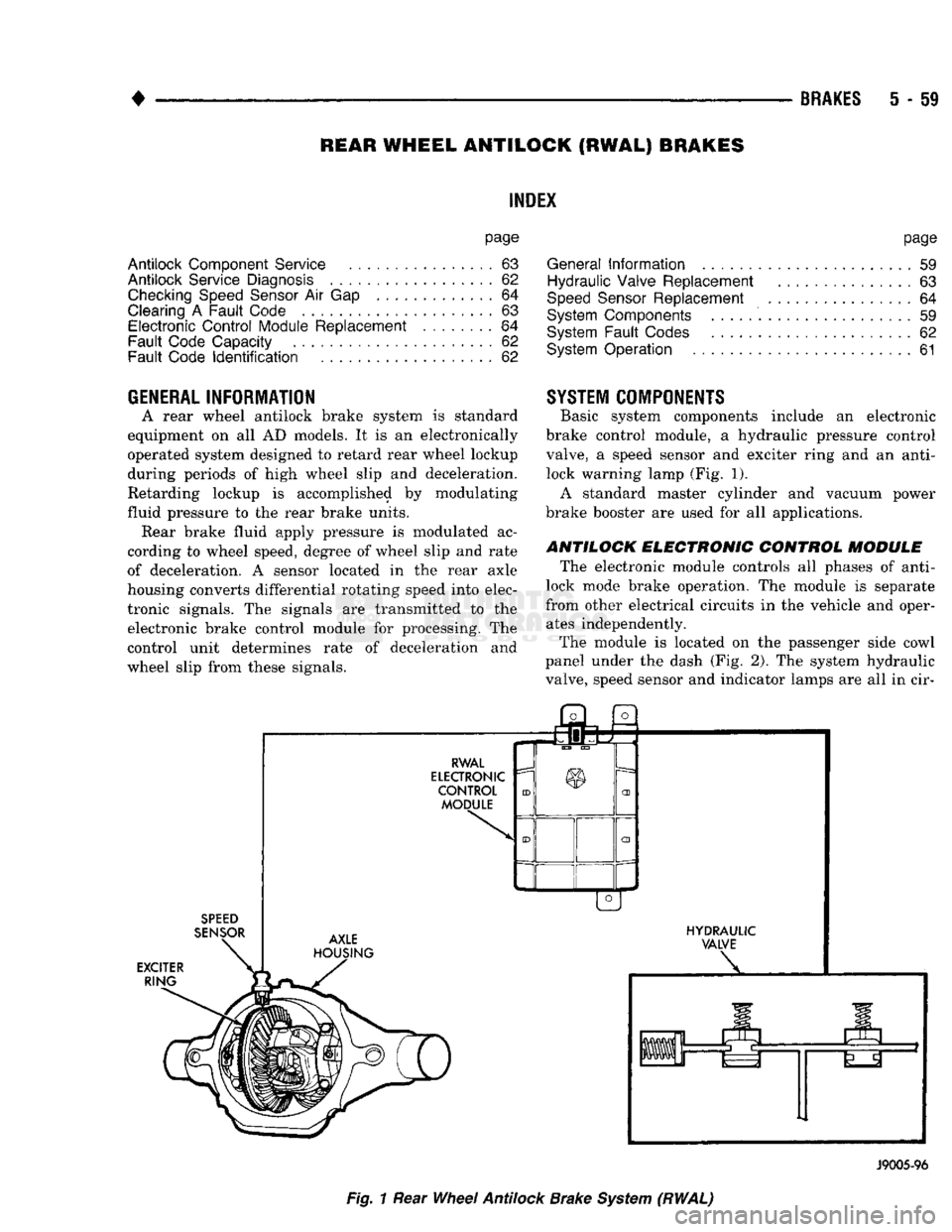
anti- lock warning lamp (Fig.
1).
A standard master cylinder
and
vacuum power
brake booster
are
used
for all
applications.
ANTILOCK ELECTRONIC CONTROL MODULE
The electronic module controls
all
phases
of
anti-
lock mode brake operation.
The
module
is
separate
from other electrical circuits
in the
vehicle
and
oper ates independently.
The module
is
located
on the
passenger side cowl
panel under
the
dash
(Fig.
2).
The
system hydraulic
valve, speed sensor
and
indicator lamps
are all in cir-
SPEED
SENSOR
EXCITER RING j3l
a
RWAL
ELECTRONIC
CONTROL MODULE AXLE
HOUSING HYDRAULIC
VALVE
J9005-96
Fig.
1
Rear
Wheel
Antilock
Brake
System
(RWAL)
Page 249 of 1502
i - 62
BRAKES
•
Isolation/Dump
Valve Cycle Times
Activation (opening/closing) of the isolation and
dump valves is continuous during antilock operation.
The valves cycle rapidly in response to speed sensor inputs and control module signal commands. Cycle
times are measured in milliseconds.
As the demand for antilock mode brake operation
is decreased, the module deactivates the hydraulic
valve components to restore normal brake operation.
ANTILOCK
SERVICE
DIAGNOSIS
GENERAL INFORMATION An antilock system malfunction will be indicated
by illumination of the amber antilock warning lamp.
The red brake warning lamp may also illuminate.
If a problem occurs, system diagnosis should begin
with a fluid level check followed by a visual exami
nation of the system electrical and hydraulic connec
tions.
If obvious defects (low fluid, leaks, loose connections, etc.) are not evident, road test the vehi
cle.
A road test should help determine if a malfunc
tion is actually related to an antilock component.
During the road test, note if other conditions are
evident such as a low pedal, pull, grab, or similar condition. Remember that brake malfunctions such as low fluid, system leaks, parking brakes partially
applied, will also affect the antilock system. The idea
is to determine if a malfunction is actually related to
an anti-lock component.
If a road test does reveal a problem, repeat the
road test with the owner driving. Make sure the owner is not riding the brake pedal, or has forgotten
to release the parking brakes. Either situation will
generate a fault and cause the antilock light to illu
minate.
SYSTEM FAULT
CODES
The antilock control module generates flash codes
to help identify the cause of an antilock system fault. Two different control modules are used with the
1992/1993 RWAL system. A type I module is used in
some early production models. All remaining produc
tion models are equipped with a type II module. The type I and II modules are identified by the way
fault codes 9 and 11 are processed. If the vehicle has a type I module, codes 9 and 11 are not erased when
the ignition switch is turned to Off position. If the vehicle has a type II module, codes 9 and 11 are
erased when the switch is turned to Off.
FAULT CODES WITH TYPE I CONTROL
MODULE
The microprocessor in the electronic control module
has a memory and a self test feature. The self test
feature is activated whenever the ignition switch is
turned to Accessory or Run position. If a system fault is detected, the control module il
luminates the antilock light and stores the fault code
in memory. Fault codes are retained in memory even after turning the ignition switch to Off position.
FAULT CODES WITH TYPE II CONTROL
MODULE The microprocessor in the electronic control module
has a memory and a self test feature. The self test
feature is activated whenever the ignition switch is
turned to Accessory or Run position.
If a system fault is detected, the control module
will illuminate the antilock indicator lamp and store
fault codes 1 through 8, 10 and 12 through 15 in the
microprocessor memory. When one of these fault
codes is generated, the control module will retain the code after the ignition switch is turned to the Off po
sition.
When fault code 9 is generated, the code only re
mains in microprocessor memory while the ignition switch is in Run position. Turning the ignition
switch to Off position erases fault code 9. However, if
the problem still exists when the switch is turned
back to Run position, code 9 will reappear in memory after 20 seconds and the antilock light will illumi
nate once again.
When fault code 11 is generated, the antilock light
will illuminate when vehicle speed exceeds approxi mately 60.35 km/h (37.5 mph). Code 11 only remains in memory while the ignition switch is in the Run
position and the fault is present.
When the cause of a fault code 11 is corrected, the
antilock light goes off. Code 11 is erased when the ig
nition switch is turned to Off position. However, if
the problem cause still exists when the ignition switch is turned to Run position, code 11 will reap
pear when vehicle speed exceeds approximately 60.35 km/h (37.5 mph).
FAULT
CODE
CAPACITY
The microprocessor memory will store and display
only one fault code at a time. The stored code can be
displayed by grounding the RWAL diagnostic connec
tor.
FAULT
CODE
IDENTIFICATION
To determine what the fault code is, momentarily
ground the RWAL diagnostic connector and count
the number of times the amber antilock lamp flashes. Fault codes and typical malfunctions are outlined in Figure 8. Note that when a fault code is gen
erated, the red brake warning lamp will also
illuminate. The initial flash will be a long flash followed by a
number of short flashes. The long flash indicates the
beginning of the fault number sequence and the short flashes are a continuation of that sequence.
Page 250 of 1502
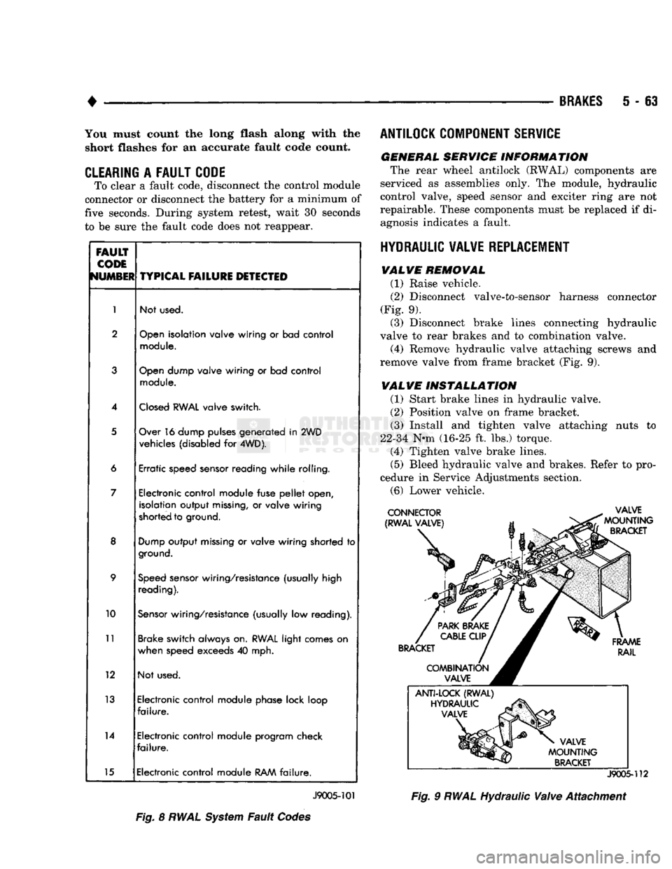
•
BRAKES
5 - 63 You must count the long flash along with the
short flashes for an accurate fault code count.
CLEARING
A
FAULT CODE
To clear a fault code, disconnect the control module
connector or disconnect the battery for a minimum of
five seconds. During system retest, wait 30 seconds
to be sure the fault code does not reappear.
FAULT
CODE
NUMBER
TYPICAL
FAILURE
DETECTED
1
Not used.
2
Open
isolation valve wiring
or
bad control
module.
3
Open
dump valve wiring
or
bad control
module.
4
Closed
RWAL
valve switch.
5
Over 16 dump pulses generated
in
2WD
vehicles (disabled
for
4WD).
6 Erratic speed sensor reading while rolling.
7 Electronic control module fuse
pellet
open,
isolation output
missing,
or
valve wiring
shorted to ground.
8
Dump
output
missing
or
valve wiring shorted
to
ground.
9
Speed
sensor wiring/resistance (usually high
reading).
10
Sensor
wiring/resistance (usually
low
reading).
11
Brake switch always on.
RWAL
light comes
on
when speed exceeds
40
mph.
12 Not used.
13 Electronic control module phase lock loop
failure.
14 Electronic control module program check
failure.
15 Electronic control module
RAM
failure.
J9005-101
Fig.
8
RWAL
System
Fault
Codes ANTILOCK COMPONENT SERVICE
GENERAL SERVICE INFORMATION
The rear wheel antilock (RWAL) components are
serviced as assemblies only. The module, hydraulic
control valve, speed sensor and exciter ring are not
repairable. These components must be replaced if di agnosis indicates a fault.
HYDRAULIC VALVE REPLACEMENT VALVE REMOVAL
(1) Raise vehicle.
(2)
Disconnect valve-to-sensor harness connector
(Fig. 9). (3) Disconnect brake lines connecting hydraulic
valve to rear brakes and to combination valve.
(4) Remove hydraulic valve attaching screws and
remove valve from frame bracket (Fig. 9).
VALVE INSTALLATION
(1) Start brake lines in hydraulic valve.
(2)
Position valve on frame bracket. (3) Install and tighten valve attaching nuts to
22-34 N-m (16-25 ft. lbs.) torque. (4) Tighten valve brake lines.
(5)
Bleed hydraulic valve and brakes. Refer to pro
cedure in Service Adjustments section.
(6)
Lower vehicle.
J9005-112
Fig.
9
RWAL
Hydraulic
Valve
Attachment
Page 254 of 1502
CLUTCH
6 - 1
CLUTCH
CONTENTS
page
CLUTCH
DIAGNOSIS
2
CLUTCH
COMPONENTS
MECHANICAL COMPONENTS
The clutch mechanism
in
AD
models with
a gas or
diesel engine consists
of a
single, dry-type clutch disc and
a
diaphragm style clutch cover.
A
hydraulic
linkage
is
used
to
engage/disengage
the
clutch disc
and cover.
The transmission input shaft
is
supported
in the
crankshaft
by a
bearing.
A
sleeve type release bear
ing
is
used
to
operate
the
clutch cover pressure plate.
The release bearing
is
operated
by a
release fork
in
the clutch housing.
The
fork pivots
on a
ball stud
mounted inside
the
housing.
The
release fork
is
actu ated
by a
hydraulic slave cylinder mounted
in the
housing.
The
slave cylinder
is
operated
by a
clutch master cylinder mounted
on the
dash panel.
The
cyl
inder push
rod is
connected
to the
clutch pedal.
The clutch disc
has
cushion springs
in the
disc
hub.
The clutch disc facing
is
riveted
to the hub. The
fac ing
is
made from
a
non-asbestos material.
The
clutch
cover pressure plate
is a
diaphragm type with
a one-
piece spring
and
multiple release fingers.
The
pres sure plate release fingers
are
preset during
manufacture
and are not
adjustable.
A
265 mm
clutch disc
and
cover
are
used
in
models
with
a 3.9L
engine.
A 280 mm
clutch disc
and
cover are used
in
models with
a 5.2L, or
5.9L engine.
A
330 mm
clutch disc
and
cover
are
used
in
models
equipped with
the
optional
5.9L
Cummins diesel
en
gine.
Some diesel models
are
also equipped with
a
clutch pedal interlock switch.
The
switch
is in
circuit
with
the
starter relay
and is
actuated
by the
clutch
pedal
and
push
rod. The
clutch pedal must
be
fully depressed
in
order
to
start
the
engine.
HYDRAULIC LINKAGE COMPONENTS
The hydraulic linkage consists
of a
remote reser
voir, clutch master cylinder, clutch slave cylinder and interconnecting fluid lines.
The clutch master cylinder
is
connected
to the
clutch pedal
and the
slave cylinder
is
connected
to
the clutch release fork.
The
master cylinder
is
mounted
on the
drivers' side
of the
dash panel adja
cent
to the
brake master cylinder.
page
CLUTCH
SERVICE
11
CLUTCH LINKAGE FLUID
The clutch fluid reservoir, master cylinder, slave
cylinder
and
fluid lines
are
prefilled with fluid
at the
factory during assembly operations. The hydraulic system should
not
require additional
fluid under normal circumstances.
In
fact,
the
reser
voir fluid level will actually increase
as
normal clutch wear occurs.
For
this reason,
it is
impor
tant
to
avoid overfilling,
or
removing fluid from
the reservoir. If inspection
or
diagnosis indicates additional fluid
may
be
needed,
use
Mopar brake fluid,
or an
equiv
alent meeting
SAE and DOT
standards J1703
and
DOT
3. Do not use any
other type
of
fluid.
CLUTCH
COMPONENT LUBRICATION
Proper clutch component lubrication
is
important
to satisfactory operation.
The
correct lubricant
and
not overlubricating
are
equally important. Apply rec
ommended lubricant sparingly
to
avoid disc
and
pres sure plate contamination. Clutch
and
transmission components requiring
lu
brication
are:
• pilot bearing
• release lever pivot ball stud
• release lever contact surfaces
• clutch disc
hub
splines
• clutch pedal pivot shaft bore
• clutch pedal bushings
• input shaft splines
• input shaft pilot
hub
• transmission front bearing retainer slide surface Do
not
apply grease
to any
part
of the
clutch
cover,
or
disc.
RECOMMENDED LUBRICANTS
Use Mopar multi-purpose grease
for the
clutch
pedal bushings
and
pivot shaft.
Use
Mopar high tem
perature grease
(or
equivalent)
for all
other lubrica
tion requirements. Apply recommended amounts
and
do
not
over lubricate.
Page 258 of 1502
•
CLUTCH
6 - 5
INDICATOR
PLUNGER
DIAL INDICATOR
CLUTCH
HOUSING
FACE
INDICATOR MOUNTING
„
STUD OR ROD
J9006-29
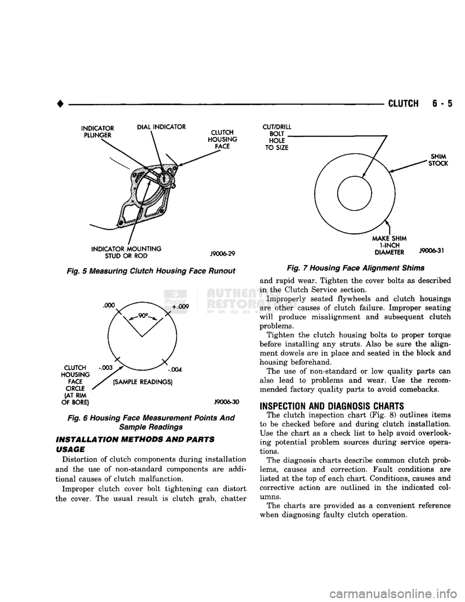
Fig.
5
Measuring
Clutch
Housing
Face
Runout
+
.009 CLUTCH
HOUSING
FACE
CIRCLE
(AT RIM
OF BORE)
,004
(SAMPLE
READINGS)
J9006-30
Fig.
6
Housing
Face Measurement
Points
And
Sample
Readings
INSTALLATION
METHODS
AND
PARTS
USAGE
Distortion of clutch components during installation
and the use of non-standard components are addi
tional causes of clutch malfunction.
Improper clutch cover bolt tightening can distort
the cover. The usual result is clutch grab, chatter
CUT/DRILL
BOLT
HOLE
TO SIZE SHIM
STOCK
MAKE
SHIM
1-INCH
DIAMETER
J9006-31
Fig.
7
Housing
Face
Alignment
Shims
and rapid wear. Tighten the cover bolts as described
in the Clutch Service section.
Improperly seated flywheels and clutch housings
are other causes of clutch failure. Improper seating
will produce misalignment and subsequent clutch problems.
Tighten the clutch housing bolts to proper torque
before installing any struts. Also be sure the align ment dowels are in place and seated in the block and
housing beforehand.
The use of non-standard or low quality parts can
also lead to problems and wear. Use the recom
mended factory quality parts to avoid comebacks.
INSPECTION AND DIAGNOSIS CHARTS
The clutch inspection chart (Fig. 8) outlines items
to be checked before and during clutch installation. Use the chart as a check list to help avoid overlooking potential problem sources during service opera
tions.
The diagnosis charts describe common clutch prob
lems,
causes and correction. Fault conditions are
listed at the top of each chart. Conditions, causes and
corrective action are outlined in the indicated col
umns.
The charts are provided as a convenient reference
when diagnosing faulty clutch operation.
Page 264 of 1502
•
CLUTCH
S - 11
CLUTCH
SERVICE
INDEX
page
Clutch
Cover
and
Disc
Installation—All
11
Clutch
Cover
and
Disc
Removal—All
. 11
Clutch
Housing
Installation
13
Clutch
Housing
Removal
12
Clutch
Linkage
Service
14
CLUTCH
COVER
AND
DISC
REMOVAL—ALL
(1) Raise vehicle.
(2) Remove transmission and remove transfer case
if equipped. Refer to Group 21 for procedures. (3) Remove clutch housing from engine.
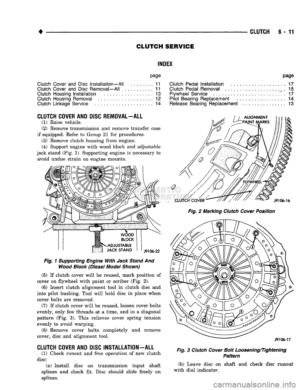
(4) Support engine with wood block and adjustable
jack stand (Fig. 1). Supporting engine is necessary to avoid undue strain on engine mounts.
Fig.
1
Supporting
Engine
With
Jack
Stand
And
Wood
Block
(Diesel
Model
Shown)
(5)
If clutch cover will be reused, mark position of
cover on flywheel with paint or scriber (Fig. 2).
(6)
Insert clutch alignment tool in clutch disc and
into pilot bushing. Tool will hold disc in place when
cover bolts are removed.
(7) If clutch cover will be reused, loosen cover bolts
evenly, only few threads at a time, and in a diagonal
pattern (Fig. 3). This relieves cover spring tension evenly to avoid warping.
(8) Remove cover bolts completely and remove
cover, disc and alignment tool.
CLUTCH
COVER
AND
DISC
INSTALLATION
-
ALL
(1) Check runout and free operation of new clutch
disc:
(a) Install disc on transmission input shaft
splines and check fit. Disc should slide freely on
splines.
page
Clutch
Pedal
Installation
17
Clutch
Pedal
Removal
. 15
Flywheel
Service
. 17
Pilot
Bearing
Replacement
14
Release
Bearing
Replacement
13
Fig.
2 Marking
Clutch
Cover
Position
J9106-17
Fig.
3
Clutch
Cover
Bolt
Loosening/Tightening
Pattern
(b) Leave disc on shaft and check disc runout
with dial indicator.
Page 267 of 1502
6
- 14
CLUTCH
(9) Install transmission. Also install transfer case
on 4-wheel drive models.
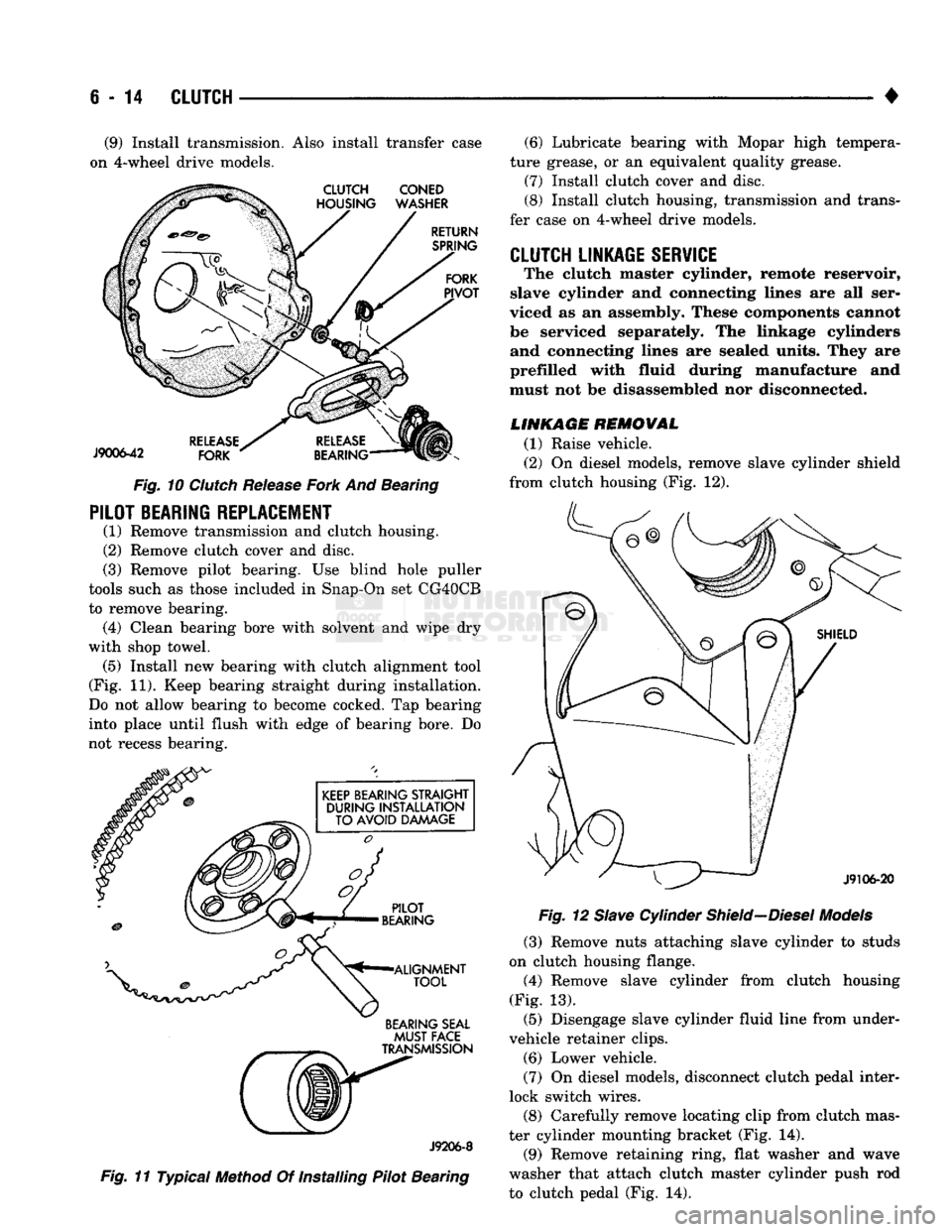
Fig.
10
Clutch
Release
Fork
And Bearing
PILOT BEARING REPLACEMENT
(1) Remove transmission and clutch housing.
(2) Remove clutch cover and disc.
(3) Remove pilot bearing. Use blind hole puller
tools such as those included in Snap-On set CG40CB
to remove bearing. (4) Clean bearing bore with solvent and wipe dry
with shop towel. (5) Install new bearing with clutch alignment tool
(Fig. 11). Keep bearing straight during installation.
Do not allow bearing to become cocked. Tap bearing
into place until flush with edge of bearing bore. Do
not recess bearing.
BEARING SEAL
MUST
FACE
J9206-8
Fig.
11 Typical Method Of Installing Pilot Bearing (6) Lubricate bearing with Mopar high tempera
ture grease, or an equivalent quality grease.
(7) Install clutch cover and disc.
(8) Install clutch housing, transmission and trans
fer case on 4-wheel drive models.
CLUTCH LINKAGE SERVICE
The clutch master cylinder, remote reservoir,
slave cylinder and connecting lines are all ser
viced as an assembly. These components cannot
be serviced separately. The linkage cylinders and connecting lines are sealed units. They are
prefilled with fluid during manufacture and
must not be disassembled nor disconnected.
LINKAGE REMOVAL
(1) Raise vehicle.
(2) On diesel models, remove slave cylinder shield
from clutch housing (Fig. 12).
Fig.
12
Slave
Cylinder
Shield—Diesel
Models
(3) Remove nuts attaching slave cylinder to studs
on clutch housing flange.
(4) Remove slave cylinder from clutch housing
(Fig. 13). (5) Disengage slave cylinder fluid line from under-
vehicle retainer clips. (6) Lower vehicle.
(7) On diesel models, disconnect clutch pedal inter
lock switch wires.
(8) Carefully remove locating clip from clutch mas
ter cylinder mounting bracket (Fig. 14). (9) Remove retaining ring, flat washer and wave
washer that attach clutch master cylinder push rod
to clutch pedal (Fig. 14).
Page 270 of 1502
•
CLUTCH
6-17
CLUTCH PEDAL INSTALLATION
(1) Lubricate pedal shaft, pedal shaft bore and all
bushings with Mopar Multi Mileage grease. (2) Insert pedal pin into cylinder push rod. Then
position clutch pedal in support. (3) Slide pedal shaft through clutch pedal bore and
bushings. (4) Install bolt that retains pedal shaft in support.
(5) Secure push rod to pedal pin with wave washer,
flat washer and retaining ring.
FLYWHEEL SERVICE
Inspect the flywheel whenever the clutch disc,
cover and housing are removed for service. Check
condition of the flywheel face, hub, ring gear teeth,
and flywheel bolts. Minor scratches, burrs, or glazing on the flywheel
face can be scuff sanded with 180 grit emery cloth. However, the flywheel should be replaced if the disc
contact surface is severely scored, heat checked,
cracked, or obviously worn. Cleanup of minor flywheel scoring should be per
formed with surface grinding equipment. Remove
only enough material to reduce scoring (approximate
ly 0.001 - 0.003 in.). Heavy stock removal is not rec
ommended. Replace the flywheel if scoring is severe
and deeper than 0.076 mm (0.003 in.). Excessive
stock removal can result in flywheel cracking or
warpage after installation; it can also weaken the flywheel and interfere with proper clutch release. Check flywheel runout if misalignment is sus
pected. Runout should not exceed 0.08 mm (0.003
in.).
Measure runout at the outer edge of the fly
wheel face with a dial indicator. Mount the dial in
dicator on a stud installed in place of one of the
flywheel attaching bolts. Clean the crankshaft flange before mounting the
flywheel. Dirt and grease on the flange surface may cock the flywheel causing excessive runout. Check condition of the flywheel hub and attaching
bolts.
Replace the flywheel if the hub exhibits cracks in the area of the attaching bolt holes. Install new attaching bolts whenever the flywheel
is replaced and use Mopar Lock N' Seal, or Loctite
242 on replacement bolt threads.
Recommended flywheel bolt torques are:
• 75 N»m (55 ft. lbs.) for gas engine flywheels
• 137 N*m (101 ft. lbs.) for diesel flywheels Inspect the teeth on the starter ring gear. If the
teeth are worn or damaged, the flywheel should
be replaced as an assembly. This is the recom mended and preferred method of repair.
In cases where a new flywheel is not readily avail
able,
a replacement ring gear can be installed. How
ever, the following precautions must be observed to
avoid damaging the flywheel and replacement gear.
(a) Mark position of the old gear for alignment
reference on the flywheel. Use a scriber for this
purpose.
(b) Wear protective goggles or approved safety
glasses. Also wear heat resistent gloves when han
dling a heated ring gear. (c) Remove the old gear by cutting most of the
way through it (at one point) with an abrasive cut off wheel. Then complete removal with a cold chisel
or punch. (d) The ring gear is a shrink fit on the flywheel.
This means the gear must be expanded by heating in order to install it. The method of heating and expanding the gear is extremely important. Ev
ery surface of the gear must be heated at the same
time to produce uniform expansion. An oven or
similar enclosed heating device must be used. Tem
perature required for uniform expansion is 325-350° F.
CAUTION:
Never
use an
oxy/acetylene torch
to re
move
the old
gear,
or to
heat
and
expand
a new
gear.
The
high temperature
of the
torch flame
will
cause
localized heating
and
damage
the
flywheel.
In
addition,
using
the
torch
to
heat
a
replacement gear
will
cause uneven heating
and
expansion.
The
torch
flame
will
also
anneal
the
gear
teeth
resulting
in
rapid wear
and
damage
after
installation.
(e) The heated gear must be installed evenly to
avoid misalignment or distortion. A shop press and
suitable press plates should be used to install the
gear if at all possible.
(f) Be sure to wear eye and hand protection.
Heat resistent gloves and safety goggles are needed
for personal safety. Also use metal tongs, vise
grips,
or similar tools to position the gear as necessary for installation.
(g) Allow the flywheel and ring gear to cool
down before installation. Set the assembly on a
workbench and let it cool in normal shop air.
CAUTION:
Do not
use water,
or
compressed
air to
cool
the
flywheel.
The
rapid cooling produced
by
water
or
compressed
air can
distort,
or
crack
the
gear
and
flywheel.