FIAT DUCATO 2006 Owner handbook (in English)
Manufacturer: FIAT, Model Year: 2006, Model line: DUCATO, Model: FIAT DUCATO 2006Pages: 238, PDF Size: 3.29 MB
Page 11 of 238
10
SAFETY
DEVICES
CORRECT USE
OF THE
VEHICLE
WARNING
LIGHTS AND
MESSAGES
IN AN
EMERGENCY
VEHICLE
MAINTENANCE
TECHNICAL
SPECIFICATIONS
INDEX
DASHBOARD
AND CONTROLS
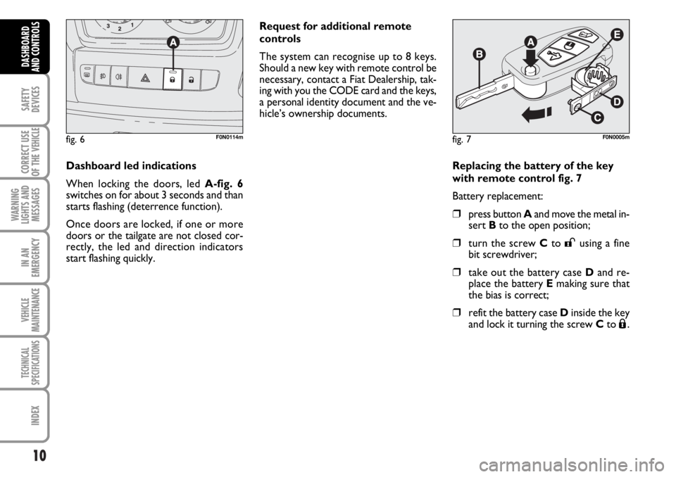
Replacing the battery of the key
with remote control fig. 7
Battery replacement:
❒press button Aand move the metal in-
sert Bto the open position;
❒turn the screw Cto :using a fine
bit screwdriver;
❒take out the battery case Dand re-
place the battery Emaking sure that
the bias is correct;
❒refit the battery case Dinside the key
and lock it turning the screw Cto Á.
fig. 7F0N0005m
Request for additional remote
controls
The system can recognise up to 8 keys.
Should a new key with remote control be
necessary, contact a Fiat Dealership, tak-
ing with you the CODE card and the keys,
a personal identity document and the ve-
hicle’s ownership documents.
Dashboard led indications
When locking the doors, led A-fig. 6
switches on for about 3 seconds and than
starts flashing (deterrence function).
Once doors are locked, if one or more
doors or the tailgate are not closed cor-
rectly, the led and direction indicators
start flashing quickly.
fig. 6F0N0114m
Page 12 of 238
11
SAFETY
DEVICES
CORRECT USE
OF THE
VEHICLE
WARNING
LIGHTS AND
MESSAGES
IN AN
EMERGENCY
VEHICLE
MAINTENANCE
TECHNICAL
SPECIFICATIONS
INDEX
DASHBOARD
AND CONTROLS
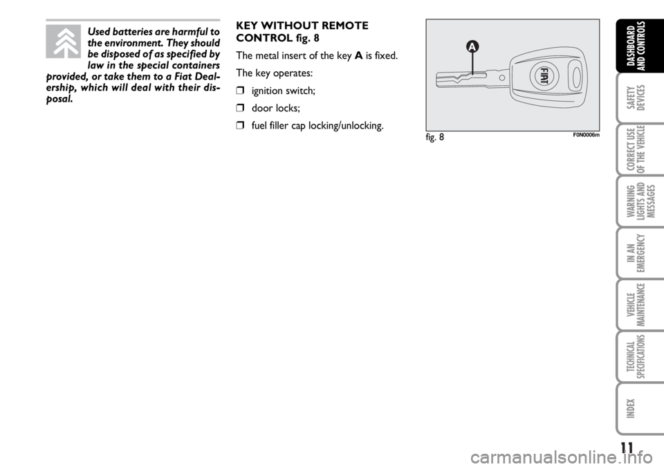
KEY WITHOUT REMOTE
CONTROL fig. 8
The metal insert of the key Ais fixed.
The key operates:
❒ignition switch;
❒door locks;
❒fuel filler cap locking/unlocking.fig. 8F0N0006m
Used batteries are harmful to
the environment. They should
be disposed of as specified by
law in the special containers
provided, or take them to a Fiat Deal-
ership, which will deal with their dis-
posal.
Page 13 of 238
Type of key
Key without
remote control
Key with remote control
Direction
indicators flashing
(only with key with
remote control)
Deterrence led
12
SAFETY
DEVICES
CORRECT USE
OF THE
VEHICLE
WARNING
LIGHTS AND
MESSAGES
IN AN
EMERGENCY
VEHICLE
MAINTENANCE
TECHNICAL
SPECIFICATIONS
INDEX
DASHBOARD
AND CONTROLS
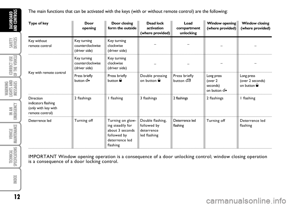
The main functions that can be activated with the keys (with or without remote control) are the following:
Door
opening
Key turning
counterclockwise
(driver side)
Key turning
counterclockwise
(driver side)
Press briefly
button
Æ
2 flashings
Turning offDoor closing
form the outside
Key turning
clockwise
(driver side)
Key turning
clockwise
(driver side)
Press briefly
button Ø
1 flashing
Turning on glow-
ing steadily for
about 3 seconds
followed by
deterrence led
flashingDead lock
activation
(where provided)
–
–
Double pressing
on button Ø
3 flashings
Double flashing,
followed by
deterrence
led flashingLoad
compartment
unlocking
–
–
Press briefly
button ∞
2 flashings
Deterrence led
flashing
IMPORTANT Window opening operation is a consequence of a door unlocking control; window closing operation
is a consequence of a door locking control.
Window closing
(where provided)
–
–
Long press(over 2 seconds)
on button Ø
1 flashing
Deterrence led
flashing Window opening
(where provided)
–
–
Long press(over 2
seconds)
on button
Æ
2 flashings
Turning off
Page 14 of 238
13
SAFETY
DEVICES
CORRECT USE
OF THE
VEHICLE
WARNING
LIGHTS AND
MESSAGES
IN AN
EMERGENCY
VEHICLE
MAINTENANCE
TECHNICAL
SPECIFICATIONS
INDEX
DASHBOARD
AND CONTROLS
IGNITION
DEVICE
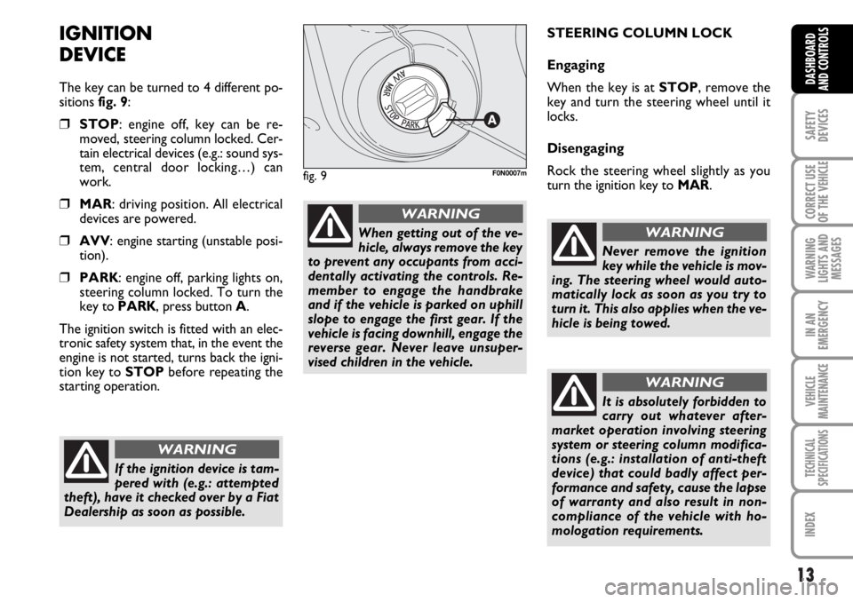
The key can be turned to 4 different po-
sitions fig. 9:
❒STOP: engine off, key can be re-
moved, steering column locked. Cer-
tain electrical devices (e.g.: sound sys-
tem, central door locking…) can
work.
❒MAR: driving position. All electrical
devices are powered.
❒AVV: engine starting (unstable posi-
tion).
❒PARK: engine off, parking lights on,
steering column locked. To turn the
key to PARK, press button A.
The ignition switch is fitted with an elec-
tronic safety system that, in the event the
engine is not started, turns back the igni-
tion key to STOPbefore repeating the
starting operation.STEERING COLUMN LOCK
Engaging
When the key is at STOP, remove the
key and turn the steering wheel until it
locks.
Disengaging
Rock the steering wheel slightly as you
turn the ignition key to MAR.
If the ignition device is tam-
pered with (e.g.: attempted
theft), have it checked over by a Fiat
Dealership as soon as possible.
WARNING
When getting out of the ve-
hicle, always remove the key
to prevent any occupants from acci-
dentally activating the controls. Re-
member to engage the handbrake
and if the vehicle is parked on uphill
slope to engage the first gear. If the
vehicle is facing downhill, engage the
reverse gear. Never leave unsuper-
vised children in the vehicle.
WARNING
fig. 9F0N0007m
Never remove the ignition
key while the vehicle is mov-
ing. The steering wheel would auto-
matically lock as soon as you try to
turn it. This also applies when the ve-
hicle is being towed.
WARNING
It is absolutely forbidden to
carry out whatever after-
market operation involving steering
system or steering column modifica-
tions (e.g.: installation of anti-theft
device) that could badly affect per-
formance and safety, cause the lapse
of warranty and also result in non-
compliance of the vehicle with ho-
mologation requirements.
WARNING
Page 15 of 238
14
SAFETY
DEVICES
CORRECT USE
OF THE
VEHICLE
WARNING
LIGHTS AND
MESSAGES
IN AN
EMERGENCY
VEHICLE
MAINTENANCE
TECHNICAL
SPECIFICATIONS
INDEX
DASHBOARD
AND CONTROLS
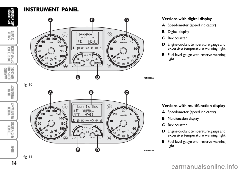
INSTRUMENT PANEL
Versions with digital display
ASpeedometer (speed indicator)
BDigital display
CRev counter
DEngine coolant temperature gauge and
excessive temperature warning light
EFuel level gauge with reserve warning
light
Versions with multifunction display
ASpeedometer (speed indicator)
BMultifunction display
CRev counter
DEngine coolant temperature gauge and
excessive temperature warning light
EFuel level gauge with reserve warning
light
F0N0008m
fig. 10
F0N0010m
fig. 11
Page 16 of 238
15
SAFETY
DEVICES
CORRECT USE
OF THE
VEHICLE
WARNING
LIGHTS AND
MESSAGES
IN AN
EMERGENCY
VEHICLE
MAINTENANCE
TECHNICAL
SPECIFICATIONS
INDEX
DASHBOARD
AND CONTROLS
INSTRUMENTS
Instrument background color and type
may vary according to the version.
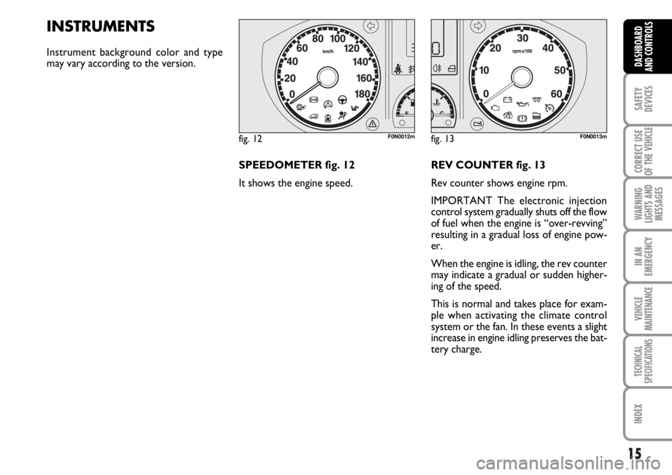
SPEEDOMETER fig. 12
It shows the engine speed.REV COUNTER fig. 13
Rev counter shows engine rpm.
IMPORTANT The electronic injection
control system gradually shuts off the flow
of fuel when the engine is “over-revving”
resulting in a gradual loss of engine pow-
er.
When the engine is idling, the rev counter
may indicate a gradual or sudden higher-
ing of the speed.
This is normal and takes place for exam-
ple when activating the climate control
system or the fan. In these events a slight
increase in engine idling preserves the bat-
tery charge.
fig. 12F0N0012mfig. 13F0N0013m
Page 17 of 238
16
SAFETY
DEVICES
CORRECT USE
OF THE
VEHICLE
WARNING
LIGHTS AND
MESSAGES
IN AN
EMERGENCY
VEHICLE
MAINTENANCE
TECHNICAL
SPECIFICATIONS
INDEX
DASHBOARD
AND CONTROLS
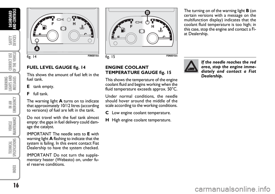
FUEL LEVEL GAUGE fig. 14
This shows the amount of fuel left in the
fuel tank.
Etank empty.
Ffull tank.
The warning light Aturns on to indicate
that approximately 10/12 litres (according
to versions) of fuel are left in the tank.
Do not travel with the fuel tank almost
empty: the gaps in fuel delivery could dam-
age the catalyst.
IMPORTANT The needle sets to Ewith
warning light Aflashing to indicate that the
system is failing. In this event contact Fiat
Dealership to have the system checked.
IMPORTANT Do not turn the supple-
mentary heater (Webasto) on, under fu-
el reserve conditions.ENGINE COOLANT
TEMPERATURE GAUGE fig. 15
This shows the temperature of the engine
coolant fluid and begins working when the
fluid temperature exceeds approx. 50°C.
Under normal conditions, the needle
should hover around the middle of the
scale according to the working conditions.
CLow engine coolant temperature.
HHigh engine coolant temperature.The turning on of the warning light B(on
certain versions with a message on the
multifunction display) indicates that the
coolant fluid temperature is too high; in
this case, stop the engine and contact a Fi-
at Dealership.
fig. 14F0N0014mfig. 15F0N0015m
If the needle reaches the red
area, stop the engine imme-
diately and contact a Fiat
Dealership.
Page 18 of 238
17
SAFETY
DEVICES
CORRECT USE
OF THE
VEHICLE
WARNING
LIGHTS AND
MESSAGES
IN AN
EMERGENCY
VEHICLE
MAINTENANCE
TECHNICAL
SPECIFICATIONS
INDEX
DASHBOARD
AND CONTROLS
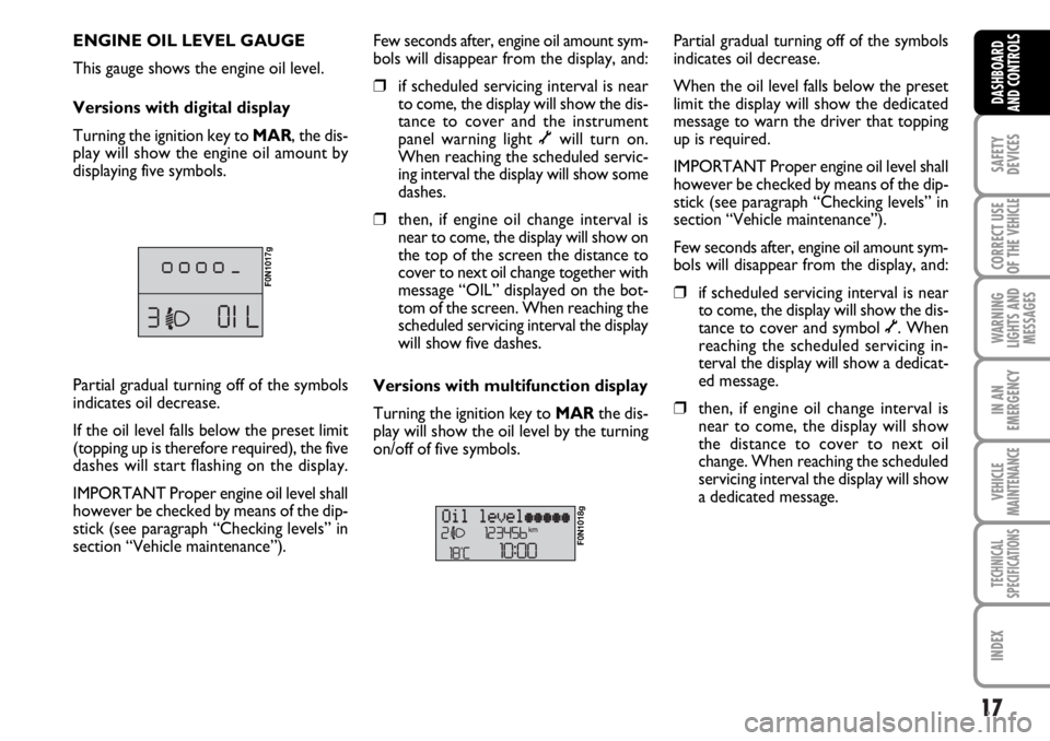
ENGINE OIL LEVEL GAUGE
This gauge shows the engine oil level.
Versions with digital display
Turning the ignition key to MAR, the dis-
play will show the engine oil amount by
displaying five symbols.
F0N1017g
Few seconds after, engine oil amount sym-
bols will disappear from the display, and:
❒if scheduled servicing interval is near
to come, the display will show the dis-
tance to cover and the instrument
panel warning light õwill turn on.
When reaching the scheduled servic-
ing interval the display will show some
dashes.
❒then, if engine oil change interval is
near to come, the display will show on
the top of the screen the distance to
cover to next oil change together with
message “OIL” displayed on the bot-
tom of the screen. When reaching the
scheduled servicing interval the display
will show five dashes.
Versions with multifunction display
Turning the ignition key to MARthe dis-
play will show the oil level by the turning
on/off of five symbols.
F0N1018g
Partial gradual turning off of the symbols
indicates oil decrease.
When the oil level falls below the preset
limit the display will show the dedicated
message to warn the driver that topping
up is required.
IMPORTANT Proper engine oil level shall
however be checked by means of the dip-
stick (see paragraph “Checking levels” in
section “Vehicle maintenance”).
Few seconds after, engine oil amount sym-
bols will disappear from the display, and:
❒if scheduled servicing interval is near
to come, the display will show the dis-
tance to cover and symbol õ. When
reaching the scheduled servicing in-
terval the display will show a dedicat-
ed message.
❒then, if engine oil change interval is
near to come, the display will show
the distance to cover to next oil
change. When reaching the scheduled
servicing interval the display will show
a dedicated message. Partial gradual turning off of the symbols
indicates oil decrease.
If the oil level falls below the preset limit
(topping up is therefore required), the five
dashes will start flashing on the display.
IMPORTANT Proper engine oil level shall
however be checked by means of the dip-
stick (see paragraph “Checking levels” in
section “Vehicle maintenance”).
Page 19 of 238
18
SAFETY
DEVICES
CORRECT USE
OF THE
VEHICLE
WARNING
LIGHTS AND
MESSAGES
IN AN
EMERGENCY
VEHICLE
MAINTENANCE
TECHNICAL
SPECIFICATIONS
INDEX
DASHBOARD
AND CONTROLS
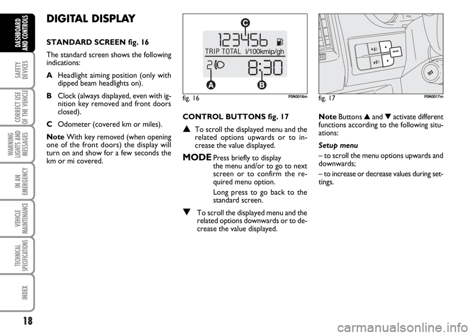
DIGITAL DISPLAY
STANDARD SCREEN fig. 16
The standard screen shows the following
indications:
AHeadlight aiming position (only with
dipped beam headlights on).
BClock (always displayed, even with ig-
nition key removed and front doors
closed).
COdometer (covered km or miles).
NoteWith key removed (when opening
one of the front doors) the display will
turn on and show for a few seconds the
km or mi covered.CONTROL BUTTONS fig. 17
▲To scroll the displayed menu and the
related options upwards or to in-
crease the value displayed.
MODEPress briefly to display
the menu and/or to go to next
screen or to confirm the re-
quired menu option.
Long press to go back to the
standard screen.
▼To scroll the displayed menu and the
related options downwards or to de-
crease the value displayed.NoteButtons ▲and ▼activate different
functions according to the following situ-
ations:
Setup menu
– to scroll the menu options upwards and
downwards;
– to increase or decrease values during set-
tings.
fig. 16F0N0016mfig. 17F0N0017m
Page 20 of 238

19
SAFETY
DEVICES
CORRECT USE
OF THE
VEHICLE
WARNING
LIGHTS AND
MESSAGES
IN AN
EMERGENCY
VEHICLE
MAINTENANCE
TECHNICAL
SPECIFICATIONS
INDEX
DASHBOARD
AND CONTROLS
SETUP MENU fig. 18
The menu comprises a series of functions
arranged in a “circular fashion” which can
be selected through buttons ▲and ▼to
access the different select operations and
settings (setup) given in the following para-
graphs.
The setup menu can be activated by press-
ing briefly button MODE.
Single presses on buttons ▲and ▼will
scroll the setup menu options.
Handling modes differ with each other ac-
cording to the characteristic of the option
selected.Selecting a menu option
– press briefly button MODEto select
the menu option to set;
– press buttons ▲and ▼(by single press-
es) to select the new setting;
– press briefly button MODEto store the
new setting and to go back to the previ-
ously selected menu option.
Selecting “Set Clock”
– briefly press button MODEto select
the first value to change (hours);
– press buttons ▲and ▼(by single press-
es) to select the new setting;
– briefly press button MODEto store the
new setting and to go to the next setup
menu option (minutes);
– after setting the values with the same
procedure, you’ll go back to the menu op-
tion previously selected.Press the button MODE for long
– to quit the set up menu if you are in the
menu;
– to quit the displayed menu if you are set-
ting an option;
– to save only the settings stored yet (and
confirmed by pressing button MODE).
The setup menu displaying is timed; when
quitting the menu due to timing expiry, on-
ly settings stored yet by the user (and con-
firmed by pressing briefly button MODE)
will be saved.