turn signal FIAT DUCATO 2006 Owner handbook (in English)
[x] Cancel search | Manufacturer: FIAT, Model Year: 2006, Model line: DUCATO, Model: FIAT DUCATO 2006Pages: 238, PDF Size: 3.29 MB
Page 63 of 238

62
SAFETY
DEVICES
CORRECT USE
OF THE
VEHICLE
WARNING
LIGHTS AND
MESSAGES
IN AN
EMERGENCY
VEHICLE
MAINTENANCE
TECHNICAL
SPECIFICATIONS
INDEX
DASHBOARD
AND CONTROLS
RAIN SENSOR
(where provided)
The rain sensor is located behind the dri-
ving mirror in contact with the windscreen
and has the purpose of automatically ad-
just, during the intermittent operation, the
frequency of the windscreen wiper
strokes as to the rain intensity.
IMPORTANT Keep clean the glass in the
sensor area.
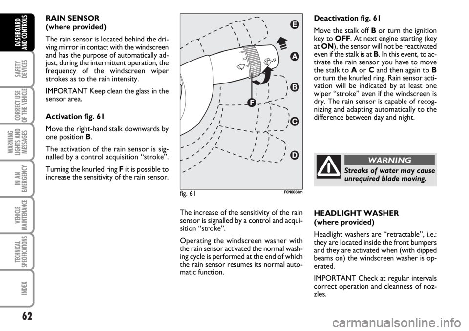
Activation fig. 61
Move the right-hand stalk downwards by
one position B.
The activation of the rain sensor is sig-
nalled by a control acquisition “stroke”.
Turning the knurled ring Fit is possible to
increase the sensitivity of the rain sensor.
The increase of the sensitivity of the rain
sensor is signalled by a control and acqui-
sition “stroke”.
Operating the windscreen washer with
the rain sensor activated the normal wash-
ing cycle is performed at the end of which
the rain sensor resumes its normal auto-
matic function.HEADLIGHT WASHER
(where provided)
Headlight washers are “retractable”, i.e.:
they are located inside the front bumpers
and they are activated when (with dipped
beams on) the windscreen washer is op-
erated.
IMPORTANT Check at regular intervals
correct operation and cleanness of noz-
zles. Deactivation fig. 61
Move the stalk off Bor turn the ignition
key to OFF. At next engine starting (key
at ON), the sensor will not be reactivated
even if the stalk is at B. In this event, to ac-
tivate the rain sensor you have to move
the stalk to Aor Cand then again to B
or turn the knurled ring. Rain sensor acti-
vation will be indicated by at least one
wiper “stroke” even if the windscreen is
dry. The rain sensor is capable of recog-
nizing and adapting automatically to the
difference between day and night.
fig. 61F0N0038m
Streaks of water may cause
unrequired blade moving.
WARNING
Page 86 of 238

85
SAFETY
DEVICES
CORRECT USE
OF THE
VEHICLE
WARNING
LIGHTS AND
MESSAGES
IN AN
EMERGENCY
VEHICLE
MAINTENANCE
TECHNICAL
SPECIFICATIONS
INDEX
DASHBOARD
AND CONTROLS
BRAKE ASSIST
(emergency braking assistance
integral with ESP) (where provided)
The system, which cannot be cut out, rec-
ognizes emergency braking (on the ground
of the brake pedal operation speed) and
considerably increases the pressure in the
brake circuit.
Brake Assist is deactivated on the versions
equipped with ESP, in the event of ESP sys-
tem failure (indicated by warning light
áswitching on together with the message
on the multifunction display, where pro-
vided).
ESP SYSTEM
(Electronic Stability
Program)
(where provided)
The ESP system is an electronic system
controlling the vehicle stability in the event
of tyre grip loss.
The ESP system is therefore particularly
useful when grip conditions of the road sur-
faces changes.
In addition to the ESP system, ASR system
and Hill Holder, (where provided) also the
MSR system (adjusting the engine braking
torque) and the HBA system (improving
the braking force during emergency brak-
ing) are provided.
ESP SYSTEM INTERVENTION
It is signalled by the blinking of the warn-
ing light áon the instrument panel, to in-
form the driver that the vehicle is in crit-
ical stability and grip conditions.
When the ABS cuts in, and
you feel the brake pedal pul-
sating, do not remove your foot, but
keep it pressed; in doing so you will
stop in the shortest amount of space
possible under the current road con-
ditions.
WARNING
EBD failure
EBD failure is indicated by the turning on
of warning lights
>and xon the in-
strument panel together with the dedi-
cated message on the multifunction dis-
play (where provided), (see section
“Warning lights and messages”).
In this case with sharp braking the rear
wheels might lock too early, with the pos-
sibility of skidding. Drive extremely care-
fully to the nearest Fiat Dealership to have
the system checked.
If warning light xalone
comes on (together with the
message on the multifunction display,
where provided), stop the vehicle im-
mediately and contact the nearest Fi-
at Dealership. Fluid leaks from the hy-
draulic system, in fact, can compro-
mise the braking system, both tradi-
tional systems and systems with ABS.
WARNING
Page 90 of 238

89
SAFETY
DEVICES
CORRECT USE
OF THE
VEHICLE
WARNING
LIGHTS AND
MESSAGES
IN AN
EMERGENCY
VEHICLE
MAINTENANCE
TECHNICAL
SPECIFICATIONS
INDEX
DASHBOARD
AND CONTROLS
PARKING SENSORS
(where provided)
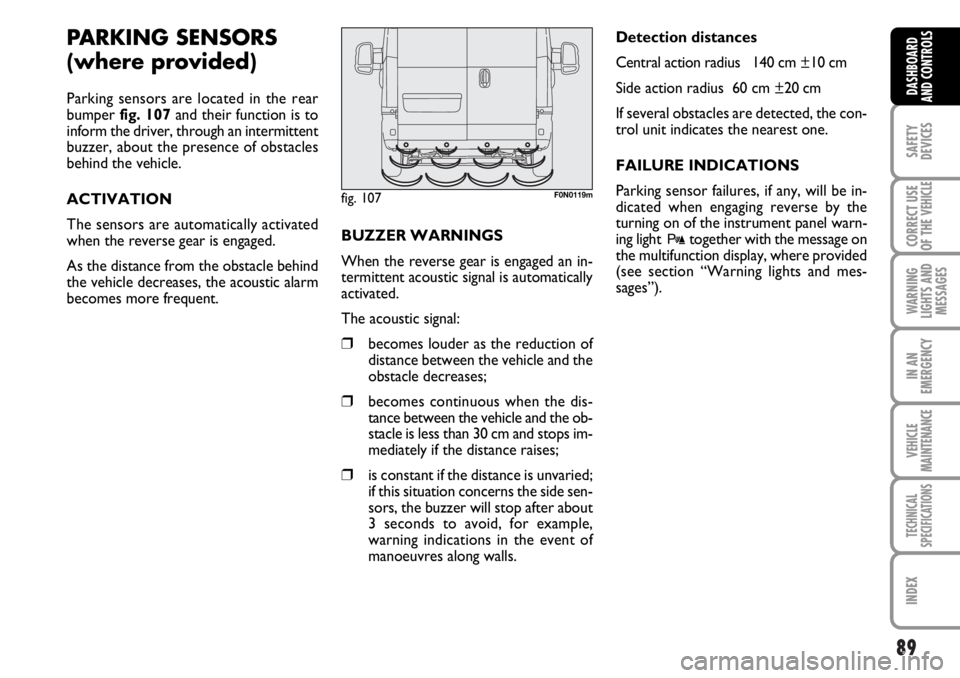
Parking sensors are located in the rear
bumper fig. 107and their function is to
inform the driver, through an intermittent
buzzer, about the presence of obstacles
behind the vehicle.
ACTIVATION
The sensors are automatically activated
when the reverse gear is engaged.
As the distance from the obstacle behind
the vehicle decreases, the acoustic alarm
becomes more frequent. BUZZER WARNINGS
When the reverse gear is engaged an in-
termittent acoustic signal is automatically
activated.
The acoustic signal:
❒becomes louder as the reduction of
distance between the vehicle and the
obstacle decreases;
❒becomes continuous when the dis-
tance between the vehicle and the ob-
stacle is less than 30 cm and stops im-
mediately if the distance raises;
❒is constant if the distance is unvaried;
if this situation concerns the side sen-
sors, the buzzer will stop after about
3 seconds to avoid, for example,
warning indications in the event of
manoeuvres along walls.Detection distances
Central action radius 140 cm ±10 cm
Side action radius 60 cm ±20 cm
If several obstacles are detected, the con-
trol unit indicates the nearest one.
FAILURE INDICATIONS
Parking sensor failures, if any, will be in-
dicated when engaging reverse by the
turning on of the instrument panel warn-
ing light
ttogether with the message on
the multifunction display, where provided
(see section “Warning lights and mes-
sages”).
fig. 107F0N0119m