technical data FIAT DUCATO 2010 Owner handbook (in English)
[x] Cancel search | Manufacturer: FIAT, Model Year: 2010, Model line: DUCATO, Model: FIAT DUCATO 2010Pages: 286, PDF Size: 12.53 MB
Page 159 of 286
158
KNOWING
YOUR CAR
SAFETY
STARTING
AND
DRIVING
WARNING
LIGHTS AND
MESSAGES
IN AN
EMERGENCY
MAINTENANCE
AND CARE
TECHNICAL
SPECIFICATIONS
INDEX
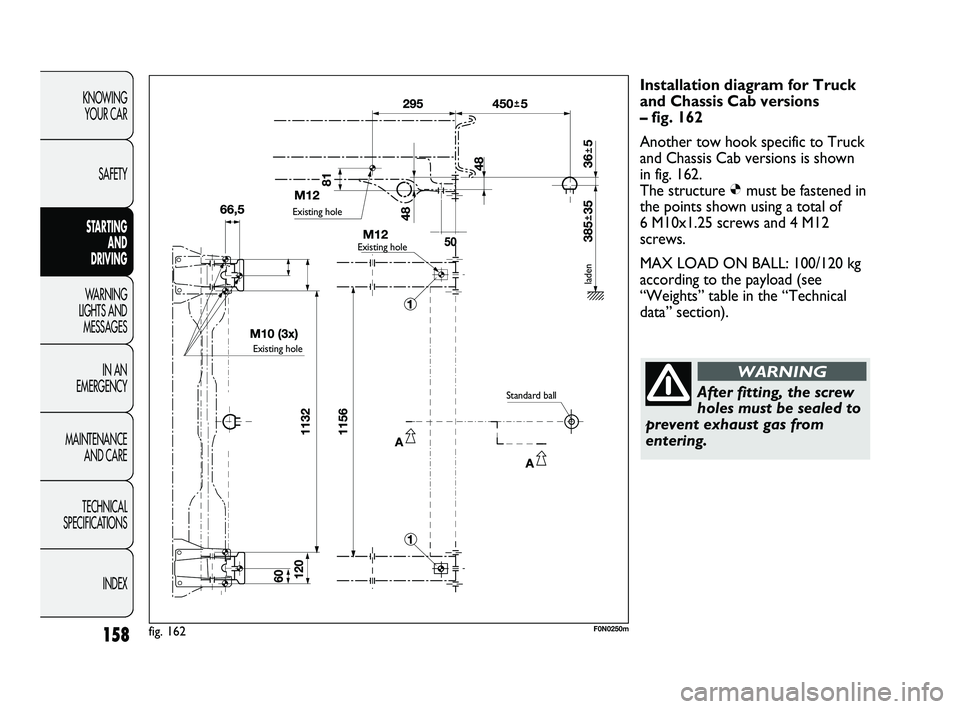
Installation diagram for Truck
and Chassis Cab versions
– fig. 162
Another tow hook specific to Truck
and Chassis Cab versions is shown
in fig. 162.
The structure Ømust be fastened in
the points shown using a total of
6 M10x1.25 screws and 4 M12
screws.
MAX LOAD ON BALL: 100/120 kg
according to the payload (see
“Weights” table in the “Technical
data” section).
After fitting, the screw
holes must be sealed to
prevent exhaust gas from
entering.
WARNING
fig. 162F0N0250m
Existing hole
Existing hole
Existing hole
Standard ball
laden
147-160 DUCATO LUM EN 7ed 6/21/10 2:13 PM Page 158
Page 185 of 286
184
KNOWING
YOUR CAR
SAFETY
STARTING
AND
DRIVING
WARNING
LIGHTS AND
MESSAGES
IN AN
EMERGENCY
MAINTENANCE
AND CARE
TECHNICAL
SPECIFICATIONS
INDEX
F0N0828mfig. 181
❒If at least 3 bar pressure is read, restore the correct
pressure specified in the paragraph „Inflation
pressure“ in the „Technical Specifications“ section
(with engine running and handbrake on) and restart.
❒drive with the utmost care to the nearest Fiat
Dealership.
You must inform the dealership that the
tyre has been repaired using the quick
tyre repair kit. Hand the leaflet over to the staff
who will be dealing with the the tyre treated
using the tyre repair kit.
WARNING
If different tyres from the ones supplied
with the vehicle are used, the repair
cannot be carried out. If the tyres are replaced,
it is advisable to use those approved by the
manufacturer. Contact a Fiat Dealership .
WARNING
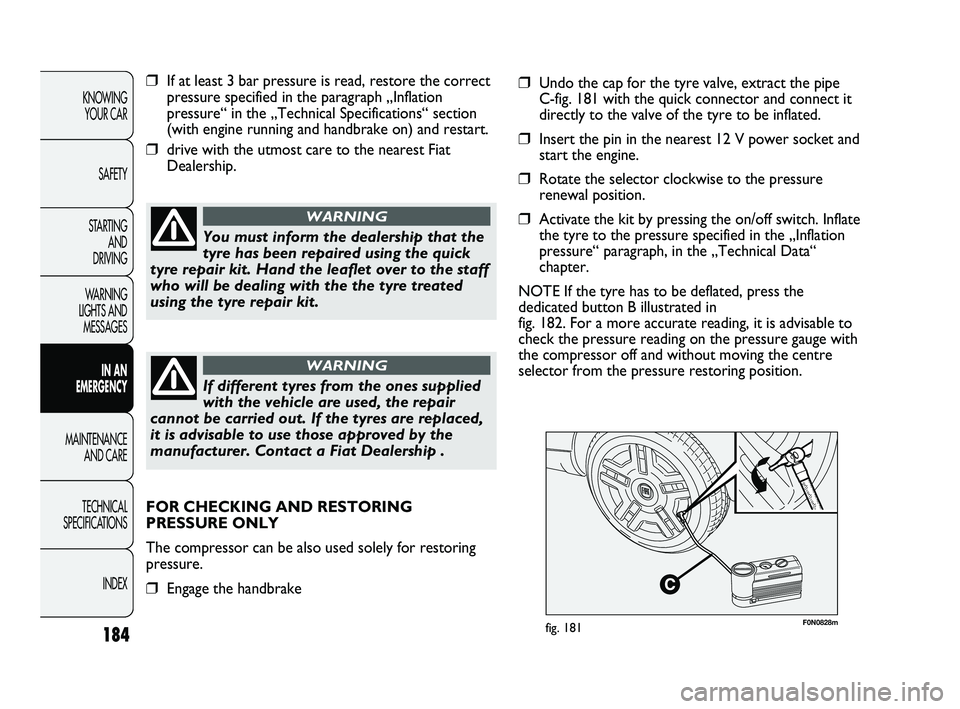
❒Undo the cap for the tyre valve, extract the pipe
C-fig. 181 with the quick connector and connect it
directly to the valve of the tyre to be inflated.
❒Insert the pin in the nearest 12 V power socket and
start the engine.
❒Rotate the selector clockwise to the pressure
renewal position.
❒Activate the kit by pressing the on/off switch. Inflate
the tyre to the pressure specified in the „Inflation
pressure“ paragraph, in the „Technical Data“
chapter.
NOTE If the tyre has to be deflated, press the
dedicated button B illustrated in
fig. 182. For a more accurate reading, it is advisable to
check the pressure reading on the pressure gauge with
the compressor off and without moving the centre
selector from the pressure restoring position.
FOR CHECKING AND RESTORING
PRESSURE ONLY
The compressor can be also used solely for restoring
pressure.
❒Engage the handbrake
173-206 DUCATO LUM EN 8ed 27-10-2010 15:45 Pagina 184
Page 232 of 286
231
KNOWING
YOUR CAR
SAFETY
STARTING
AND
DRIVING
WARNING
LIGHTS AND
MESSAGES
IN AN
EMERGENCY
MAINTENANCE
AND CARE
TECHNICAL
SPECIFICATIONS
INDEX
F0N0333mfig. 236
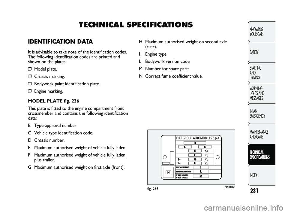
H Maximum authorised weight on second axle
(rear).
I Engine type
L Bodywork version code
M Number for spare parts
N Correct fume coefficient value.
TECHNICAL SPECIFICATIONS
IDENTIFICATION DATA
It is advisable to take note of the identification codes.
The following identification codes are printed and
shown on the plates:
❒Model plate.
❒Chassis marking.
❒Bodywork paint identification plate.
❒Engine marking.
MODEL PLATE fig. 236
This plate is fitted to the engine compartment front
crossmember and contains the following identification
data:
B Type-approval number
C Vehicle type identification code.
D Chassis number.
E Maximum authorised weight of vehicle fully laden.
F Maximum authorised weight of vehicle fully laden
plus trailer.
G Maximum authorised weight on first axle (front).
231-276 DUCATO LUM EN 9ed 15-04-2011 8:20 Pagina 231
Page 233 of 286
232
KNOWING
YOUR CAR
SAFETY
STARTING
AND
DRIVING
WARNING
LIGHTS AND
MESSAGES
IN AN
EMERGENCY
MAINTENANCE
AND CARE
TECHNICAL
SPECIFICATIONS
INDEX
F0N0160mfig. 237F0N0338mfig. 239
F0N0162mfig. 238
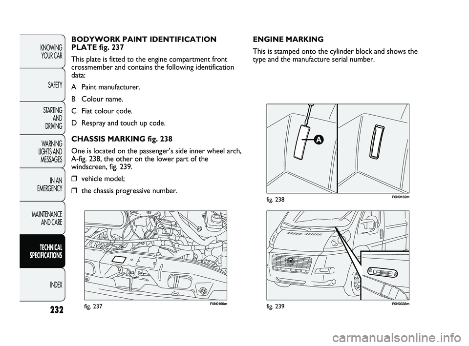
ENGINE MARKING
This is stamped onto the cylinder block and shows the
type and the manufacture serial number. BODYWORK PAINT IDENTIFICATION
PLATE fig. 237
This plate is fitted to the engine compartment front
crossmember and contains the following identification
data:
A Paint manufacturer.
B Colour name.
C Fiat colour code.
D Respray and touch up code.
CHASSIS MARKING fig. 238
One is located on the passenger’s side inner wheel arch,
A-fig. 238, the other on the lower part of the
windscreen, fig. 239.
❒vehicle model;
❒the chassis progressive number.
231-276 DUCATO LUM EN 9ed 15-04-2011 8:20 Pagina 232
Page 281 of 286
280
KNOWING
YOUR CAR
SAFETY
STARTING
AND
DRIVING
WARNING
LIGHTS AND
MESSAGES
IN AN
EMERGENCY
MAINTENANCE
AND CARE
TECHNICAL
SPECIFICATIONS
INDEX
Gearbox
– using the manual
gearbox ................................ 150
General warnings ..................... 2
Glove compartment ................ 91
Handbrake ................................149
Handbrake lever ...................... 149
Hazard lights ............................. 85
Headlight alignment
corrector ................................ 113
Headlight washers
– control ................................. 79
– maintenance ........................ 227
Headlights ..................................113
– adjusting headlights
abroad .................................. 114
– beam orientation ............... 113
– bulb replacement ............... 188
– headlight alignment
corrector ............................. 113Headlights
(warning for cleaning) ........... 229
Headrests .................................. 46
Heated rear window ............... 86
Heating and ventilation ........... 51
– automatic climate
control ................................. 60
– controls ................................ 52
– front window rapid
defrosting/demisting .. 54-57-65
– heated rear window
and external rear view
mirror defrosting/
demisting .....................54-59
– interior air recirculation ... 55
– passenger compartment
air vents ............................... 52
– manual climate control ...... 55
Heavy use of the vehicle
servicing ................................... 212
Hill Holder system .................. 117
Identification plates ................. 233
– body paintwork .................. 232
– identification data ............... 234
Ignition switch .......................... 12
– steering lock ........................ 13
In an emergency ....................... 173
Installation of electrical/
electronic devices .................. 125
Installing the tow hook ...........155
– assembly diagrams ..... 157-158
Instrument panel ...................... 14
Interior fittings ......................... 90
Interiors (maintenance) .......... 222
Isofix (child seat) ...................... 138
Keys ........................................... 5
– Code card ........................... 5
– key with remote control .. 6
– key without remote
control ................................. 8
– replacing the battery ......... 8
277-284 DUCATO LUM EN 9ed 15-04-2011 8:32 Pagina 280
Page 284 of 286
283
KNOWING
YOUR CAR
SAFETY
STARTING
AND
DRIVING
WARNING
LIGHTS AND
MESSAGES
IN AN
EMERGENCY
MAINTENANCE
AND CARE
TECHNICAL
SPECIFICATIONS
INDEX
Shelf above the cab ................. 96
Side air bags .............................. 143
Side lights
– control ................................. 74
– front bulb replacement ..... 189
– rear bulb replacement ...... 192
– side bulb replacement ....... 196
Ski rack ...................................... 112
Sliding side door ...................... 106
Sliding side window ................. 106
Snow chains .............................. 159
Speed block ............................... 102
Speedometer ............................ 15
Starting the engine ................... 147
– bump starting ...................... 174
– emergency starting ............ 173
– ignition switch ..................... 12
– jump starting ....................... 173
– procedure ............................ 147
– stopping the engine ........... 148
– warming up the engine
once started ........................148Starting up and driving ............ 147
Steering lock ............................. 13
Steering wheel
(adjustment) ........................... 47
Steering
– technical specifications ...... 236
– turning circle ....................... 236
Storage compartments ..... 90-91
Sun visors .................................. 95
Supply (specifications) ............. 235
Suspension (specifications) .... 235
Symbols ...................................... 4
Tachograph ..............................101
Technical specifications .......... 231
Telepass (preparation) ............ 126
Third brake light ...................... 195
Towing the vehicle .................. 205
Trailer (towing) ....................... 154
– installing the tow hook ..... 155
– warnings ...............................155Transmission
(specifications) ....................... 235
Trip computer .......................... 35
TV camera system and rear
visibility display ....................... 98
Tyre inflation pressure ........... 240
Tyres
– changing a wheel ................ 174
– maintenance ........................ 224
– provided ...............................239
– reading tyre markings ....... 237
– Rim Protector .................... 238
– snow ..................................... 159
– tyre inflation pressure ....... 240
Under-seat compartment ..... 42
Vehicle identification data ...... 231
Vehicle inactivity ...................... 160
Ventilation ................................. 51
277-284 DUCATO LUM EN 9ed 15-04-2011 8:32 Pagina 283
Page 286 of 286
The data contained in this publication is intended merely as a guide. FIAT reserves the right to modify the models and
versions described in this booklet at any time for technical and commercial reasons.
If you have any further questions please consult your FIAT dealer.
Printed in recycled paper without chlorine.
OWNER HANDBOOK
FIATDUCATO
ENGLISH
DUCATO LUM GB 17-12-2008 9:57 Pagina 1