technical data FIAT DUCATO 2010 Owner handbook (in English)
[x] Cancel search | Manufacturer: FIAT, Model Year: 2010, Model line: DUCATO, Model: FIAT DUCATO 2010Pages: 286, PDF Size: 12.53 MB
Page 1 of 286

The data contained in this publication is intended merely as a guide. FIAT reserves the right to modify the models and
versions described in this booklet at any time for technical and commercial reasons.
If you have any further questions please consult your FIAT dealer.
Printed in recycled paper without chlorine.
OWNER HANDBOOK
FIATDUCATO
ENGLISH
DUCATO LUM GB 17-12-2008 9:57 Pagina 1
Page 19 of 286
F0N0016mfig. 17
DIGITAL DISPLAY
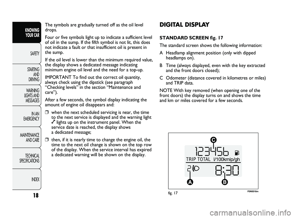
STANDARD SCREEN fig. 17
The standard screen shows the following information:
A Headlamp alignment position (only with dipped
headlamps on).
B Time (always displayed, even with the key extracted
and the front doors closed);
C Odometer (distance covered in kilometres or miles)
and TRIP data.
NOTE With key removed (when opening one of the
front doors) the display turns on and shows the time
and km or miles covered for a few seconds. The symbols are gradually turned off as the oil level
drops.
Four or five symbols light up to indicate a sufficient level
of oil in the sump. If the fifth symbol is not lit, this does
not indicate a fault or that insufficient oil is present in
the sump.
If the oil level is lower than the minimum required value,
the display shows a dedicated message indicating
minimum engine oil level and the need for a top-up.
IMPORTANT To find out the correct oil quantity,
always check using the dipstick (see paragraph
“Checking levels” in the section “Maintenance and
care”).
After a few seconds, the symbol display indicating the
amount of engine oil disappears and:
❒when the next scheduled servicing is near, the time
to the next service is displayed and the warning light
õlights up on the instrument panel. When the
service date is reached, the display shows
a dedicated message;
❒then, if it is nearly time to change the engine oil, the
time to the next oil change is shown on the top row
of the display. When the service interval has expired
a dedicated warning will be shown on the display.
18
KNOWING
YOUR CAR
SAFETY
STARTING
AND
DRIVING
WARNING
LIGHTS AND
MESSAGES
IN AN
EMERGENCY
MAINTENANCE
AND CARE
TECHNICAL
SPECIFICATIONS
INDEX
001-036 DUCATO LUM EN 7ed 6/21/10 2:08 PM Page 18
Page 28 of 286
27
KNOWING
YOUR CAR
SAFETY
STARTING
AND
DRIVING
WARNING
LIGHTS AND
MESSAGES
IN AN
EMERGENCY
MAINTENANCE
AND CARE
TECHNICAL
SPECIFICATIONS
INDEX
Day
YearMonth
Deutsch
Français
English
Español
Italiano
Nederland
Português Example:
fig. 23 Example:
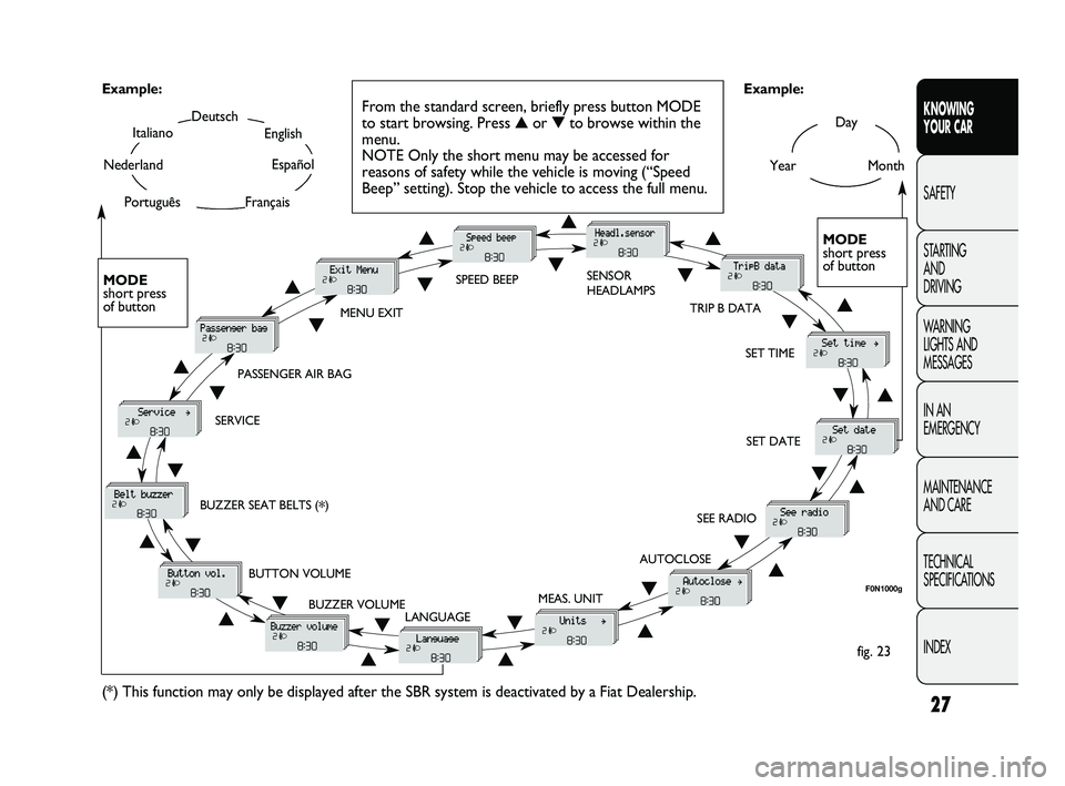
From the standard screen, briefly press button MODE
to start browsing. Press ▲or ▼to browse within the
menu.
NOTE Only the short menu may be accessed for
reasons of safety while the vehicle is moving (“Speed
Beep” setting). Stop the vehicle to access the full menu.
F0N1000g
MODE
short press
of button
▲
▼
MENU EXITSPEED BEEPSENSOR
HEADLAMPS
SET TIME
SET DATE
SEE RADIO
AUTOCLOSE
MEAS. UNIT
LANGUAGE BUZZER VOLUME BUTTON VOLUME BUZZER SEAT BELTS (
*) SERVICEPASSENGER AIR BAG
(*) This function may only be displayed after the SBR system is deactivated by a Fiat Dealership.
TRIP B DATA
MODE
short press
of button
▲
▼▲
▼▲
▼
▲
▼
▲ ▼
▲ ▼ ▲
▼
▲
▼
▲
▼
▲▼
▲▼
▲▼
▲▼▼
▲
001-036 DUCATO LUM EN 7ed 6/21/10 2:09 PM Page 27
Page 30 of 286
29
KNOWING
YOUR CAR
SAFETY
STARTING
AND
DRIVING
WARNING
LIGHTS AND
MESSAGES
IN AN
EMERGENCY
MAINTENANCE
AND CARE
TECHNICAL
SPECIFICATIONS
INDEX
– once you have selected the submenu to be changed,
press the button MODE briefly;
– when accessing the “Time” submenu:briefly press the
button MODE, “hours” will flash on the display;
– press button
▲or ▼to adjust;
– briefly press button MODE: “minutes” starts flashing
on the display;
– press button
▲or ▼to adjust;
– when accessing the “Format” submenu:briefly press
button MODE : the previously set display format will
flash on the display;
– press
▲or ▼to select 24h or 12h.
When you have made the required settings, briefly press
the MODE button to go back to the submenu screen or
hold the button down to go back to the main menu
screen without storing the new settings.
– press the MODE button again for a while to return to
the standard screen or to the main menu according to
where you are in the menu. Trip B On/Off (trip B data)
This function can be used to activate (On) or deactivate
(Off) the Trip B display (partial trip).
For further information see “Trip computer”.
Proceed as follows to switch the function on and off:
– briefly press button MODE: ON or OFF flashes on
the display (according to the previous setting);
– press button
▲or ▼to select;
– press the MODE button briefly to return to the menu
screen or press the button for longer to return to the
standard screen without memorising.
Setting the clock (Set time)
This function enables the clock to be set through two
submenus: “Time” and “Format”.
To carry out the adjustment, proceed as follows:
– briefly press the MODE button and two submenus,
“Time” and “Format”, are displayed;
– press
▲or ▼to move between the two submenus;
001-036 DUCATO LUM EN 7ed 6/21/10 2:09 PM Page 29
Page 102 of 286
101
KNOWING
YOUR CAR
SAFETY
STARTING
AND
DRIVING
WARNING
LIGHTS AND
MESSAGES
IN AN
EMERGENCY
MAINTENANCE
AND CARE
TECHNICAL
SPECIFICATIONS
INDEX
TACHOGRAPH
For tachograph operation and use, consult the owner
handbook supplied by the device manufacturer.
The tachograph must be installed on the vehicle when
the vehicle weight (with or without trailer) exceeds
3.5 tons.
IMPORTANT Anyone making changes to the
monitoring device or signal transmission system that
affects recording by the monitoring instrument,
particularly if this is done for purposes of fraud, may be
in breach of criminal or administrative state regulations.
IMPORTANT If a tachograph is fitted, if the vehicle is
parked for more than 5 days, it is advisable to
disconnect the negative battery terminal to maintain its
charge.
IMPORTANT NOTES
Do not use abrasive detergents or solvents to clean the
device. To clean the outside of the device, use a damp
cloth or special products for the care of synthetic
materials.The tachograph is installed and sealed by authorised
personnel: do not try and access the device or the
supply and recording leads in any way. It is the
responsibility of the owner of the vehicle on which the
tachograph is installed to check the device regularly.
The check must be carried out at least every two years
and a test must be carried out to ensure that it is
working properly. Ensure that the data label is renewed
after every check that that the label contains the
specified data.
037-128 DUCATO LUM EN 7ed 6/21/10 2:11 PM Page 101
Page 114 of 286
113
KNOWING
YOUR CAR
SAFETY
STARTING
AND
DRIVING
WARNING
LIGHTS AND
MESSAGES
IN AN
EMERGENCY
MAINTENANCE
AND CARE
TECHNICAL
SPECIFICATIONS
INDEX
HEADLIGHTS
HEADLIGHT BEAM AIMING
The correct direction of the headlights is essential for
the comfort and safety of the driver and other road
users. To ensure the best visibility when travelling with
the headlights on, the headlight alignment must be
correct. Contact a Fiat Dealership to have the
headlights properly adjusted.
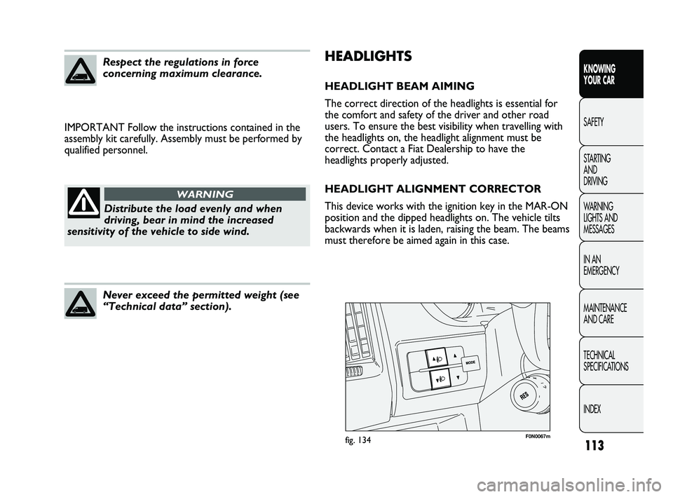
HEADLIGHT ALIGNMENT CORRECTOR
This device works with the ignition key in the MAR-ON
position and the dipped headlights on. The vehicle tilts
backwards when it is laden, raising the beam. The beams
must therefore be aimed again in this case. IMPORTANT Follow the instructions contained in the
assembly kit carefully. Assembly must be performed by
qualified personnel.
Respect the regulations in force
concerning maximum clearance.
Distribute the load evenly and when
driving, bear in mind the increased
sensitivity of the vehicle to side wind.
WARNING
Never exceed the permitted weight (see
“Technical data” section).
F0N0067mfig. 134
037-128 DUCATO LUM EN 7ed 6/21/10 2:11 PM Page 113
Page 129 of 286
128
KNOWING
YOUR CAR
SAFETY
STARTING
AND
DRIVING
WARNING
LIGHTS AND
MESSAGES
IN AN
EMERGENCY
MAINTENANCE
AND CARE
TECHNICAL
SPECIFICATIONS
INDEX
DIESEL PARTICULATE FILTER (DPF)
The Diesel Particulate Filter is a mechanical filter,
integral with the exhaust system, that physically traps
particulates present in the exhaust gases of diesel
engines.
The diesel particulate filter has been adopted to
eliminate almost all particulates in compliance with
current/future legal regulations.
During normal use of the vehicle, the engine
management control unit records a set of data (travel
time, type of route, temperatures, etc.) and it will
then calculate how much particulate has been trapped
by the filter.
Since this filter physically traps particulate, it should be
regenerated (cleaned) at regular intervals by burning
carbon particles.
The regeneration procedure is controlled automatically
by the engine management control unit according to the
filter conditions and vehicle use conditions.
There may be a limited increase in the engine idle speed
during the regeneration, a limited increase in fumes and
high temperatures at the exhaust. These are not faults;
they do not impair vehicle performance or damage the
environment.
If the dedicated message is displayed, refer to the
“Warning lights and messages” section.PROTECTING THE ENVIRONMENT
The following devices are used for reducing diesel fuel
engine emissions:
❒oxidising catalytic converter;
❒exhaust gas recirculation system (E.G.R.);
❒diesel particulate filter (DPF).
The diesel particulate filter (DPF)
reaches high temperatures during
operation. Therefore do not therefore park the
vehicle on inflammable materials (grass, dry
leaves, pine needles, etc.): fire hazard.
WARNING
The catalytic converter also reaches
high temperatures during normal
operation. Do not park the car on grass, dry
leaves, pine needles or other flammable
material: fire hazard.
WARNING
037-128 DUCATO LUM EN 7ed 6/21/10 2:11 PM Page 128
Page 135 of 286
Over 1.50 m in height, from the point of view of
restraint systems, children are considered as adults and
wear the seat belts normally.
134
KNOWING
YOUR CAR
SAFETY
STARTING
AND
DRIVING
WARNING
LIGHTS AND
MESSAGES
IN AN
EMERGENCY
MAINTENANCE
AND CARE
TECHNICAL
SPECIFICATIONS
INDEX
CARRYING CHILDREN SAFELY
For optimal protection in the event of a collision, all
passengers must be seated and wearing adequate
restraint systems. This is even more important for
children. This prescription is compulsory in all EU
countries pursuant to Directive 2003/20/EC.
Compared with adults, a child’s head is proportionally
larger and heavier than the rest of the body, while
muscles and bone structure are not fully developed.
Therefore, correct restraint systems are necessary
which are different from adult seat belts. The results of
research in relation to the best protection for children
is summarised in European Regulation EEC-R44, which
divides the restraint systems into five groups in addition
to making their use compulsory:
Group 0 up to 10 kg of weight
Group 0+ up to 13 kg of weight
Group 1 9–18 kg in weight
Group 2 15–25 kg in weight
Group 3 22–36 kg of weight
As you can see, the groups overlap partly and, in fact,
there are devices on sale that cover more than one
weight group. All child restraint devices must bear the
certification data, together with the control mark,
on a label solidly fixed to the seat which must never be
removed.
Do not place a cradle seat facing
backwards on the front seat if the
passenger side airbag is on. Deployment of the
airbag in an accident could cause fatal injuries
to the baby regardless of the severity of the
collision. It is advisable to always carry children
in dedicated child seats on the rear seat, which
is the most protected position in the event of an
accident.
WARNING
SERIOUS DANGER Should it be
absolutely necessary to carry a child on
the front seat in a backwards-facing
child seat, the passenger’s front and side
airbags must be deactivated through the
setup menu. Deactivation can be verified by
checking the Fwarning light on the
instrument panel. Move the passenger’s seat as
far back as possible to avoid contact between
the child seat and the dashboard.
WARNING
129-146 DUCATO LUM EN 7ed 6/21/10 2:12 PM Page 134
Page 152 of 286
151
KNOWING
YOUR CAR
SAFETY
STARTING
AND
DRIVING
WARNING
LIGHTS AND
MESSAGES
IN AN
EMERGENCY
MAINTENANCE
AND CARE
TECHNICAL
SPECIFICATIONS
INDEX
IMPORTANT For versions with right and left side flaps,
it is advisable to reposition the release lever in the
closed position before lowering the sides.
LOAD ADVICE
The Fiat Ducato version used by you has been designed
and type approved on the basis of certain maximum
weights (see “Weights” table in the “Technical Data”
section): kerb weight, payload, total weight, maximum
weight on front axle, maximum weight on rear axle,
towable weight.
Each of these must be strictly observed
and MUST NEVER BE EXCEEDED in
any case. In particular, ensure that you never
exceed the maximum permitted weights on the
front and rear axles when arranging the load on
the vehicle (particularly if the vehicle is
equipped with a specific trim level).
WARNING
IMPORTANT The maximum permitted load on the
floor fastenings is 500 kg; the maximum permitted load
on the side panel is 150 kg.
Irregular trajectories and abrupt braking
may cause sudden movements of the
load with consequent situations of hazard for
the driver and passengers: before setting off,
secure the load tightly using the appropriate
hooks on the floor and use steel cables, ropes
or chains strong enough to hold the items to be
secured.
WARNING
If a vehicle is parked on a very steep
gradient or with a side gradient, opening
the rear door or side door could cause any
unsecured items to emerge suddenly.
WARNING
147-160 DUCATO LUM EN 7ed 6/21/10 2:13 PM Page 151
Page 158 of 286
157
KNOWING
YOUR CAR
SAFETY
STARTING
AND
DRIVING
WARNING
LIGHTS AND
MESSAGES
IN AN
EMERGENCY
MAINTENANCE
AND CARE
TECHNICAL
SPECIFICATIONS
INDEX
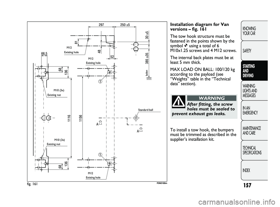
Installation diagram for Van
versions – fig. 161
The tow hook structure must be
fastened in the points shown by the
symbol Øusing a total of 6
M10x1.25 screws and 4 M12 screws.
The internal back plates must be at
least 5 mm thick.
MAX LOAD ON BALL: 100/120 kg
according to the payload (see
“Weights” table in the “Technical
data” section).
After fitting, the screw
holes must be sealed to
prevent exhaust gas leaks.
WARNING
fig. 161F0N0189m
Existing hole
Existing nut
Existing nutExisting hole
Existing hole
laden
Standard ball M12
M12
M10 (3x)
M10 (3x)
M12
To install a tow hook, the bumpers
must be trimmed as described in the
supplier’s installation kit.
147-160 DUCATO LUM EN 7ed 6/21/10 2:13 PM Page 157