technical specifications FIAT DUCATO 2010 Owner handbook (in English)
[x] Cancel search | Manufacturer: FIAT, Model Year: 2010, Model line: DUCATO, Model: FIAT DUCATO 2010Pages: 286, PDF Size: 12.53 MB
Page 195 of 286
F0N0241mfig. 198
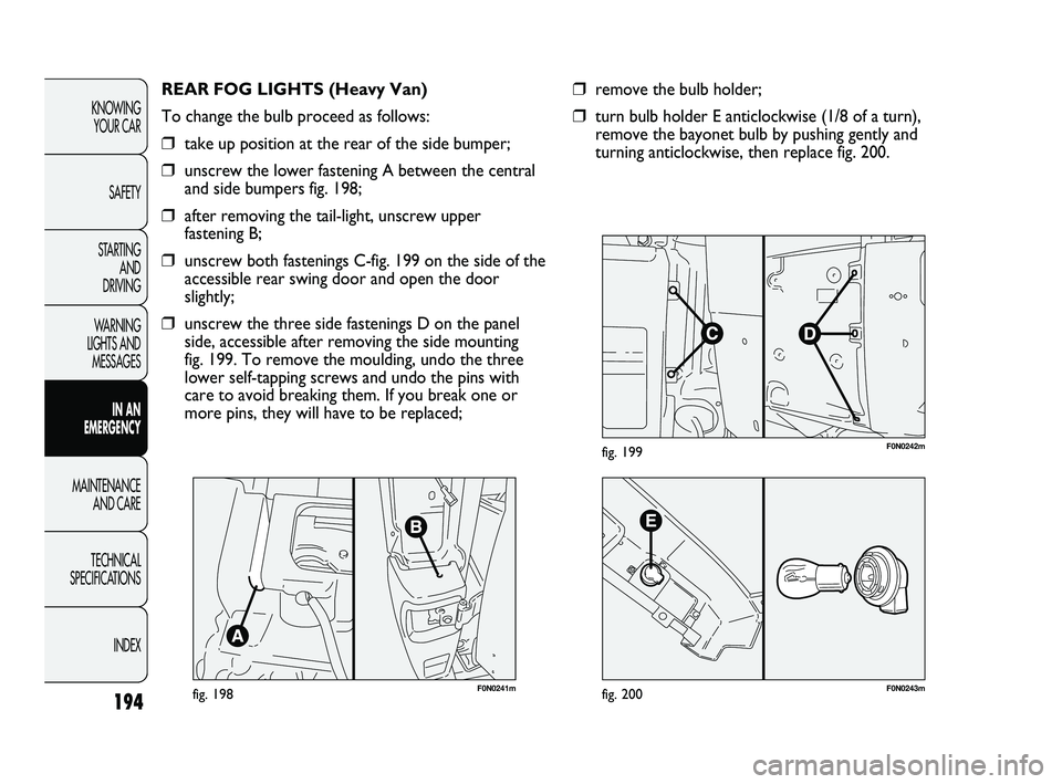
REAR FOG LIGHTS (Heavy Van)
To change the bulb proceed as follows:
❒take up position at the rear of the side bumper;
❒unscrew the lower fastening A between the central
and side bumpers fig. 198;
❒after removing the tail-light, unscrew upper
fastening B;
❒unscrew both fastenings C-fig. 199 on the side of the
accessible rear swing door and open the door
slightly;
❒unscrew the three side fastenings D on the panel
side, accessible after removing the side mounting
fig. 199. To remove the moulding, undo the three
lower self-tapping screws and undo the pins with
care to avoid breaking them. If you break one or
more pins, they will have to be replaced;
194
KNOWING
YOUR CAR
SAFETY
STARTING
AND
DRIVING
WARNING
LIGHTS AND
MESSAGES
IN AN
EMERGENCY
MAINTENANCE
AND CARE
TECHNICAL
SPECIFICATIONS
INDEX
F0N0242mfig. 199
F0N0243mfig. 200
❒remove the bulb holder;
❒turn bulb holder E anticlockwise (1/8 of a turn),
remove the bayonet bulb by pushing gently and
turning anticlockwise, then replace fig. 200.
173-206 DUCATO LUM EN 8ed 27-10-2010 15:45 Pagina 194
Page 196 of 286
195
KNOWING
YOUR CAR
SAFETY
STARTING
AND
DRIVING
WARNING
LIGHTS AND
MESSAGES
IN AN
EMERGENCY
MAINTENANCE
AND CARE
TECHNICAL
SPECIFICATIONS
INDEX
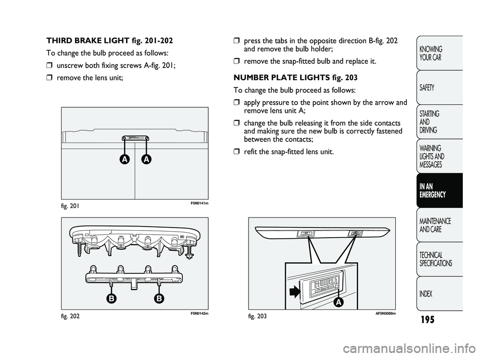
❒press the tabs in the opposite direction B-fig. 202
and remove the bulb holder;
❒remove the snap-fitted bulb and replace it.
NUMBER PLATE LIGHTS fig. 203
To change the bulb proceed as follows:
❒apply pressure to the point shown by the arrow and
remove lens unit A;
❒change the bulb releasing it from the side contacts
and making sure the new bulb is correctly fastened
between the contacts;
❒refit the snap-fitted lens unit. THIRD BRAKE LIGHT fig. 201-202
To change the bulb proceed as follows:
❒unscrew both fixing screws A-fig. 201;
❒remove the lens unit;
F0N0141mfig. 201
F0N0142mfig. 202AF0N0089mfig. 203
173-206 DUCATO LUM EN 8ed 27-10-2010 15:45 Pagina 195
Page 197 of 286
F0N0244mfig. 204
CHANGING AN INTERIOR LIGHT
For the type of bulb and relevant power rating, see
“Changing a bulb”.
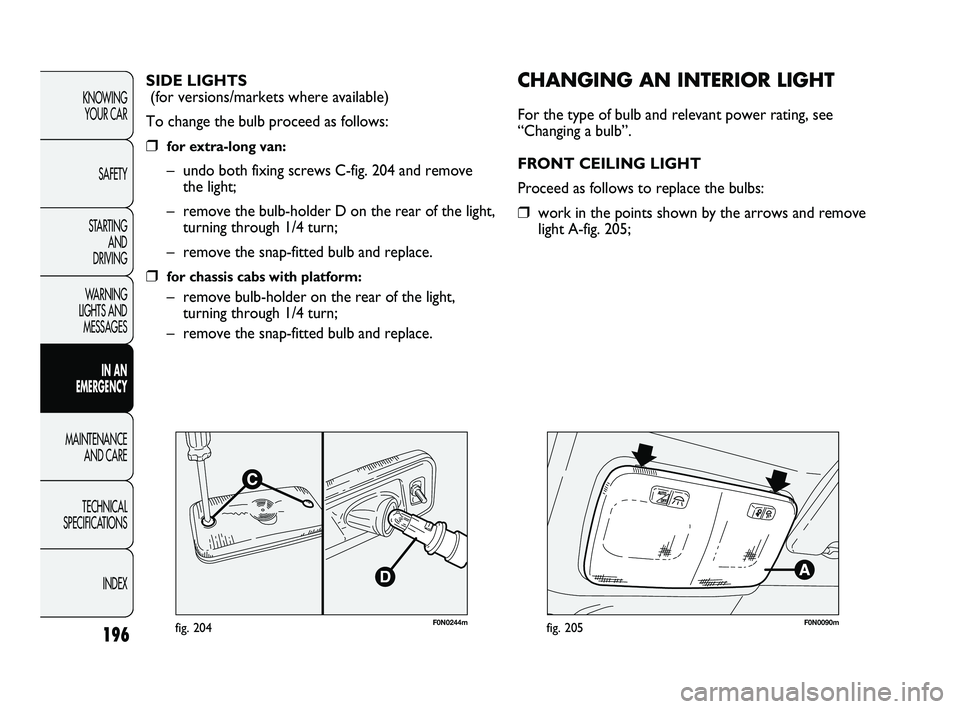
FRONT CEILING LIGHT
Proceed as follows to replace the bulbs:
❒work in the points shown by the arrows and remove
light A-fig. 205; SIDE LIGHTS
(for versions/markets where available)
To change the bulb proceed as follows:
❒for extra-long van:
– undo both fixing screws C-fig. 204 and remove
the light;
– remove the bulb-holder D on the rear of the light,
turning through 1/4 turn;
– remove the snap-fitted bulb and replace.
❒for chassis cabs with platform:
– remove bulb-holder on the rear of the light,
turning through 1/4 turn;
– remove the snap-fitted bulb and replace.
196
KNOWING
YOUR CAR
SAFETY
STARTING
AND
DRIVING
WARNING
LIGHTS AND
MESSAGES
IN AN
EMERGENCY
MAINTENANCE
AND CARE
TECHNICAL
SPECIFICATIONS
INDEX
F0N0090mfig. 205
173-206 DUCATO LUM EN 8ed 27-10-2010 15:45 Pagina 196
Page 198 of 286
197
KNOWING
YOUR CAR
SAFETY
STARTING
AND
DRIVING
WARNING
LIGHTS AND
MESSAGES
IN AN
EMERGENCY
MAINTENANCE
AND CARE
TECHNICAL
SPECIFICATIONS
INDEX
F0N0091mfig. 206
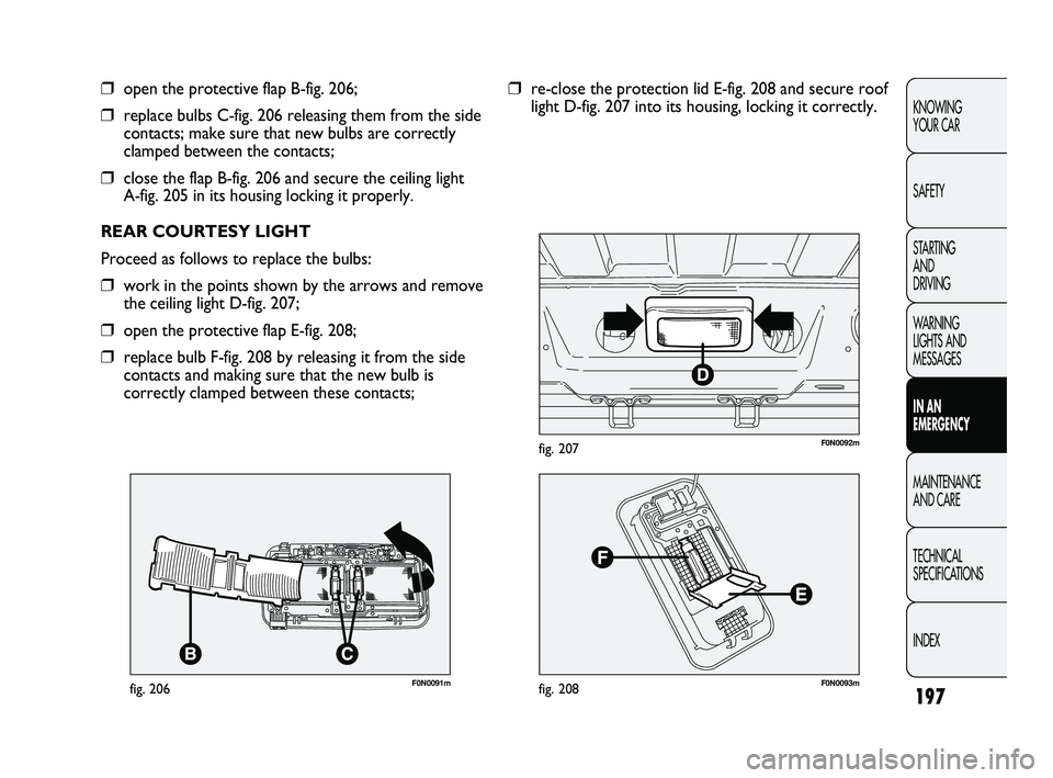
❒open the protective flap B-fig. 206;
❒replace bulbs C-fig. 206 releasing them from the side
contacts; make sure that new bulbs are correctly
clamped between the contacts;
❒close the flap B-fig. 206 and secure the ceiling light
A-fig. 205 in its housing locking it properly.
REAR COURTESY LIGHT
Proceed as follows to replace the bulbs:
❒work in the points shown by the arrows and remove
the ceiling light D-fig. 207;
❒open the protective flap E-fig. 208;
❒replace bulb F-fig. 208 by releasing it from the side
contacts and making sure that the new bulb is
correctly clamped between these contacts;
F0N0093mfig. 208
F0N0092mfig. 207
❒re-close the protection lid E-fig. 208 and secure roof
light D-fig. 207 into its housing, locking it correctly.
173-206 DUCATO LUM EN 8ed 27-10-2010 15:45 Pagina 197
Page 199 of 286
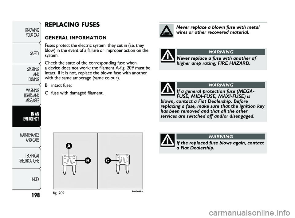
F0N0094mfig. 209
REPLACING FUSES
GENERAL INFORMATION
Fuses protect the electric system: they cut in (i.e. they
blow) in the event of a failure or improper action on the
system.
Check the state of the corresponding fuse when
a device does not work: the filament A-fig. 209 must be
intact. If it is not, replace the blown fuse with another
with the same amperage (same colour).
B intact fuse;
C fuse with damaged filament.
198
KNOWING
YOUR CAR
SAFETY
STARTING
AND
DRIVING
WARNING
LIGHTS AND
MESSAGES
IN AN
EMERGENCY
MAINTENANCE
AND CARE
TECHNICAL
SPECIFICATIONS
INDEX
Never replace a blown fuse with metal
wires or other recovered material.
Never replace a fuse with another of
higher amp rating; FIRE HAZARD.
WARNING
If a general protection fuse (MEGA-
FUSE, MIDI-FUSE, MAXI-FUSE) is
blown, contact a Fiat Dealership. Before
replacing a fuse, make sure that the ignition key
has been removed and that all the other
services are switched off and/or disengaged.
WARNING
If the replaced fuse blows again, contact
a Fiat Dealership.
WARNING
173-206 DUCATO LUM EN 8ed 27-10-2010 15:45 Pagina 198
Page 200 of 286
199
KNOWING
YOUR CAR
SAFETY
STARTING
AND
DRIVING
WARNING
LIGHTS AND
MESSAGES
IN AN
EMERGENCY
MAINTENANCE
AND CARE
TECHNICAL
SPECIFICATIONS
INDEX
If a general protection fuse for safety
systems (air bag system, braking system),
power unit systems (engine system, gearbox
system) or steering system blows, contact a Fiat
Dealership.
WARNING
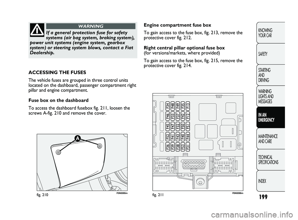
F0N0095mfig. 210F0N0096mfig. 211
Engine compartment fuse box
To gain access to the fuse box, fig. 213, remove the
protective cover fig. 212.
Right central pillar optional fuse box
(for versions/markets, where provided)
To gain access to the fuse box, fig. 215, remove the
protective cover fig. 214.
ACCESSING THE FUSES
The vehicle fuses are grouped in three control units
located on the dashboard, passenger compartment right
pillar and engine compartment.
Fuse box on the dashboard
To access the dashboard fusebox fig. 211, loosen the
screws A-fig. 210 and remove the cover.
173-206 DUCATO LUM EN 8ed 27-10-2010 15:45 Pagina 199
Page 201 of 286
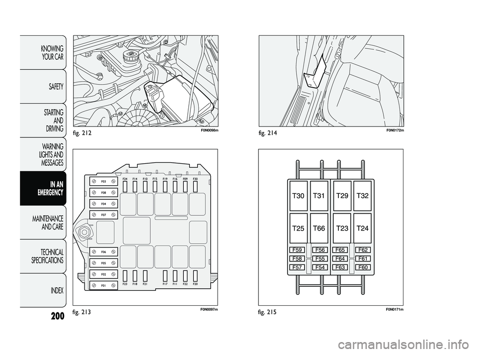
F0N0098mfig. 212
F0N0097mfig. 213
F0N0172mfig. 214
F0N0171mfig. 215200
KNOWING
YOUR CAR
SAFETY
STARTING
AND
DRIVING
WARNING
LIGHTS AND
MESSAGES
IN AN
EMERGENCY
MAINTENANCE
AND CARE
TECHNICAL
SPECIFICATIONS
INDEX
173-206 DUCATO LUM EN 8ed 27-10-2010 15:45 Pagina 200
Page 202 of 286
201
KNOWING
YOUR CAR
SAFETY
STARTING
AND
DRIVING
WARNING
LIGHTS AND
MESSAGES
IN AN
EMERGENCY
MAINTENANCE
AND CARE
TECHNICAL
SPECIFICATIONS
INDEX
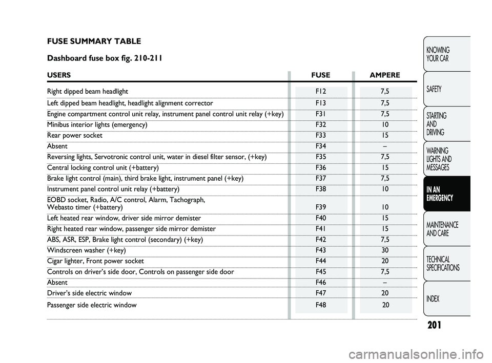
FUSE SUMMARY TABLE
Dashboard fuse box fig. 210-211
USERSFUSE AMPERE
Right dipped beam headlight F12 7,5
Left dipped beam headlight, headlight alignment corrector F13 7,5
Engine compartment control unit relay, instrument panel control unit relay (+key) F31 7,5
Minibus interior lights (emergency) F32 10
Rear power socket F33 15
AbsentF34 –
Reversing lights, Servotronic control unit, water in diesel filter sensor, (+key) F35 7,5
Central locking control unit (+battery) F36 15
Brake light control (main), third brake light, instrument panel (+key) F37 7,5
Instrument panel control unit relay (+battery) F38 10
EOBD socket, Radio, A/C control, Alarm, Tachograph,
Webasto timer (+battery) F39 10
Left heated rear window, driver side mirror demister F40 15
Right heated rear window, passenger side mirror demister F41 15
ABS, ASR, ESP, Brake light control (secondary) (+key) F42 7,5
Windscreen washer (+key) F43 30
Cigar lighter, Front power socket F44 20
Controls on driver’s side door, Controls on passenger side door F45 7,5
AbsentF46 –
Driver’s side electric window F47 20
Passenger side electric window F48 20
173-206 DUCATO LUM EN 8ed 27-10-2010 15:45 Pagina 201
Page 203 of 286
202
KNOWING
YOUR CAR
SAFETY
STARTING
AND
DRIVING
WARNING
LIGHTS AND
MESSAGES
IN AN
EMERGENCY
MAINTENANCE
AND CARE
TECHNICAL
SPECIFICATIONS
INDEX
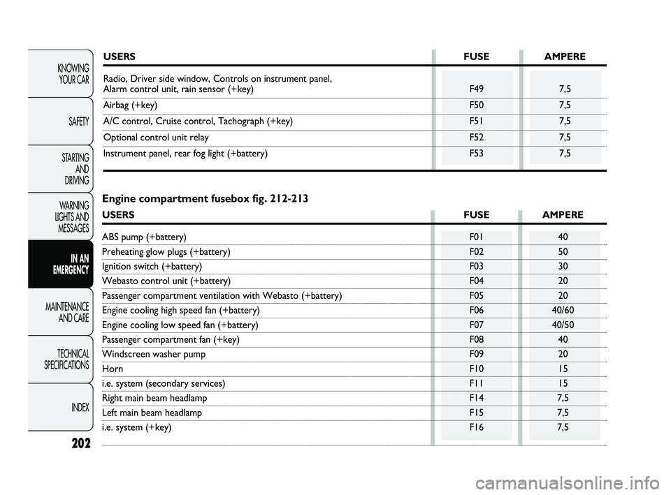
USERSFUSE AMPERE
Radio, Driver side window, Controls on instrument panel,
Alarm control unit, rain sensor (+key) F49 7,5
Airbag (+key) F50 7,5
A/C control, Cruise control, Tachograph (+key) F51 7,5
Optional control unit relay F52 7,5
Instrument panel, rear fog light (+battery) F53 7,5
Engine compartment fusebox fig. 212-213
USERSFUSE AMPERE
ABS pump (+battery) F01 40
Preheating glow plugs (+battery) F02 50
Ignition switch (+battery) F03 30
Webasto control unit (+battery) F04 20
Passenger compartment ventilation with Webasto (+battery) F05 20
Engine cooling high speed fan (+battery) F06 40/60
Engine cooling low speed fan (+battery) F07 40/50
Passenger compartment fan (+key) F08 40
Windscreen washer pump F09 20
HornF10 15
i.e. system (secondary services) F11 15
Right main beam headlamp F14 7,5
Left main beam headlamp F15 7,5
i.e. system (+key) F16 7,5
173-206 DUCATO LUM EN 8ed 27-10-2010 15:45 Pagina 202
Page 204 of 286
203
KNOWING
YOUR CAR
SAFETY
STARTING
AND
DRIVING
WARNING
LIGHTS AND
MESSAGES
IN AN
EMERGENCY
MAINTENANCE
AND CARE
TECHNICAL
SPECIFICATIONS
INDEX
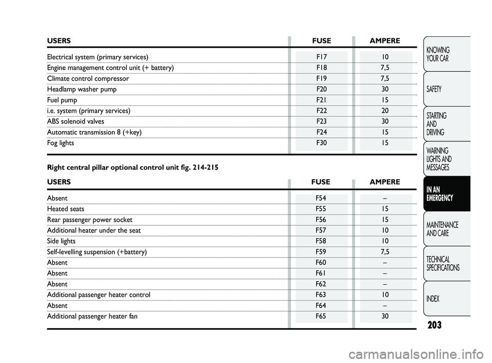
USERSFUSE AMPERE
Electrical system (primary services) F17 10
Engine management control unit (+ battery) F18 7,5
Climate control compressor F19 7,5
Headlamp washer pump F20 30
Fuel pumpF21 15
i.e. system (primary services) F22 20
ABS solenoid valves F23 30
Automatic transmission 8 (+key) F24 15
Fog lightsF30 15
Right central pillar optional control unit fig. 214-215
USERSFUSE AMPERE
AbsentF54 –
Heated seatsF55 15
Rear passenger power socket F56 15
Additional heater under the seat F57 10
Side lightsF58 10
Self-levelling suspension (+battery) F59 7,5
AbsentF60 –
AbsentF61 –
AbsentF62 –
Additional passenger heater control F63 10
AbsentF64 –
Additional passenger heater fan F65 30
173-206 DUCATO LUM EN 8ed 27-10-2010 15:45 Pagina 203