sensor FIAT DUCATO 2010 Owner handbook (in English)
[x] Cancel search | Manufacturer: FIAT, Model Year: 2010, Model line: DUCATO, Model: FIAT DUCATO 2010Pages: 286, PDF Size: 12.53 MB
Page 12 of 286
11
KNOWING
YOUR CAR
SAFETY
STARTING
AND
DRIVING
WARNING
LIGHTS AND
MESSAGES
IN AN
EMERGENCY
MAINTENANCE
AND CARE
TECHNICAL
SPECIFICATIONS
INDEX
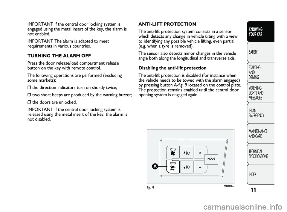
F0N0232mfig. 9
ANTI-LIFT PROTECTION
The anti-lift protection system consists in a sensor
which detects any change in vehicle tilting with a view
to identifying any possible vehicle lifting, even partial
(e.g. when a tyre is removed).
The sensor also detects minor changes in the vehicle
angle both along the longitudinal and transverse axis.
Disabling the anti-lift protection
The anti-lift protection is disabled (for instance when
the vehicle needs to be towed with the alarm engaged)
by pressing button A-fig. 9 located on the control plate.
The protection remains enabled until the central door
opening system is engaged again. IMPORTANT If the central door locking system is
engaged using the metal insert of the key, the alarm is
not enabled.
IMPORTANT The alarm is adapted to meet
requirements in various countries.
TURNING THE ALARM OFF
Press the door release/load compartment release
button on the key with remote control.
The following operations are performed (excluding
some markets):
❒the direction indicators turn on shortly twice;
❒two short beeps are produced by the warning buzzer;
❒the doors are unlocked.
IMPORTANT If the central door locking system is
released using the metal insert of the key, the alarm is
not disabled.
001-036 DUCATO LUM EN 7ed 6/21/10 2:08 PM Page 11
Page 28 of 286
27
KNOWING
YOUR CAR
SAFETY
STARTING
AND
DRIVING
WARNING
LIGHTS AND
MESSAGES
IN AN
EMERGENCY
MAINTENANCE
AND CARE
TECHNICAL
SPECIFICATIONS
INDEX
Day
YearMonth
Deutsch
Français
English
Español
Italiano
Nederland
Português Example:
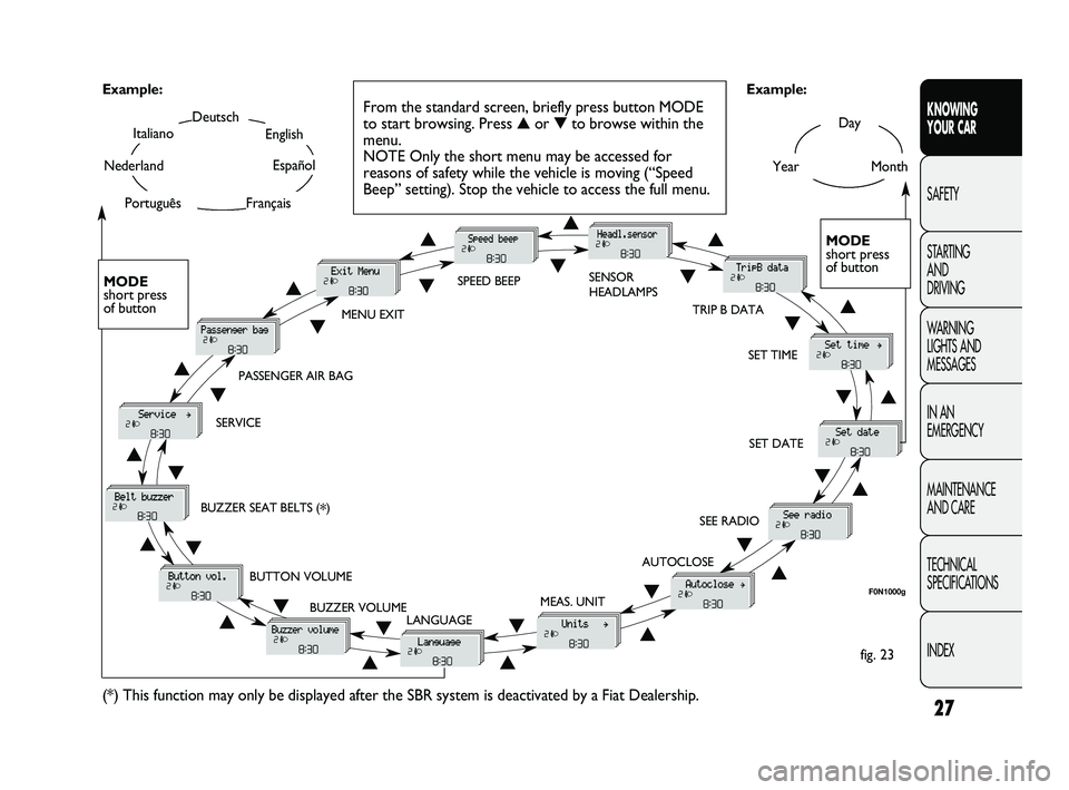
fig. 23 Example:
From the standard screen, briefly press button MODE
to start browsing. Press ▲or ▼to browse within the
menu.
NOTE Only the short menu may be accessed for
reasons of safety while the vehicle is moving (“Speed
Beep” setting). Stop the vehicle to access the full menu.
F0N1000g
MODE
short press
of button
▲
▼
MENU EXITSPEED BEEPSENSOR
HEADLAMPS
SET TIME
SET DATE
SEE RADIO
AUTOCLOSE
MEAS. UNIT
LANGUAGE BUZZER VOLUME BUTTON VOLUME BUZZER SEAT BELTS (
*) SERVICEPASSENGER AIR BAG
(*) This function may only be displayed after the SBR system is deactivated by a Fiat Dealership.
TRIP B DATA
MODE
short press
of button
▲
▼▲
▼▲
▼
▲
▼
▲ ▼
▲ ▼ ▲
▼
▲
▼
▲
▼
▲▼
▲▼
▲▼
▲▼▼
▲
001-036 DUCATO LUM EN 7ed 6/21/10 2:09 PM Page 27
Page 29 of 286
To cancel the setting, proceed as follows:
– briefly press button MODE: ON flashes on the display;
– press button
▼: OFF flashes on the display;
– press the MODE button briefly to return to the menu
screen or press the button for longer to return to the
standard screen without memorising.
Headlight sensor sensitivity adjustment
(for versions/markets where provided)
With this function it is possible to adjust the rain
headlight sensitivity according to 3 levels.
To set the required sensitivity level, proceed as follows:
– briefly press button MODE: the previously set
sensitivity “level” start to flash on the display;
– press button
▲or ▼to adjust;
– press the MODE button briefly to return to the menu
screen or press the button for longer to return to the
standard screen without memorising. Speed limit (Speed Beep)
This function enables setting of the vehicle speed limit
(km/h or mph). When this limit is exceeded the driver is
immediately alerted (see section “Warning lights and
messages”).
To set the desired speed limit, proceed as follows:
– briefly press button MODE: the display will show the
wording “Speed Beep”;
– press button
▲or ▼to activate (On) or deactivate
(Off) the speed limit;
– if the function has been activated (On), press buttons
▲or ▼to select the required speed limit and then
press MODE to confirm.
NOTE.
The speed may be set in the range from 30 to
200 km/h, or from 20 to 125 mph according to the
previously chosen unit (see “Setting the distance unit”
paragraph ) described below. The setting will increase/
decrease by five units each time button
▲/▼is pressed.
Hold down button
▲/▼to increase/decrease the setting
rapidly. Complete the setting by briefly pressing the
button when you approach the required value.
– press the MODE button briefly to return to the menu
screen or press the button for longer to return to the
standard screen without memorising.
28
KNOWING
YOUR CAR
SAFETY
STARTING
AND
DRIVING
WARNING
LIGHTS AND
MESSAGES
IN AN
EMERGENCY
MAINTENANCE
AND CARE
TECHNICAL
SPECIFICATIONS
INDEX
001-036 DUCATO LUM EN 7ed 6/21/10 2:09 PM Page 28
Page 61 of 286
60
KNOWING
YOUR CAR
SAFETY
STARTING
AND
DRIVING
WARNING
LIGHTS AND
MESSAGES
IN AN
EMERGENCY
MAINTENANCE
AND CARE
TECHNICAL
SPECIFICATIONS
INDEX
The intake air temperature is always automatically
controlled according to the temperature set on the display
(except for when the system is off or in certain conditions
when the compressor is not running).
The system allows the following parameters and
functions to be set or altered manually: air temperature,
fan speed (continuous variation); air distribution in
seven positions; compressor enablement, fast
defrosting/demisting
function; air recirculation; switching off of the system;
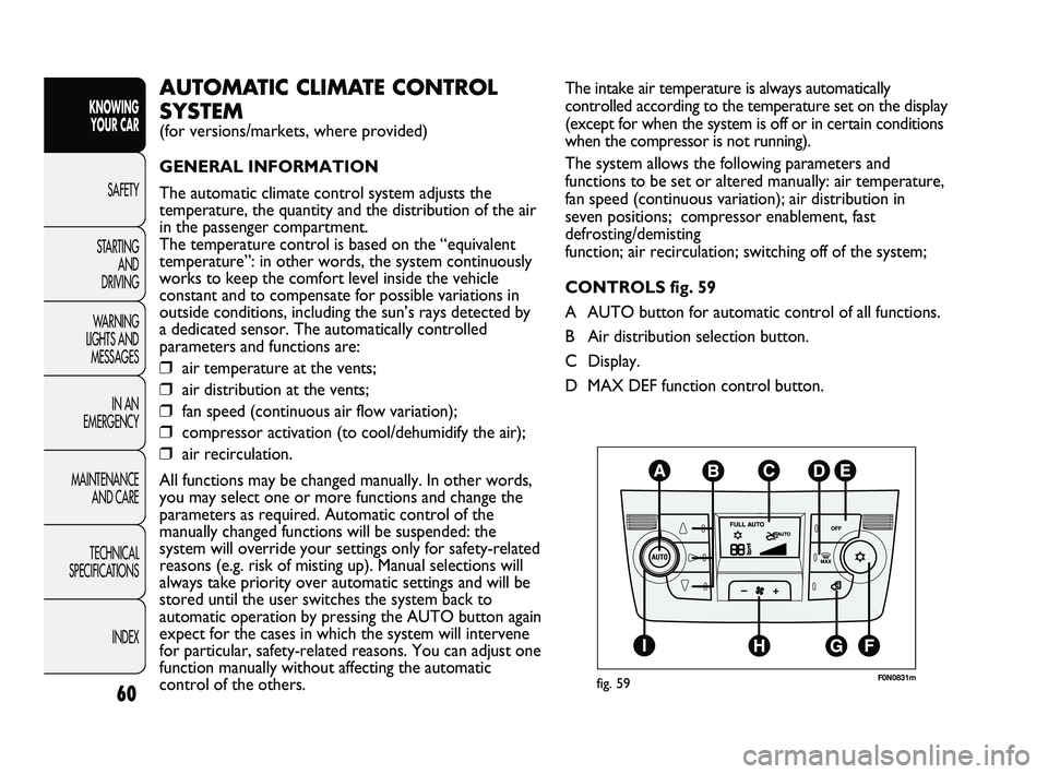
CONTROLS fig. 59
A AUTO button for automatic control of all functions.
B Air distribution selection button.
C Display.
D MAX DEF function control button.AUTOMATIC CLIMATE CONTROL
SYSTEM
(for versions/markets, where provided)
GENERAL INFORMATION
The automatic climate control system adjusts the
temperature, the quantity and the distribution of the air
in the passenger compartment.
The temperature control is based on the “equivalent
temperature”: in other words, the system continuously
works to keep the comfort level inside the vehicle
constant and to compensate for possible variations in
outside conditions, including the sun’s rays detected by
a dedicated sensor. The automatically controlled
parameters and functions are:
❒air temperature at the vents;
❒air distribution at the vents;
❒fan speed (continuous air flow variation);
❒compressor activation (to cool/dehumidify the air);
❒air recirculation.
All functions may be changed manually. In other words,
you may select one or more functions and change the
parameters as required. Automatic control of the
manually changed functions will be suspended: the
system will override your settings only for safety-related
reasons (e.g. risk of misting up). Manual selections will
always take priority over automatic settings and will be
stored until the user switches the system back to
automatic operation by pressing the AUTO button again
expect for the cases in which the system will intervene
for particular, safety-related reasons. You can adjust one
function manually without affecting the automatic
control of the others.
F0N0831mfig. 59
037-128 DUCATO LUM EN 7ed 6/21/10 2:10 PM Page 60
Page 77 of 286
76
KNOWING
YOUR CAR
SAFETY
STARTING
AND
DRIVING
WARNING
LIGHTS AND
MESSAGES
IN AN
EMERGENCY
MAINTENANCE
AND CARE
TECHNICAL
SPECIFICATIONS
INDEX
F0N0036mfig. 75
Each time the lever is operated the lights will stay on
another 30 seconds, up to a maximum of 210 seconds;
when this time has elapsed, the lights will go out
automatically.
The warning light 3on the instrument panel will light
up and the corresponding message will appear in the
display (see “Warning lights and messages”) for as long
as the function is activated. The warning light comes on
when the lever is operated and stays on until the
function is automatically deactivated. Each movement of
the lever only increases the amount of time the lights
stay on.
Deactivation
Keep the lever pulled towards the steering wheel for
more than 2 seconds.
AUTOMATIC HEADLIGHT SENSOR
(dusk sensor)
(for versions/markets, where provided)
It detects variations in brightness outside the vehicle
depending on the light sensitivity setting: the greater the
sensitivity, the less outside light needed to activate the
exterior lights being turned on. The sensitivity of the
dusk sensor is adjusted by means of the “Setup menu”
for the display. Lane change function
If you wish to signal a lane change, place the left lever in
the unstable position for less than half a second. The
direction indicator on the side selected will flash five
times and then switch off automatically.
“FOLLOW ME HOME” DEVICE
This device allows the illumination of the space in front
of the vehicle for a preset time.
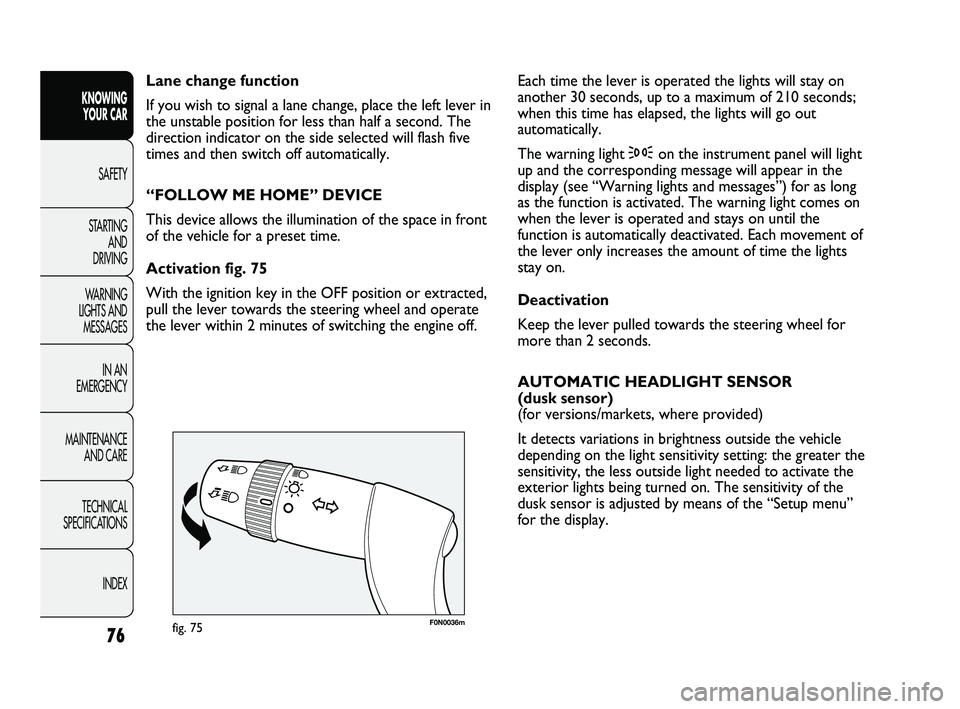
Activation fig. 75
With the ignition key in the OFF position or extracted,
pull the lever towards the steering wheel and operate
the lever within 2 minutes of switching the engine off.
037-128 DUCATO LUM EN 7ed 6/21/10 2:10 PM Page 76
Page 78 of 286
77
KNOWING
YOUR CAR
SAFETY
STARTING
AND
DRIVING
WARNING
LIGHTS AND
MESSAGES
IN AN
EMERGENCY
MAINTENANCE
AND CARE
TECHNICAL
SPECIFICATIONS
INDEX
F0N0037mfig. 76
WINDOW WASHING
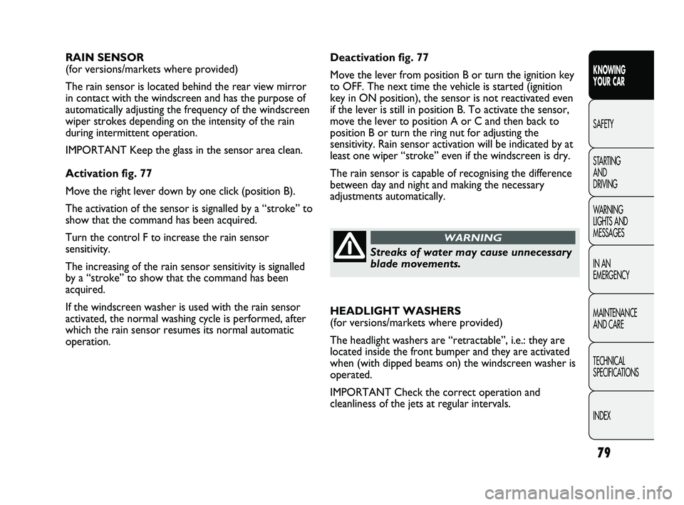
WINDSCREEN WASHER/WIPER
The device can operate only when the ignition key is in
the MAR-ON position. There are five different positions
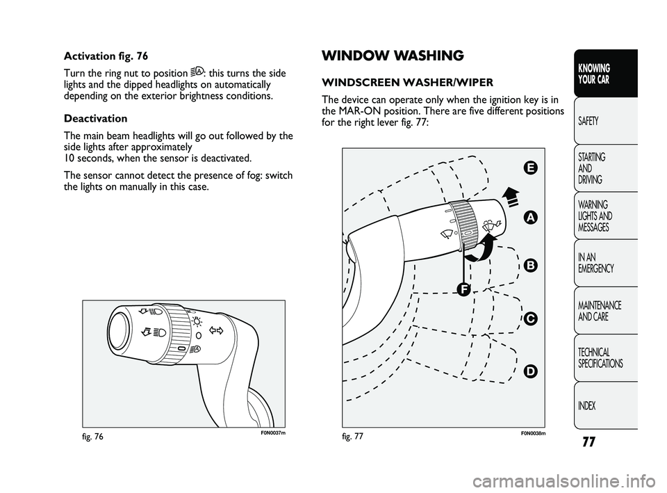
for the right lever fig. 77: Activation fig. 76
Turn the ring nut to position 2A: this turns the side
lights and the dipped headlights on automatically
depending on the exterior brightness conditions.
Deactivation
The main beam headlights will go out followed by the
side lights after approximately
10 seconds, when the sensor is deactivated.
The sensor cannot detect the presence of fog: switch
the lights on manually in this case.
fig. 77F0N0038m
037-128 DUCATO LUM EN 7ed 6/21/10 2:10 PM Page 77
Page 80 of 286
79
KNOWING
YOUR CAR
SAFETY
STARTING
AND
DRIVING
WARNING
LIGHTS AND
MESSAGES
IN AN
EMERGENCY
MAINTENANCE
AND CARE
TECHNICAL
SPECIFICATIONS
INDEX
Deactivation fig. 77
Move the lever from position B or turn the ignition key
to OFF. The next time the vehicle is started (ignition
key in ON position), the sensor is not reactivated even
if the lever is still in position B. To activate the sensor,
move the lever to position A or C and then back to
position B or turn the ring nut for adjusting the
sensitivity. Rain sensor activation will be indicated by at
least one wiper “stroke” even if the windscreen is dry.
The rain sensor is capable of recognising the difference
between day and night and making the necessary
adjustments automatically. RAIN SENSOR
(for versions/markets where provided)
The rain sensor is located behind the rear view mirror
in contact with the windscreen and has the purpose of
automatically adjusting the frequency of the windscreen
wiper strokes depending on the intensity of the rain
during intermittent operation.
IMPORTANT Keep the glass in the sensor area clean.
Activation fig. 77
Move the right lever down by one click (position B).
The activation of the sensor is signalled by a “stroke” to
show that the command has been acquired.
Turn the control F to increase the rain sensor
sensitivity.
The increasing of the rain sensor sensitivity is signalled
by a “stroke” to show that the command has been
acquired.
If the windscreen washer is used with the rain sensor
activated, the normal washing cycle is performed, after
which the rain sensor resumes its normal automatic
operation.HEADLIGHT WASHERS
(for versions/markets where provided)
The headlight washers are “retractable”, i.e.: they are
located inside the front bumper and they are activated
when (with dipped beams on) the windscreen washer is
operated.
IMPORTANT Check the correct operation and
cleanliness of the jets at regular intervals.
Streaks of water may cause unnecessary
blade movements.
WARNING
037-128 DUCATO LUM EN 7ed 6/21/10 2:10 PM Page 79
Page 122 of 286
121
KNOWING
YOUR CAR
SAFETY
STARTING
AND
DRIVING
WARNING
LIGHTS AND
MESSAGES
IN AN
EMERGENCY
MAINTENANCE
AND CARE
TECHNICAL
SPECIFICATIONS
INDEX
F0N0119mfig. 136
Detection distances
Central action range: 140 cm ±10 cm
Side action range: 60 cm ±20 cm
If several obstacles are detected by the sensors, only the
nearest one is considered.
FAILURE WARNING
Any parking sensor failures will be indicated when
engaging reverse by the
twarning light in the instrument
panel together with the message in the multifunction
display coming on for versions/markets where provided
(see “Warning lights and messages” section).
PARKING SENSORS
(for versions/markets where provided)
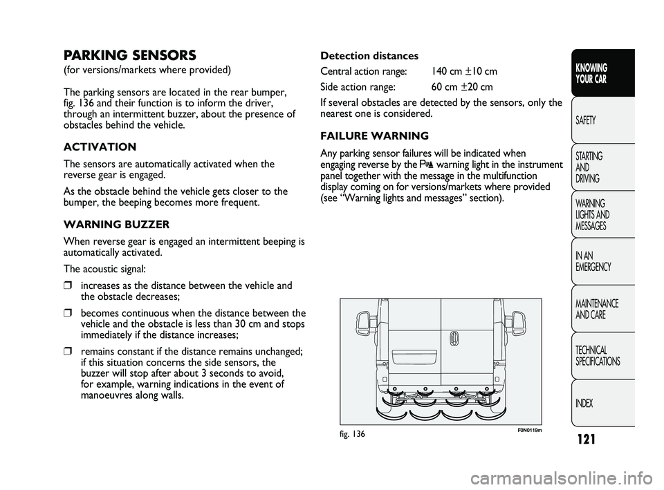
The parking sensors are located in the rear bumper,
fig. 136 and their function is to inform the driver,
through an intermittent buzzer, about the presence of
obstacles behind the vehicle.
ACTIVATION
The sensors are automatically activated when the
reverse gear is engaged.
As the obstacle behind the vehicle gets closer to the
bumper, the beeping becomes more frequent.
WARNING BUZZER
When reverse gear is engaged an intermittent beeping is
automatically activated.
The acoustic signal:
❒increases as the distance between the vehicle and
the obstacle decreases;
❒becomes continuous when the distance between the
vehicle and the obstacle is less than 30 cm and stops
immediately if the distance increases;
❒remains constant if the distance remains unchanged;
if this situation concerns the side sensors, the
buzzer will stop after about 3 seconds to avoid,
for example, warning indications in the event of
manoeuvres along walls.
037-128 DUCATO LUM EN 7ed 6/21/10 2:11 PM Page 121
Page 123 of 286
122
KNOWING
YOUR CAR
SAFETY
STARTING
AND
DRIVING
WARNING
LIGHTS AND
MESSAGES
IN AN
EMERGENCY
MAINTENANCE
AND CARE
TECHNICAL
SPECIFICATIONS
INDEX
OPERATION WITH TRAILER
Parking sensor operation is automatically disabled when
the electric cable plug of the trailer is fitted into the
vehicle tow hook socket.
The sensors are automatically enabled again when the
trailer cable plug is removed.
IMPORTANT If you wish to leave the tow hook fitted
without towing a trailer, it is advisable to contact a Fiat
Dealership for the relevant system update operations
because the tow hook could be detected as an obstacle
by the central sensors.
When using special washing equipment such as high
pressure jets or steam cleaning, clean the sensors very
quickly keeping the jet more than 10 cm away.
The driver always has ultimate
responsibility for parking and other
dangerous manoeuvres. While manoeuvring,
always make sure that no-one is in the area
concerned (especially children) or animals.
The parking sensors are designed to assist
drivers: in any case, you must always pay the
utmost attention during potentially dangerous
manoeuvres, even when carried out at low
speed.
WARNING
For correct operation, sensors must
always be clean from mud, dirt, snow or
ice. Be careful not to scratch or damage
the sensors while cleaning them. Avoid using dry,
rough or hard cloths. The sensors should be
washed with clean water, possibly with some car
shampoo.
GENERAL WARNINGS
❒When parking, take the utmost care over obstacles
that may be above or below the sensors.
❒Objects close to the vehicle, in certain
circumstances are not detected and could therefore
cause damage to the vehicle or be damaged.
The following conditions may influence the performance
of the parking sensor system:
❒Reduced sensor sensitivity and a reduction in the
parking assistance system performance could be due
to the presence on the surface of the sensor of: ice,
snow, mud, thick paint.
037-128 DUCATO LUM EN 7ed 6/21/10 2:11 PM Page 122
Page 124 of 286
123
KNOWING
YOUR CAR
SAFETY
STARTING
AND
DRIVING
WARNING
LIGHTS AND
MESSAGES
IN AN
EMERGENCY
MAINTENANCE
AND CARE
TECHNICAL
SPECIFICATIONS
INDEX
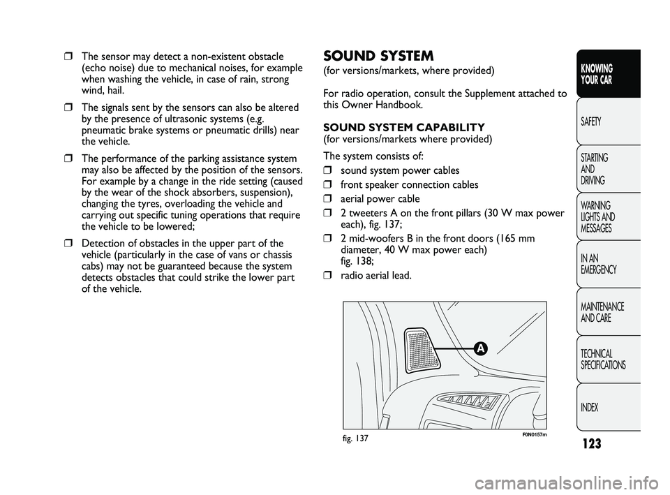
F0N0157mfig. 137
SOUND SYSTEM
(for versions/markets, where provided)
For radio operation, consult the Supplement attached to
this Owner Handbook.
SOUND SYSTEM CAPABILITY
(for versions/markets where provided)
The system consists of:
❒sound system power cables
❒front speaker connection cables
❒aerial power cable
❒2 tweeters A on the front pillars (30 W max power
each), fig. 137;
❒2 mid-woofers B in the front doors (165 mm
diameter, 40 W max power each)
fig. 138;
❒radio aerial lead.
❒The sensor may detect a non-existent obstacle
(echo noise) due to mechanical noises, for example
when washing the vehicle, in case of rain, strong
wind, hail.
❒The signals sent by the sensors can also be altered
by the presence of ultrasonic systems (e.g.
pneumatic brake systems or pneumatic drills) near
the vehicle.
❒The performance of the parking assistance system
may also be affected by the position of the sensors.
For example by a change in the ride setting (caused
by the wear of the shock absorbers, suspension),
changing the tyres, overloading the vehicle and
carrying out specific tuning operations that require
the vehicle to be lowered;
❒Detection of obstacles in the upper part of the
vehicle (particularly in the case of vans or chassis
cabs) may not be guaranteed because the system
detects obstacles that could strike the lower part
of the vehicle.
037-128 DUCATO LUM EN 7ed 6/21/10 2:11 PM Page 123