tow FIAT DUCATO 2010 Owner handbook (in English)
[x] Cancel search | Manufacturer: FIAT, Model Year: 2010, Model line: DUCATO, Model: FIAT DUCATO 2010Pages: 286, PDF Size: 12.53 MB
Page 11 of 286
IMPORTANT The engine lock function is guaranteed by
the Fiat CODE, which is automatically activated when
the ignition key is extracted from the starter device.
TURNING THE ALARM ON
With the doors and bonnet closed and the ignition key
either turned to STOP or removed, point the key with
the remote control towards the vehicle and press and
release the lock button.
Excluding some markets, the system produces an
acoustic warning (beep) and enables door locking.
The switching on of the alarm is preceded by an self-
diagnosis stage: if a fault is detected, the system
produces another acoustic signal.
In this case, turn the alarm off by pressing the “release
doors/release load compartment” button, check that the
doors and bonnet are properly closed and turn the
alarm back on by pressing the lock button.
If a door or the bonnet is not properly shut, it will be
excluded from the testing by the alarm system.
If the alarm produces an acoustic signal even when the
doors and bonnet are correctly closed, a fault has
occurred in the operation of the system. Contact a Fiat
Dealership.ELECTRONIC ALARM
(for versions/markets where provided)
The alarm, in addition to all the remote control
functions described previously, is controlled by the
receiver located under the dashboard near the fuse box.
ALARM TRIPPING
The alarm intervenes in the following cases:
❒when one of the doors or bonnet is opened
illegitimately (perimeter protection);
❒when the ignition system is started up (ignition key
rotated to MAR-ON);
❒when the battery cables are cut;
❒when the vehicle is lifted or tilted.
Depending on the market, the activation of the alarm
causes the activation of the siren and the direction
indicators (for about 26 seconds). Alarm tripping and
the number of cycles depend on the sales market.
There is a maximum number of acoustic/visual cycles.
When this is reached the system returns to normal
operation.
The antilift protection may be turned off by means of
the appropriate button (see “Antilift protection”
paragraph overleaf).
10
KNOWING
YOUR CAR
SAFETY
STARTING
AND
DRIVING
WARNING
LIGHTS AND
MESSAGES
IN AN
EMERGENCY
MAINTENANCE
AND CARE
TECHNICAL
SPECIFICATIONS
INDEX
001-036 DUCATO LUM EN 7ed 6/21/10 2:08 PM Page 10
Page 12 of 286
11
KNOWING
YOUR CAR
SAFETY
STARTING
AND
DRIVING
WARNING
LIGHTS AND
MESSAGES
IN AN
EMERGENCY
MAINTENANCE
AND CARE
TECHNICAL
SPECIFICATIONS
INDEX
F0N0232mfig. 9
ANTI-LIFT PROTECTION
The anti-lift protection system consists in a sensor
which detects any change in vehicle tilting with a view
to identifying any possible vehicle lifting, even partial
(e.g. when a tyre is removed).
The sensor also detects minor changes in the vehicle
angle both along the longitudinal and transverse axis.
Disabling the anti-lift protection
The anti-lift protection is disabled (for instance when
the vehicle needs to be towed with the alarm engaged)
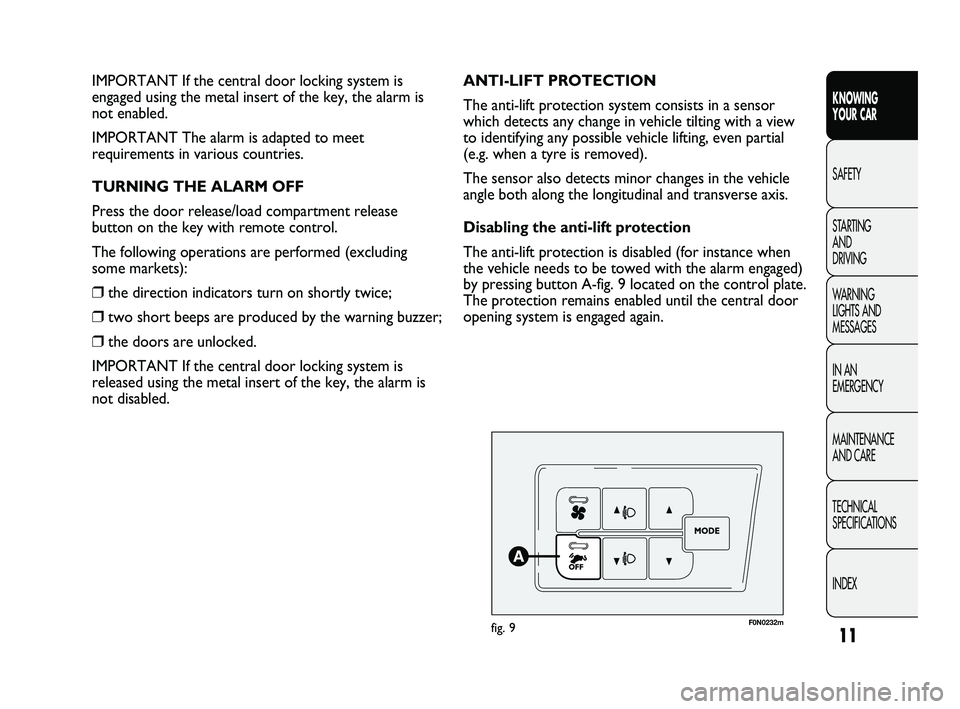
by pressing button A-fig. 9 located on the control plate.
The protection remains enabled until the central door
opening system is engaged again. IMPORTANT If the central door locking system is
engaged using the metal insert of the key, the alarm is
not enabled.
IMPORTANT The alarm is adapted to meet
requirements in various countries.
TURNING THE ALARM OFF
Press the door release/load compartment release
button on the key with remote control.
The following operations are performed (excluding
some markets):
❒the direction indicators turn on shortly twice;
❒two short beeps are produced by the warning buzzer;
❒the doors are unlocked.
IMPORTANT If the central door locking system is
released using the metal insert of the key, the alarm is
not disabled.
001-036 DUCATO LUM EN 7ed 6/21/10 2:08 PM Page 11
Page 14 of 286
13
KNOWING
YOUR CAR
SAFETY
STARTING
AND
DRIVING
WARNING
LIGHTS AND
MESSAGES
IN AN
EMERGENCY
MAINTENANCE
AND CARE
TECHNICAL
SPECIFICATIONS
INDEX
Never extract the key while the vehicle
is moving. The steering wheel would
automatically lock as soon as you try to turn it.
This is always the case, even when the vehicle is
being towed.
WARNING
It is absolutely forbidden to carry out
any after-sales operation involving
steering system or steering column
modifications (e.g. installing an anti-theft
device) that could badly affect performance and
safety, invalidate the warranty and also result in
the vehicle failing to comply with regulations.
WARNING
If the ignition device is tampered with
(e.g.: attempted theft), have it checked
over by a Fiat Dealership as soon as possible.
WARNING
Always remove the key from the vehicle
when leaving it in order to prevent
accidental engagement of the control.
Remember to engage the handbrake. Engage
first gear if the vehicle is parked uphill or
reverse gear if the vehicle is parked downhill.
Never leave children unattended in the vehicle.
WARNING
STEERING LOCK
Engagement
When the key is at STOP, remove the key and turn the
steering wheel until it locks.
Disengagement
Move the steering wheel slightly as you turn the ignition
key to MAR-ON.
001-036 DUCATO LUM EN 7ed 6/21/10 2:08 PM Page 13
Page 40 of 286
39
KNOWING
YOUR CAR
SAFETY
STARTING
AND
DRIVING
WARNING
LIGHTS AND
MESSAGES
IN AN
EMERGENCY
MAINTENANCE
AND CARE
TECHNICAL
SPECIFICATIONS
INDEX
F0N0148mfig. 29
12
F0N0187mfig. 31
F0N0187mfig. 30
REVOLVING BASE SEAT
(for versions/markets where provided)
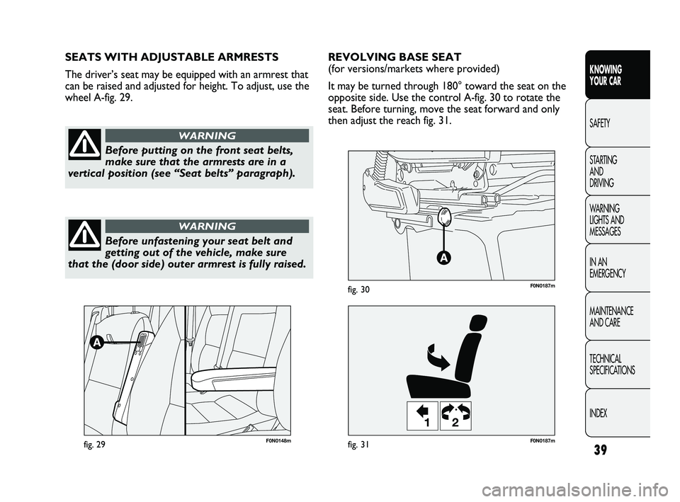
It may be turned through 180° toward the seat on the
opposite side. Use the control A-fig. 30 to rotate the
seat. Before turning, move the seat forward and only
then adjust the reach fig. 31. SEATS WITH ADJUSTABLE ARMRESTS
The driver’s seat may be equipped with an armrest that
can be raised and adjusted for height. To adjust, use the
wheel A-fig. 29.
Before putting on the front seat belts,
make sure that the armrests are in a
vertical position (see “Seat belts” paragraph).
WARNING
Before unfastening your seat belt and
getting out of the vehicle, make sure
that the (door side) outer armrest is fully raised.
WARNING
037-128 DUCATO LUM EN 7ed 6/21/10 2:10 PM Page 39
Page 41 of 286
40
KNOWING
YOUR CAR
SAFETY
STARTING
AND
DRIVING
WARNING
LIGHTS AND
MESSAGES
IN AN
EMERGENCY
MAINTENANCE
AND CARE
TECHNICAL
SPECIFICATIONS
INDEX
F0N0173mfig. 32F0N0174mfig. 33
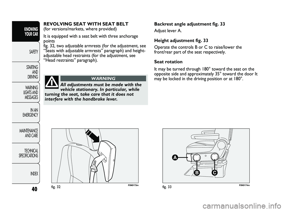
Backrest angle adjustment fig. 33
Adjust lever A.
Height adjustment fig. 33
Operate the controls B or C to raise/lower the
front/rear part of the seat respectively.
Seat rotation
It may be turned through 180° toward the seat on the
opposite side and approximately 35° toward the door It
may be locked in the driving position or at 180°. REVOLVING SEAT WITH SEAT BELT
(for versions/markets, where provided)
It is equipped with a seat belt with three anchorage
points
fig. 32, two adjustable armrests (for the adjustment, see
“Seats with adjustable armrests” paragraph) and height-
adjustable head restraints (for the adjustment, see
“Head restraints” paragraph).
All adjustments must be made with the
vehicle stationary. In particular, while
turning the seat, take care that it does not
interfere with the handbrake lever.
WARNING
037-128 DUCATO LUM EN 7ed 6/21/10 2:10 PM Page 40
Page 44 of 286
43
KNOWING
YOUR CAR
SAFETY
STARTING
AND
DRIVING
WARNING
LIGHTS AND
MESSAGES
IN AN
EMERGENCY
MAINTENANCE
AND CARE
TECHNICAL
SPECIFICATIONS
INDEX
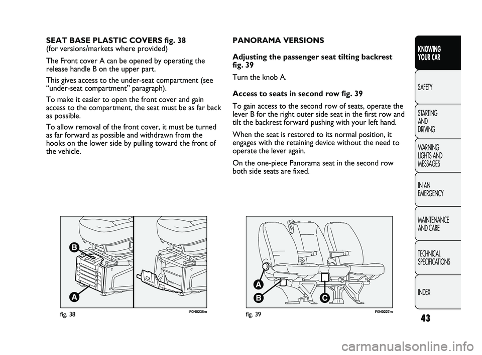
F0N0238mfig. 38
SEAT BASE PLASTIC COVERS fig. 38
(for versions/markets where provided)
The Front cover A can be opened by operating the
release handle B on the upper part.
This gives access to the under-seat compartment (see
“under-seat compartment” paragraph).
To make it easier to open the front cover and gain
access to the compartment, the seat must be as far back
as possible.
To allow removal of the front cover, it must be turned
as far forward as possible and withdrawn from the
hooks on the lower side by pulling toward the front of
the vehicle.
F0N0227mfig. 39
PANORAMA VERSIONS
Adjusting the passenger seat tilting backrest
fig. 39
Turn the knob A.
Access to seats in second row fig. 39
To gain access to the second row of seats, operate the
lever B for the right outer side seat in the first row and
tilt the backrest forward pushing with your left hand.
When the seat is restored to its normal position, it
engages with the retaining device without the need to
operate the lever again.
On the one-piece Panorama seat in the second row
both side seats are fixed.
037-128 DUCATO LUM EN 7ed 6/21/10 2:10 PM Page 43
Page 48 of 286
47
KNOWING
YOUR CAR
SAFETY
STARTING
AND
DRIVING
WARNING
LIGHTS AND
MESSAGES
IN AN
EMERGENCY
MAINTENANCE
AND CARE
TECHNICAL
SPECIFICATIONS
INDEX
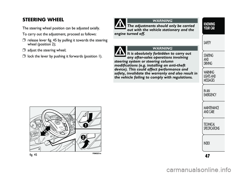
F0N0321mfig. 45
STEERING WHEEL
The steering wheel position can be adjusted axially.
To carry out the adjustment, proceed as follows:
❒release lever fig. 45 by pulling it towards the steering
wheel (position 2);
❒adjust the steering wheel;
❒lock the lever by pushing it forwards (position 1).
The adjustments should only be carried
out with the vehicle stationary and the
engine turned off.
WARNING
It is absolutely forbidden to carry out
any after-sales operations involving
steering system or steering column
modifications (e.g. installing an anti-theft
device). This could affect performance and
safety, invalidate the warranty and also result in
the vehicle failing to comply with regulations.
WARNING
037-128 DUCATO LUM EN 7ed 6/21/10 2:10 PM Page 47
Page 75 of 286
74
KNOWING
YOUR CAR
SAFETY
STARTING
AND
DRIVING
WARNING
LIGHTS AND
MESSAGES
IN AN
EMERGENCY
MAINTENANCE
AND CARE
TECHNICAL
SPECIFICATIONS
INDEX
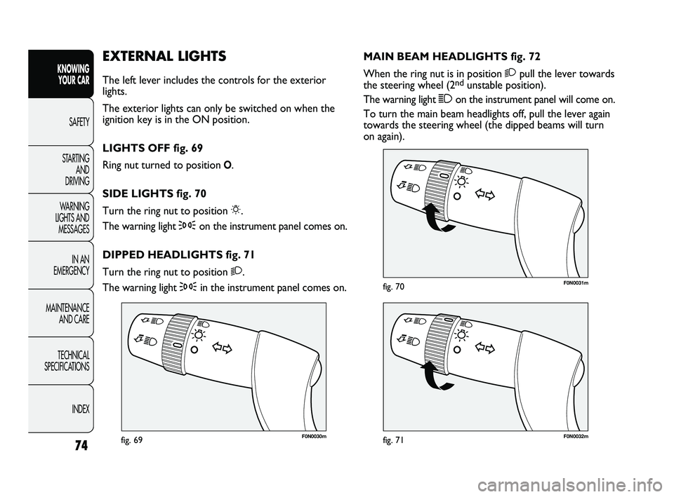
F0N0030mfig. 69F0N0032mfig. 71
F0N0031mfig. 70
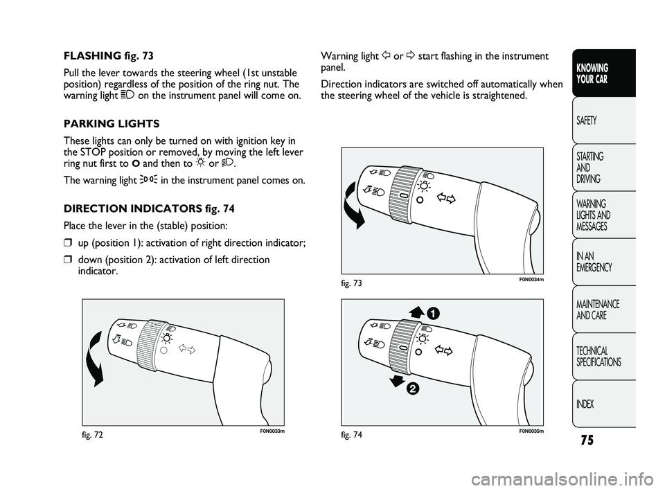
MAIN BEAM HEADLIGHTS fig. 72
When the ring nut is in position 2pull the lever towards
the steering wheel (2
ndunstable position).
The warning light 1on the instrument panel will come on.
To turn the main beam headlights off, pull the lever again
towards the steering wheel (the dipped beams will turn
on again).
EXTERNAL LIGHTS
The left lever includes the controls for the exterior
lights.
The exterior lights can only be switched on when the
ignition key is in the ON position.
LIGHTS OFF fig. 69
Ring nut turned to position
O.
SIDE LIGHTS fig. 70
Turn the ring nut to position 6.
The warning light 3on the instrument panel comes on.
DIPPED HEADLIGHTS fig. 71
Turn the ring nut to position 2.
The warning light 3in the instrument panel comes on.
037-128 DUCATO LUM EN 7ed 6/21/10 2:10 PM Page 74
Page 76 of 286
75
KNOWING
YOUR CAR
SAFETY
STARTING
AND
DRIVING
WARNING
LIGHTS AND
MESSAGES
IN AN
EMERGENCY
MAINTENANCE
AND CARE
TECHNICAL
SPECIFICATIONS
INDEX
F0N0033mfig. 72
F0N0034mfig. 73
Warning light For Dstart flashing in the instrument
panel.
Direction indicators are switched off automatically when
the steering wheel of the vehicle is straightened. FLASHING fig. 73
Pull the lever towards the steering wheel (1st unstable
position) regardless of the position of the ring nut. The
warning light 1on the instrument panel will come on.
PARKING LIGHTS
These lights can only be turned on with ignition key in
the STOP position or removed, by moving the left lever
ring nut first to
Oand then to 6or 2.
The warning light
3in the instrument panel comes on.
DIRECTION INDICATORS fig. 74
Place the lever in the (stable) position:
❒up (position 1): activation of right direction indicator;
❒down (position 2): activation of left direction
indicator.
F0N0035mfig. 74
037-128 DUCATO LUM EN 7ed 6/21/10 2:10 PM Page 75
Page 77 of 286
76
KNOWING
YOUR CAR
SAFETY
STARTING
AND
DRIVING
WARNING
LIGHTS AND
MESSAGES
IN AN
EMERGENCY
MAINTENANCE
AND CARE
TECHNICAL
SPECIFICATIONS
INDEX
F0N0036mfig. 75
Each time the lever is operated the lights will stay on
another 30 seconds, up to a maximum of 210 seconds;
when this time has elapsed, the lights will go out
automatically.
The warning light 3on the instrument panel will light
up and the corresponding message will appear in the
display (see “Warning lights and messages”) for as long
as the function is activated. The warning light comes on
when the lever is operated and stays on until the
function is automatically deactivated. Each movement of
the lever only increases the amount of time the lights
stay on.
Deactivation
Keep the lever pulled towards the steering wheel for
more than 2 seconds.
AUTOMATIC HEADLIGHT SENSOR
(dusk sensor)
(for versions/markets, where provided)
It detects variations in brightness outside the vehicle
depending on the light sensitivity setting: the greater the
sensitivity, the less outside light needed to activate the
exterior lights being turned on. The sensitivity of the
dusk sensor is adjusted by means of the “Setup menu”
for the display. Lane change function
If you wish to signal a lane change, place the left lever in
the unstable position for less than half a second. The
direction indicator on the side selected will flash five
times and then switch off automatically.
“FOLLOW ME HOME” DEVICE
This device allows the illumination of the space in front
of the vehicle for a preset time.
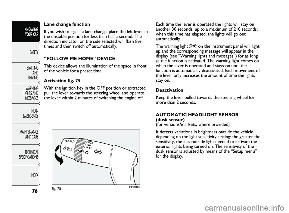
Activation fig. 75
With the ignition key in the OFF position or extracted,
pull the lever towards the steering wheel and operate
the lever within 2 minutes of switching the engine off.
037-128 DUCATO LUM EN 7ed 6/21/10 2:10 PM Page 76