technical specifications FIAT DUCATO 2012 Owner handbook (in English)
[x] Cancel search | Manufacturer: FIAT, Model Year: 2012, Model line: DUCATO, Model: FIAT DUCATO 2012Pages: 287, PDF Size: 4.5 MB
Page 178 of 287
174
KNOWING
YOUR CAR
SAFETY
STARTING
AND
DRIVING
WARNING
LIGHTS AND
MESSAGES
IN AN
EMERGENCY
MAINTENANCE
AND CARE
TECHNICAL
SPECIFICATIONS
INDEX
F0N0370mfig. 164F0N0168mfig. 166
F0N0167mfig. 165
âintroduce the supplied wrench C-fig. 162 with the
suitable extension B-fig. 161 on the screw A-fig. 161
of the spare wheel housing manoeuvring device and
turn clockwise 2 to lift the spare wheel back up until
it is fully supported in its housing beneath the floor
pan, checking that the attachment reference
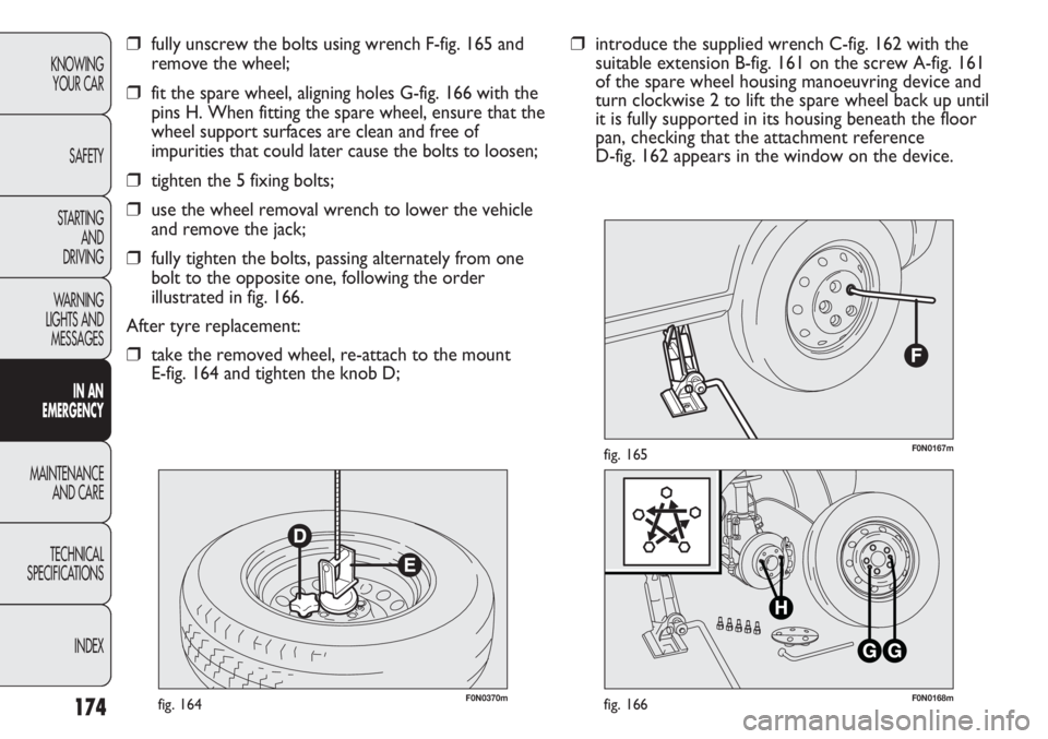
D-fig. 162 appears in the window on the device.âfully unscrew the bolts using wrench F-fig. 165 and
remove the wheel;
âfit the spare wheel, aligning holes G-fig. 166 with the
pins H. When fitting the spare wheel, ensure that the
wheel support surfaces are clean and free of
impurities that could later cause the bolts to loosen;
âtighten the 5 fixing bolts;
âuse the wheel removal wrench to lower the vehicle
and remove the jack;
âfully tighten the bolts, passing alternately from one
bolt to the opposite one, following the order
illustrated in fig. 166.
After tyre replacement:
âtake the removed wheel, re-attach to the mount
E-fig. 164 and tighten the knob D;
Page 179 of 287
175
KNOWING
YOUR CAR
SAFETY
STARTING
AND
DRIVING
WARNING
LIGHTS AND
MESSAGES
IN AN
EMERGENCY
MAINTENANCE
AND CARE
TECHNICAL
SPECIFICATIONS
INDEX
F0N0251mfig. 168
F0N0837mfig. 167
For vehicles with alloy rims, proceed as follows:
âtake the kit from the tool box;
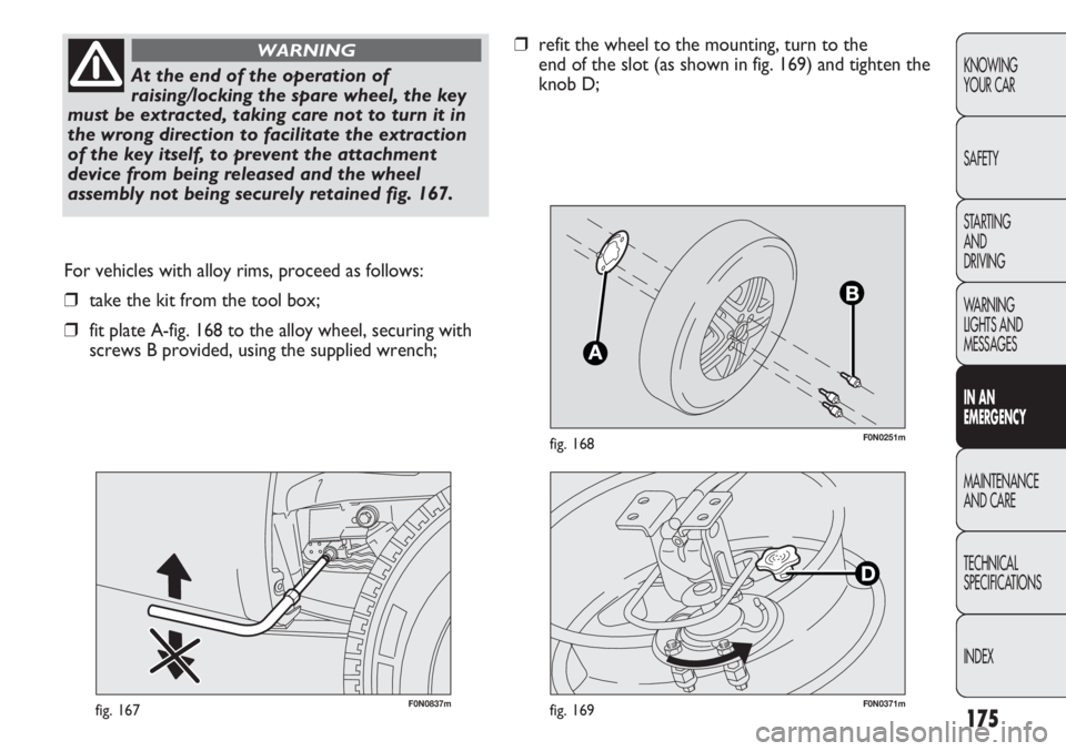
âfit plate A-fig. 168 to the alloy wheel, securing with
screws B provided, using the supplied wrench;
At the end of the operation of
raising/locking the spare wheel, the key
must be extracted, taking care not to turn it in
the wrong direction to facilitate the extraction
of the key itself, to prevent the attachment
device from being released and the wheel
assembly not being securely retained fig. 167.
WARNINGârefit the wheel to the mounting, turn to the
end of the slot (as shown in fig. 169) and tighten the
knob D;
F0N0371mfig. 169
Page 180 of 287
176
KNOWING
YOUR CAR
SAFETY
STARTING
AND
DRIVING
WARNING
LIGHTS AND
MESSAGES
IN AN
EMERGENCY
MAINTENANCE
AND CARE
TECHNICAL
SPECIFICATIONS
INDEX
E
F0N0825mfig. 170
Automatic FIX&GO QUICK TYRE
REPAIR KIT
(for versions/markets where provided)
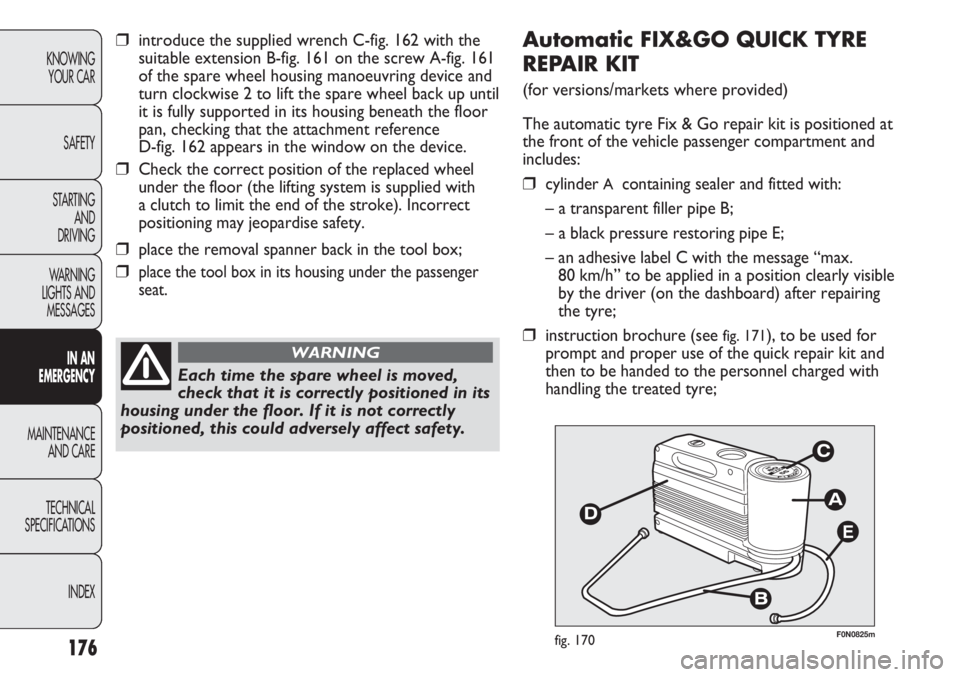
The automatic tyre Fix & Go repair kit is positioned at
the front of the vehicle passenger compartment and
includes:
âcylinder A containing sealer and fitted with:
â a transparent filler pipe B;
â a black pressure restoring pipe E;
â an adhesive label C with the message âmax.
80 km/hâ to be applied in a position clearly visible
by the driver (on the dashboard) after repairing
the tyre;
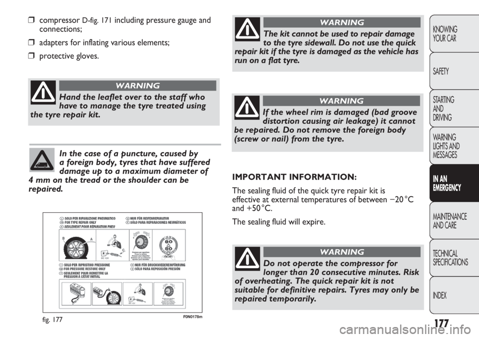
âinstruction brochure (see fig. 171), to be used for
prompt and proper use of the quick repair kit and
then to be handed to the personnel charged with
handling the treated tyre;
Each time the spare wheel is moved,
check that it is correctly positioned in its
housing under the floor. If it is not correctly
positioned, this could adversely affect safety.
WARNING
âintroduce the supplied wrench C-fig. 162 with the
suitable extension B-fig. 161 on the screw A-fig. 161
of the spare wheel housing manoeuvring device and
turn clockwise 2 to lift the spare wheel back up until
it is fully supported in its housing beneath the floor
pan, checking that the attachment reference
D-fig. 162 appears in the window on the device.
âCheck the correct position of the replaced wheel
under the floor (the lifting system is supplied with
a clutch to limit the end of the stroke). Incorrect
positioning may jeopardise safety.
âplace the removal spanner back in the tool box;
âplace the tool box in its housing under the passenger
seat.
Page 181 of 287
177
KNOWING
YOUR CAR
SAFETY
STARTING
AND
DRIVING
WARNING
LIGHTS AND
MESSAGES
IN AN
EMERGENCY
MAINTENANCE
AND CARE
TECHNICAL
SPECIFICATIONS
INDEX
F0N0178mfig. 177
âcompressor D-fig. 171including pressure gauge and
connections;
âadapters for inflating various elements;
âprotective gloves.
Hand the leaflet over to the staff who
have to manage the tyre treated using
the tyre repair kit.
WARNING
In the case of a puncture, caused by
a foreign body, tyres that have suffered
damage up to a maximum diameter of
4 mm on the tread or the shoulder can be
repaired.
The kit cannot be used to repair damage
to the tyre sidewall. Do not use the quick
repair kit if the tyre is damaged as the vehicle has
run on a flat tyre.
WARNING
If the wheel rim is damaged (bad groove
distortion causing air leakage) it cannot
be repaired. Do not remove the foreign body
(screw or nail) from the tyre.
WARNING
IMPORTANT INFORMATION:
The sealing fluid of the quick tyre repair kit is
effective at external temperatures of between â20 °C
and +50 °C.
The sealing fluid will expire.
Do not operate the compressor for
longer than 20 consecutive minutes. Risk
of overheating. The quick repair kit is not
suitable for definitive repairs. Tyres may only be
repaired temporarily.
WARNING
Page 182 of 287
178
KNOWING
YOUR CAR
SAFETY
STARTING
AND
DRIVING
WARNING
LIGHTS AND
MESSAGES
IN AN
EMERGENCY
MAINTENANCE
AND CARE
TECHNICAL
SPECIFICATIONS
INDEX
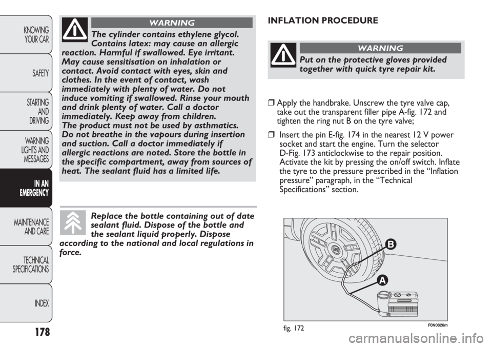
F0N0826mfig. 172
INFLATION PROCEDURE
The cylinder contains ethylene glycol.
Contains latex: may cause an allergic
reaction. Harmful if swallowed. Eye irritant.
May cause sensitisation on inhalation or
contact. Avoid contact with eyes, skin and
clothes. In the event of contact, wash
immediately with plenty of water. Do not
induce vomiting if swallowed. Rinse your mouth
and drink plenty of water. Call a doctor
immediately. Keep away from children.
The product must not be used by asthmatics.
Do not breathe in the vapours during insertion
and suction. Call a doctor immediately if
allergic reactions are noted. Store the bottle in
the specific compartment, away from sources of
heat. The sealant fluid has a limited life.
WARNING
Replace the bottle containing out of date
sealant fluid. Dispose of the bottle and
the sealant liquid properly. Dispose
according to the national and local regulations in
force.
Put on the protective gloves provided
together with quick tyre repair kit.
WARNING
âApply the handbrake. Unscrew the tyre valve cap,
take out the transparent filler pipe A-fig. 172 and
tighten the ring nut B on the tyre valve;
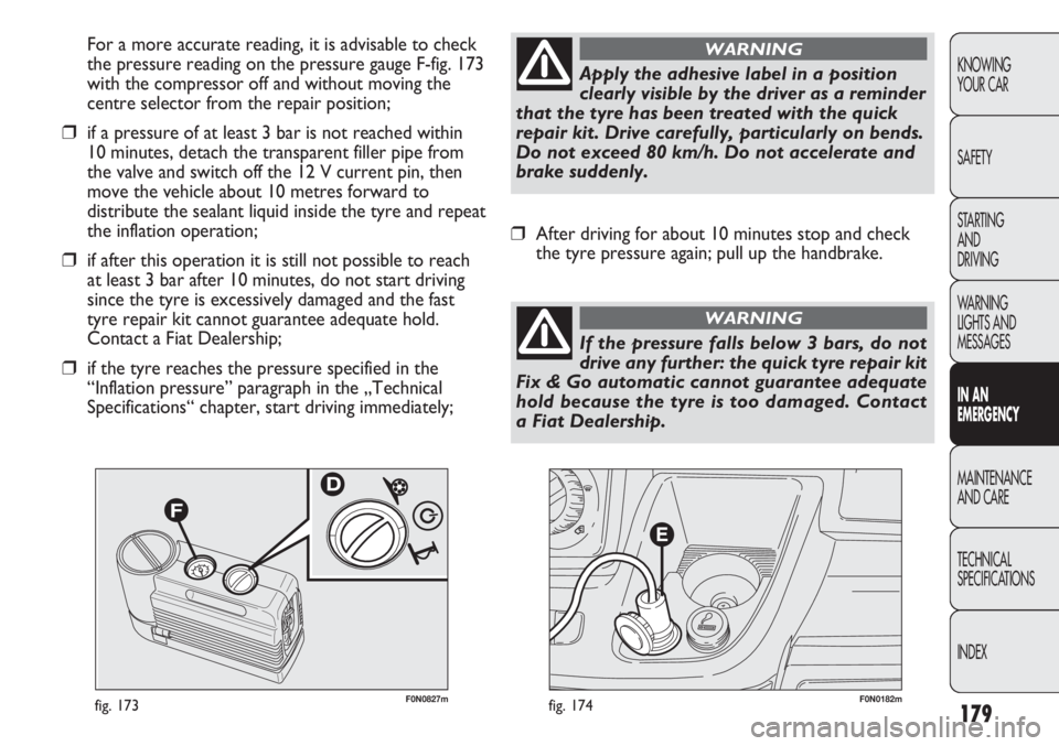
âInsert the pin E-fig. 174 in the nearest 12 V power
socket and start the engine. Turn the selector
D-Fig. 173 anticlockwise to the repair position.
Activate the kit by pressing the on/off switch. Inflate
the tyre to the pressure prescribed in the âInflation
pressureâ paragraph, in the âTechnical
Specificationsâ section.
Page 183 of 287
179
KNOWING
YOUR CAR
SAFETY
STARTING
AND
DRIVING
WARNING
LIGHTS AND
MESSAGES
IN AN
EMERGENCY
MAINTENANCE
AND CARE
TECHNICAL
SPECIFICATIONS
INDEX
F0N0182mfig. 174F0N0827mfig. 173
For a more accurate reading, it is advisable to check
the pressure reading on the pressure gauge F-fig. 173
with the compressor off and without moving the
centre selector from the repair position;
âif a pressure of at least 3 bar is not reached within
10 minutes, detach the transparent filler pipe from
the valve and switch off the 12 V current pin, then
move the vehicle about 10 metres forward to
distribute the sealant liquid inside the tyre and repeat
the inflation operation;
âif after this operation it is still not possible to reach
at least 3 bar after 10 minutes, do not start driving
since the tyre is excessively damaged and the fast
tyre repair kit cannot guarantee adequate hold.
Contact a Fiat Dealership;
âif the tyre reaches the pressure specified in the
âInflation pressureâ paragraph in the âTechnical
Specificationsâ chapter, start driving immediately;
Apply the adhesive label in a position
clearly visible by the driver as a reminder
that the tyre has been treated with the quick
repair kit. Drive carefully, particularly on bends.
Do not exceed 80 km/h. Do not accelerate and
brake suddenly.
WARNING
âAfter driving for about 10 minutes stop and check
the tyre pressure again; pull up the handbrake.
If the pressure falls below 3 bars, do not
drive any further: the quick tyre repair kit
Fix & Go automatic cannot guarantee adequate
hold because the tyre is too damaged. Contact
a Fiat Dealership.
WARNING
Page 184 of 287
180
KNOWING
YOUR CAR
SAFETY
STARTING
AND
DRIVING
WARNING
LIGHTS AND
MESSAGES
IN AN
EMERGENCY
MAINTENANCE
AND CARE
TECHNICAL
SPECIFICATIONS
INDEX
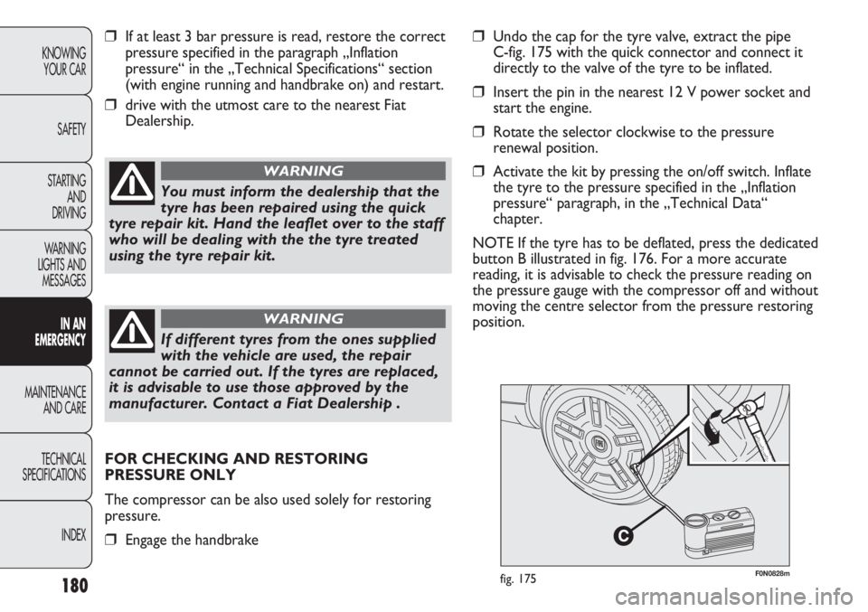
F0N0828mfig. 175
âIf at least 3 bar pressure is read, restore the correct
pressure specified in the paragraph âInflation
pressureâ in the âTechnical Specificationsâ section
(with engine running and handbrake on) and restart.
âdrive with the utmost care to the nearest Fiat
Dealership.
You must inform the dealership that the
tyre has been repaired using the quick
tyre repair kit. Hand the leaflet over to the staff
who will be dealing with the the tyre treated
using the tyre repair kit.
WARNING
If different tyres from the ones supplied
with the vehicle are used, the repair
cannot be carried out. If the tyres are replaced,
it is advisable to use those approved by the
manufacturer. Contact a Fiat Dealership .
WARNING
âUndo the cap for the tyre valve, extract the pipe
C-fig. 175 with the quick connector and connect it
directly to the valve of the tyre to be inflated.
âInsert the pin in the nearest 12 V power socket and
start the engine.
âRotate the selector clockwise to the pressure
renewal position.
âActivate the kit by pressing the on/off switch. Inflate
the tyre to the pressure specified in the âInflation
pressureâ paragraph, in the âTechnical Dataâ
chapter.
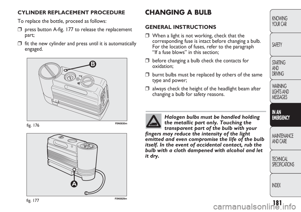
NOTE If the tyre has to be deflated, press the dedicated
button B illustrated in fig. 176. For a more accurate
reading, it is advisable to check the pressure reading on
the pressure gauge with the compressor off and without
moving the centre selector from the pressure restoring
position.
FOR CHECKING AND RESTORING
PRESSURE ONLY
The compressor can be also used solely for restoring
pressure.
âEngage the handbrake
Page 185 of 287
181
KNOWING
YOUR CAR
SAFETY
STARTING
AND
DRIVING
WARNING
LIGHTS AND
MESSAGES
IN AN
EMERGENCY
MAINTENANCE
AND CARE
TECHNICAL
SPECIFICATIONS
INDEX
B
F0N0830mfig. 176
F0N0829mfig. 177
CHANGING A BULB
GENERAL INSTRUCTIONS
âWhen a light is not working, check that the
corresponding fuse is intact before changing a bulb.
For the location of fuses, refer to the paragraph
âIf a fuse blowsâ in this section;
âbefore changing a bulb check the contacts for
oxidation;
âburnt bulbs must be replaced by others of the same
type and power;
âalways check the height of the headlight beam after
changing a bulb for safety reasons. CYLINDER REPLACEMENT PROCEDURE
To replace the bottle, proceed as follows:
âpress button A-fig. 177 to release the replacement
part;
âfit the new cylinder and press until it is automatically
engaged.
Halogen bulbs must be handled holding
the metallic part only. Touching the
transparent part of the bulb with your
fingers may reduce the intensity of the light
emitted and even compromise the life of the bulb
itself. In the event of accidental contact, rub the
bulb with a cloth dampened with alcohol and let
it dry.
Page 186 of 287
182
KNOWING
YOUR CAR
SAFETY
STARTING
AND
DRIVING
WARNING
LIGHTS AND
MESSAGES
IN AN
EMERGENCY
MAINTENANCE
AND CARE
TECHNICAL
SPECIFICATIONS
INDEX
F0N0078mfig. 178
Changes or repairs to the electrical
system (electric control units) carried
out incorrectly and without due consideration
for the technical specifications of the system
can lead to malfunctioning and generate a fire
hazard.
WARNING
Halogen lamps contain gas under
pressure. Their breaking can cause
scattering of glass fragments.
WARNING
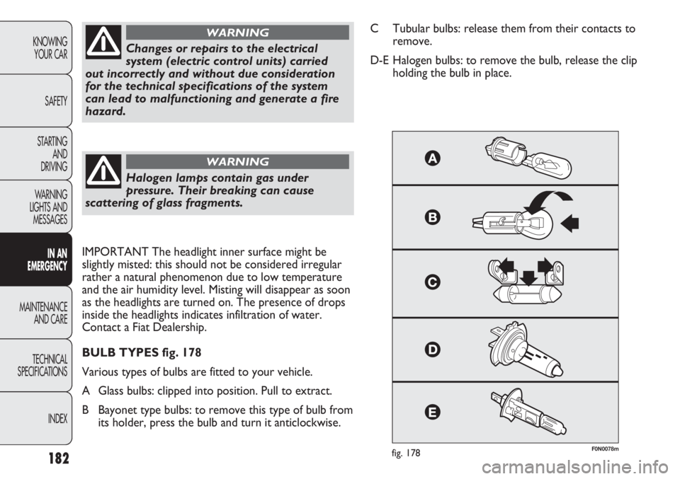
C Tubular bulbs: release them from their contacts to
remove.
D-E Halogen bulbs: to remove the bulb, release the clip
holding the bulb in place.
IMPORTANT The headlight inner surface might be
slightly misted: this should not be considered irregular
rather a natural phenomenon due to low temperature
and the air humidity level. Misting will disappear as soon
as the headlights are turned on. The presence of drops
inside the headlights indicates infiltration of water.
Contact a Fiat Dealership.
BULB TYPES fig. 178
Various types of bulbs are fitted to your vehicle.
A Glass bulbs: clipped into position. Pull to extract.
B Bayonet type bulbs: to remove this type of bulb from
its holder, press the bulb and turn it anticlockwise.
Page 187 of 287
183
KNOWING
YOUR CAR
SAFETY
STARTING
AND
DRIVING
WARNING
LIGHTS AND
MESSAGES
IN AN
EMERGENCY
MAINTENANCE
AND CARE
TECHNICAL
SPECIFICATIONS
INDEX
H1
H15
H7
W5W
H1
PY21W
W16WF(*)/WY5W(â¼)
PY21W
W5W
P21/5W
P21/5W
P21W
P21W
P21W
P21W
C5W
12V10W
12V10WD
D
D
A
â
B
A
B
A
B
B
B
â
â
â
A
C
C55W
15/55W
55W
5W
55W
21W
16W(*)/5W(â¼)
21W
5W
5W
5W
21W
21W
21W
21W
5W
10W
10W
(*) XL and recreational versions
(â¼) all other versions
(â) (for versions/markets where provided)
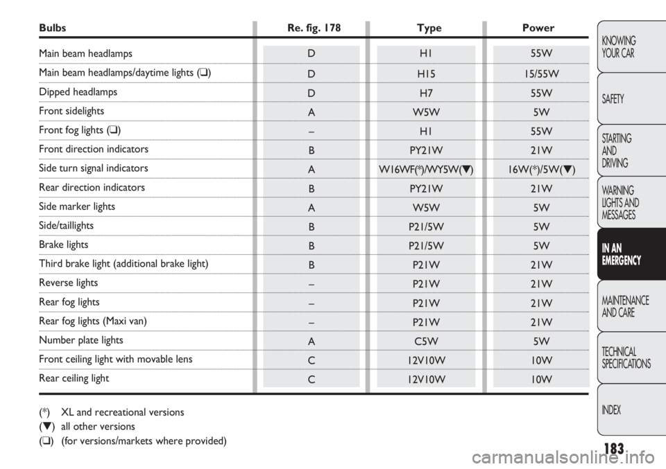
Bulbs Re. fig. 178 Type Power
Main beam headlamps
Main beam headlamps/daytime lights (â)
Dipped headlamps
Front sidelights
Front fog lights (â)
Front direction indicators
Side turn signal indicators
Rear direction indicators
Side marker lights
Side/taillights
Brake lights
Third brake light (additional brake light)
Reverse lights
Rear fog lights
Rear fog lights (Maxi van)
Number plate lights
Front ceiling light with movable lens
Rear ceiling light