technical specifications FIAT DUCATO 2012 Owner handbook (in English)
[x] Cancel search | Manufacturer: FIAT, Model Year: 2012, Model line: DUCATO, Model: FIAT DUCATO 2012Pages: 287, PDF Size: 4.5 MB
Page 37 of 287
33
KNOWING
YOUR CAR
SAFETY
STARTING
AND
DRIVING
WARNING
LIGHTS AND
MESSAGES
IN AN
EMERGENCY
MAINTENANCE
AND CARE
TECHNICAL
SPECIFICATIONS
INDEX
F0N0148mfig. 23
12
F0N0187mfig. 25
F0N0187mfig. 24
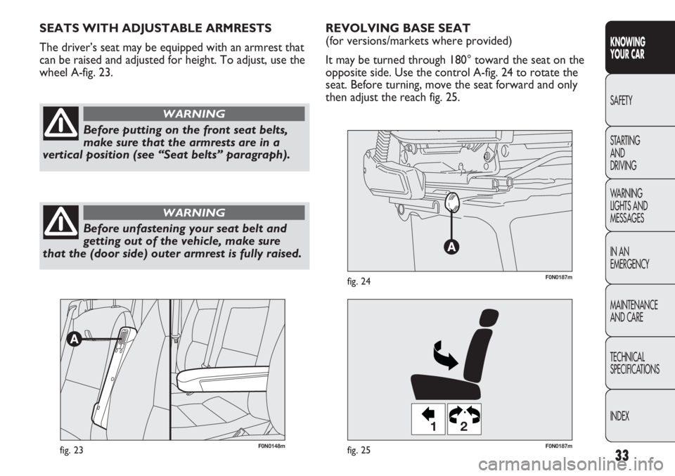
REVOLVING BASE SEAT
(for versions/markets where provided)
It may be turned through 180° toward the seat on the
opposite side. Use the control A-fig. 24 to rotate the
seat. Before turning, move the seat forward and only
then adjust the reach fig. 25. SEATS WITH ADJUSTABLE ARMRESTS
The driver’s seat may be equipped with an armrest that
can be raised and adjusted for height. To adjust, use the
wheel A-fig. 23.
Before putting on the front seat belts,
make sure that the armrests are in a
vertical position (see “Seat belts” paragraph).
WARNING
Before unfastening your seat belt and
getting out of the vehicle, make sure
that the (door side) outer armrest is fully raised.
WARNING
Page 38 of 287
34
KNOWING
YOUR CAR
SAFETY
STARTING
AND
DRIVING
WARNING
LIGHTS AND
MESSAGES
IN AN
EMERGENCY
MAINTENANCE
AND CARE
TECHNICAL
SPECIFICATIONS
INDEX
F0N0173mfig. 26F0N0174mfig. 27
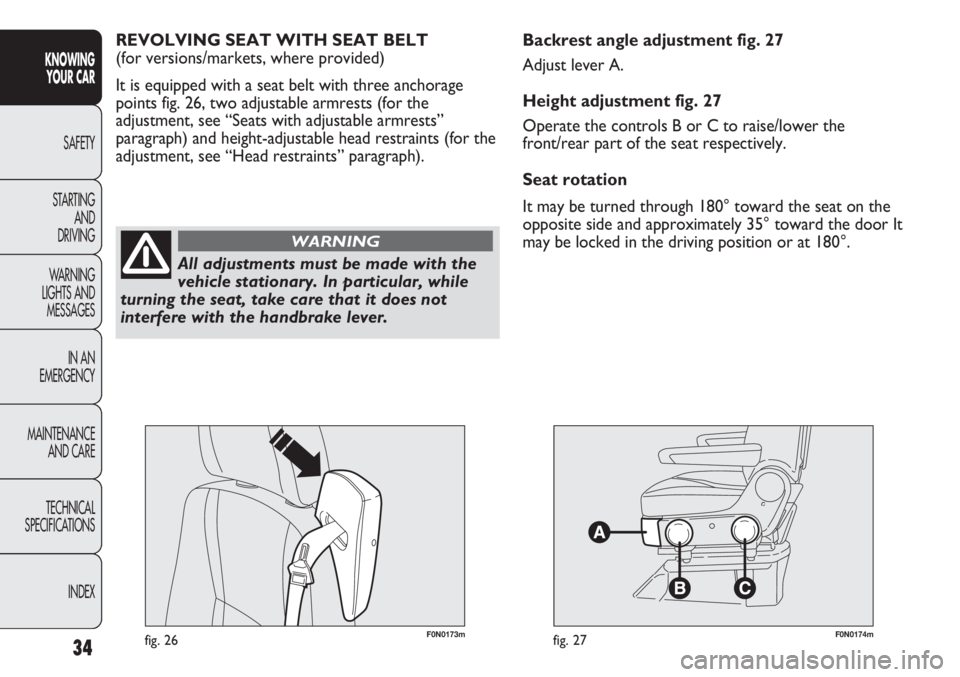
Backrest angle adjustment fig. 27
Adjust lever A.
Height adjustment fig. 27
Operate the controls B or C to raise/lower the
front/rear part of the seat respectively.
Seat rotation
It may be turned through 180° toward the seat on the
opposite side and approximately 35° toward the door It
may be locked in the driving position or at 180°. REVOLVING SEAT WITH SEAT BELT
(for versions/markets, where provided)
It is equipped with a seat belt with three anchorage
points fig. 26, two adjustable armrests (for the
adjustment, see “Seats with adjustable armrests”
paragraph) and height-adjustable head restraints (for the
adjustment, see “Head restraints” paragraph).
All adjustments must be made with the
vehicle stationary. In particular, while
turning the seat, take care that it does not
interfere with the handbrake lever.
WARNING
Page 39 of 287
35
KNOWING
YOUR CAR
SAFETY
STARTING
AND
DRIVING
WARNING
LIGHTS AND
MESSAGES
IN AN
EMERGENCY
MAINTENANCE
AND CARE
TECHNICAL
SPECIFICATIONS
INDEX
F0N0175mfig. 28F0N0213mfig. 29
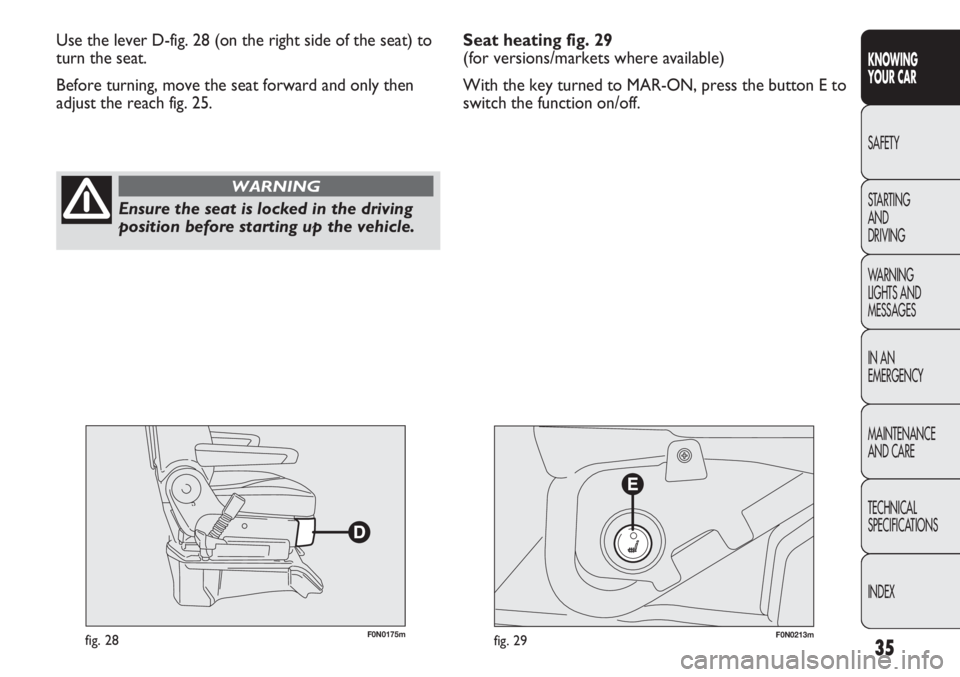
Use the lever D-fig. 28 (on the right side of the seat) to
turn the seat.
Before turning, move the seat forward and only then
adjust the reach fig. 25.
Ensure the seat is locked in the driving
position before starting up the vehicle.
WARNING
Seat heating fig. 29
(for versions/markets where available)
With the key turned to MAR-ON, press the button E to
switch the function on/off.
Page 40 of 287
36
KNOWING
YOUR CAR
SAFETY
STARTING
AND
DRIVING
WARNING
LIGHTS AND
MESSAGES
IN AN
EMERGENCY
MAINTENANCE
AND CARE
TECHNICAL
SPECIFICATIONS
INDEX
F0N0237mfig. 31
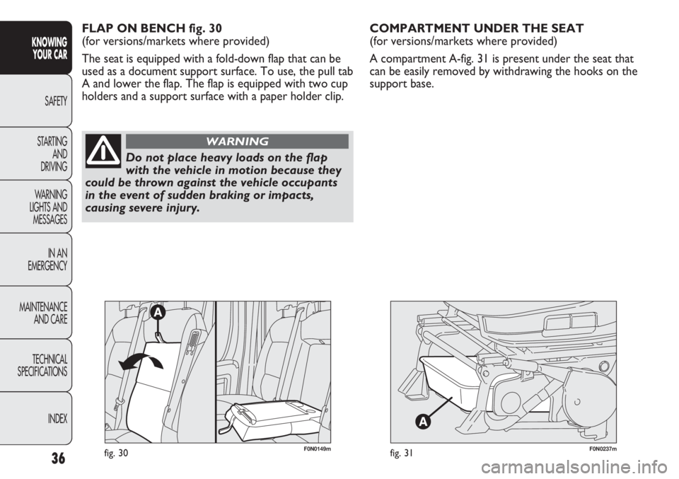
COMPARTMENT UNDER THE SEAT
(for versions/markets where provided)
A compartment A-fig. 31 is present under the seat that
can be easily removed by withdrawing the hooks on the
support base.
Do not place heavy loads on the flap
with the vehicle in motion because they
could be thrown against the vehicle occupants
in the event of sudden braking or impacts,
causing severe injury.
WARNING
FLAP ON BENCH fig. 30
(for versions/markets where provided)
The seat is equipped with a fold-down flap that can be
used as a document support surface. To use, the pull tab
A and lower the flap. The flap is equipped with two cup
holders and a support surface with a paper holder clip.
F0N0149mfig. 30
Page 41 of 287
37
KNOWING
YOUR CAR
SAFETY
STARTING
AND
DRIVING
WARNING
LIGHTS AND
MESSAGES
IN AN
EMERGENCY
MAINTENANCE
AND CARE
TECHNICAL
SPECIFICATIONS
INDEX
F0N0238mfig. 32
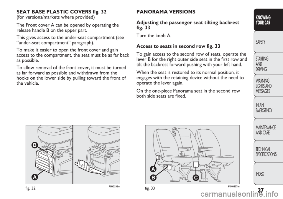
SEAT BASE PLASTIC COVERS fig. 32
(for versions/markets where provided)
The Front cover A can be opened by operating the
release handle B on the upper part.
This gives access to the under-seat compartment (see
“under-seat compartment” paragraph).
To make it easier to open the front cover and gain
access to the compartment, the seat must be as far back
as possible.
To allow removal of the front cover, it must be turned
as far forward as possible and withdrawn from the
hooks on the lower side by pulling toward the front of
the vehicle.
F0N0227mfig. 33
PANORAMA VERSIONS
Adjusting the passenger seat tilting backrest
fig. 33
Turn the knob A.
Access to seats in second row fig. 33
To gain access to the second row of seats, operate the
lever B for the right outer side seat in the first row and
tilt the backrest forward pushing with your left hand.
When the seat is restored to its normal position, it
engages with the retaining device without the need to
operate the lever again.
On the one-piece Panorama seat in the second row
both side seats are fixed.
Page 42 of 287
38
KNOWING
YOUR CAR
SAFETY
STARTING
AND
DRIVING
WARNING
LIGHTS AND
MESSAGES
IN AN
EMERGENCY
MAINTENANCE
AND CARE
TECHNICAL
SPECIFICATIONS
INDEX
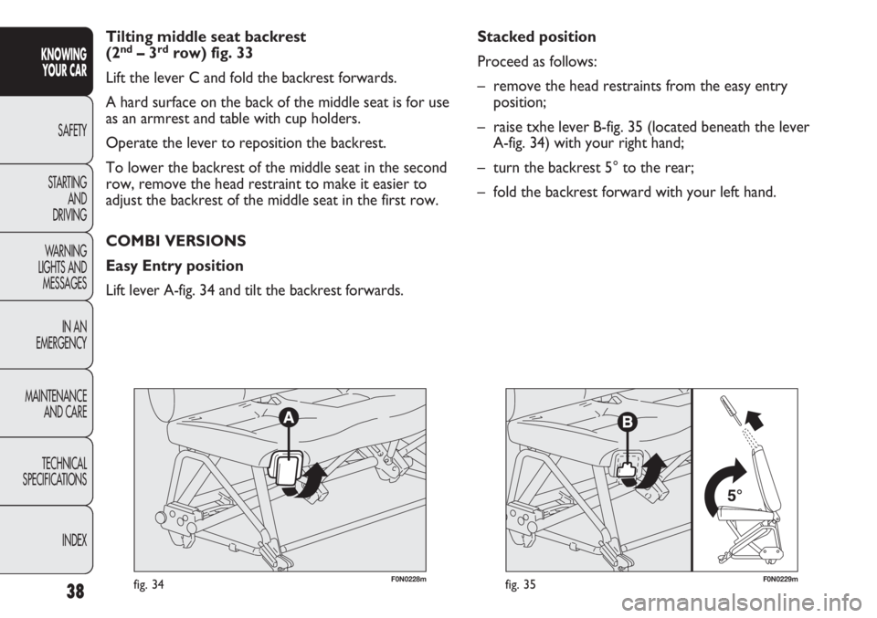
F0N0229mfig. 35
Stacked position
Proceed as follows:
– remove the head restraints from the easy entry
position;
– raise txhe lever B-fig. 35 (located beneath the lever
A-fig. 34) with your right hand;
– turn the backrest 5° to the rear;
– fold the backrest forward with your left hand.
F0N0228mfig. 34
Tilting middle seat backrest
(2nd–3rdrow) fig. 33
Lift the lever C and fold the backrest forwards.
A hard surface on the back of the middle seat is for use
as an armrest and table with cup holders.
Operate the lever to reposition the backrest.
To lower the backrest of the middle seat in the second
row, remove the head restraint to make it easier to
adjust the backrest of the middle seat in the first row.
COMBI VERSIONS
Easy Entry position
Lift lever A-fig. 34 and tilt the backrest forwards.
Page 43 of 287
39
KNOWING
YOUR CAR
SAFETY
STARTING
AND
DRIVING
WARNING
LIGHTS AND
MESSAGES
IN AN
EMERGENCY
MAINTENANCE
AND CARE
TECHNICAL
SPECIFICATIONS
INDEX
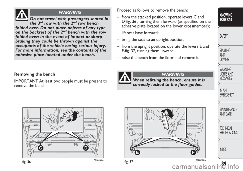
F0N0230mfig. 36
Do not travel with passengers seated in
the 3rdrow with the 2ndrow bench
folded over. Do not place objects of any type
on the backrest of the 2
ndbench with the row
folded over: in the event of impact or sharp
braking they could be thrown against the
occupants of the vehicle casing serious injury.
For more information, see the contents of the
adhesive plate located under the bench.
WARNING
Removing the bench
IMPORTANT At least two people must be present to
remove the bench.
F0N0231mfig. 37
Proceed as follows to remove the bench:
– from the stacked position, operate levers C and
D-fig. 36 , turning them forward (as specified on the
adhesive plate located on the lower crossmember);
– lift seat base forward;
– bring the seat to an upright position;
– from the upright position, operate the levers E and
F-fig. 37, turning them upward;
– raise the bench from the floor and remove it.
When refitting the bench, ensure it is
correctly locked to the floor guides.
WARNING
Page 44 of 287
40
KNOWING
YOUR CAR
SAFETY
STARTING
AND
DRIVING
WARNING
LIGHTS AND
MESSAGES
IN AN
EMERGENCY
MAINTENANCE
AND CARE
TECHNICAL
SPECIFICATIONS
INDEX
To make the best use of the head restraint’s protective
action, adjust the backrest so that your torso is upright
and keep your head as close as possible to the head
restraint.
Head restraints must be adjusted so that
the head, rather than the neck, rests on
them. Only in this case they can protect your
head correctly.
WARNING
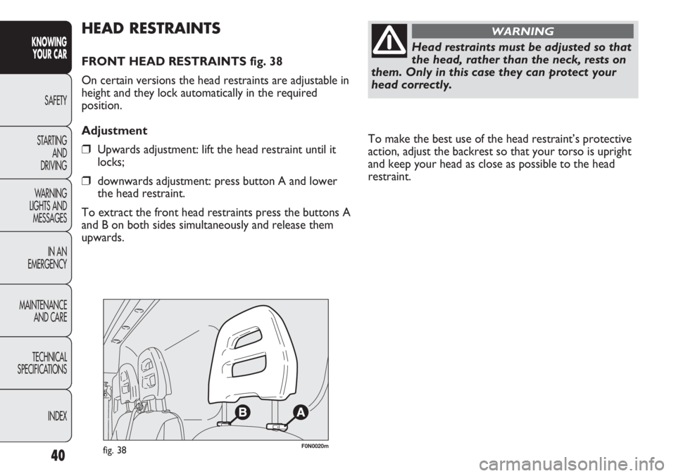
F0N0020mfig. 38
HEAD RESTRAINTS
FRONT HEAD RESTRAINTS fig. 38
On certain versions the head restraints are adjustable in
height and they lock automatically in the required
position.
Adjustment
❒Upwards adjustment: lift the head restraint until it
locks;
❒downwards adjustment: press button A and lower
the head restraint.
To extract the front head restraints press the buttons A
and B on both sides simultaneously and release them
upwards.
Page 45 of 287
41
KNOWING
YOUR CAR
SAFETY
STARTING
AND
DRIVING
WARNING
LIGHTS AND
MESSAGES
IN AN
EMERGENCY
MAINTENANCE
AND CARE
TECHNICAL
SPECIFICATIONS
INDEX
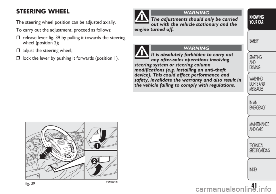
F0N0321mfig. 39
STEERING WHEEL
The steering wheel position can be adjusted axially.
To carry out the adjustment, proceed as follows:
❒release lever fig. 39 by pulling it towards the steering
wheel (position 2);
❒adjust the steering wheel;
❒lock the lever by pushing it forwards (position 1).
The adjustments should only be carried
out with the vehicle stationary and the
engine turned off.
WARNING
It is absolutely forbidden to carry out
any after-sales operations involving
steering system or steering column
modifications (e.g. installing an anti-theft
device). This could affect performance and
safety, invalidate the warranty and also result in
the vehicle failing to comply with regulations.
WARNING
Page 46 of 287
42
KNOWING
YOUR CAR
SAFETY
STARTING
AND
DRIVING
WARNING
LIGHTS AND
MESSAGES
IN AN
EMERGENCY
MAINTENANCE
AND CARE
TECHNICAL
SPECIFICATIONS
INDEX
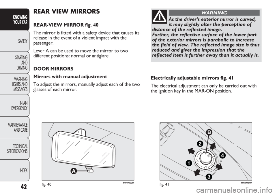
F0N0022mfig. 40F0N0024mfig. 41
Electrically adjustable mirrors fig. 41
The electrical adjustment can only be carried out with
the ignition key in the MAR-ON position.
REAR VIEW MIRRORS
REAR-VIEW MIRROR fig. 40
The mirror is fitted with a safety device that causes its
release in the event of a violent impact with the
passenger.
Lever A can be used to move the mirror to two
different positions: normal or antiglare.
DOOR MIRRORS
Mirrors with manual adjustment
To adjust the mirrors, manually adjust each of the two
glasses of each mirror.
As the driver’s exterior mirror is curved,
it may slightly alter the perception of
distance of the reflected image.
Further, the reflective surface of the lower part
of the exterior mirrors is parabolic to increase
the field of view. The reflected image size is thus
reduced and gives the impression that the
reflected item is further away than it actually is.
WARNING