technical specifications FIAT DUCATO 2012 Owner handbook (in English)
[x] Cancel search | Manufacturer: FIAT, Model Year: 2012, Model line: DUCATO, Model: FIAT DUCATO 2012Pages: 287, PDF Size: 4.5 MB
Page 67 of 287
63
KNOWING
YOUR CAR
SAFETY
STARTING
AND
DRIVING
WARNING
LIGHTS AND
MESSAGES
IN AN
EMERGENCY
MAINTENANCE
AND CARE
TECHNICAL
SPECIFICATIONS
INDEX
F0N0151mfig. 56
To prioritise windscreen demisting, set the air
distribution knob to the
-position.
To obtain both functions, set the air distribution knob
to the
®position.
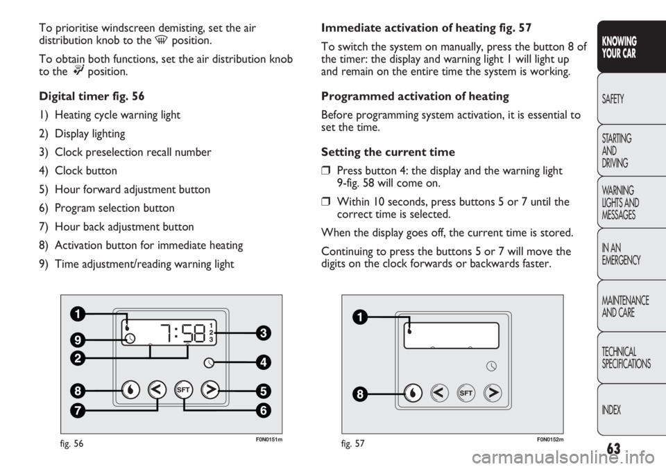
Digital timer fig. 56
1) Heating cycle warning light
2) Display lighting
3) Clock preselection recall number
4) Clock button
5) Hour forward adjustment button
6) Program selection button
7) Hour back adjustment button
8) Activation button for immediate heating
9) Time adjustment/reading warning light
F0N0152mfig. 57
Immediate activation of heating fig. 57
To switch the system on manually, press the button 8 of
the timer: the display and warning light 1 will light up
and remain on the entire time the system is working.
Programmed activation of heating
Before programming system activation, it is essential to
set the time.
Setting the current time
❒Press button 4: the display and the warning light
9-fig. 58 will come on.
❒Within 10 seconds, press buttons 5 or 7 until the
correct time is selected.
When the display goes off, the current time is stored.
Continuing to press the buttons 5 or 7 will move the
digits on the clock forwards or backwards faster.
Page 68 of 287
64
KNOWING
YOUR CAR
SAFETY
STARTING
AND
DRIVING
WARNING
LIGHTS AND
MESSAGES
IN AN
EMERGENCY
MAINTENANCE
AND CARE
TECHNICAL
SPECIFICATIONS
INDEX
F0N0153mfig. 58
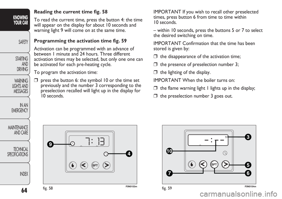
Reading the current time fig. 58
To read the current time, press the button 4: the time
will appear on the display for about 10 seconds and
warning light 9 will come on at the same time.
Programming the activation time fig. 59
Activation can be programmed with an advance of
between 1 minute and 24 hours. Three different
activation times may be selected, but only one one can
be activated for each pre-heating cycle.
To program the activation time:
❒press the button 6: the symbol 10 or the time set
previously and the number 3 corresponding to the
preselection recalled will light up in the display for
10 seconds.
F0N0154mfig. 59
IMPORTANT If you wish to recall other preselected
times, press button 6 from time to time within
10 seconds.
– within 10 seconds, press the buttons 5 or 7 to select
the desired switching on time.
IMPORTANT Confirmation that the time has been
stored is given by:
❒the disappearance of the activation time;
❒the presence of preselection number 3;
❒the lighting of the display.
IMPORTANT When the boiler turns on:
❒the flame warning light 1 lights up in the display;
❒the preselection number 3 goes out.
Page 69 of 287
65
KNOWING
YOUR CAR
SAFETY
STARTING
AND
DRIVING
WARNING
LIGHTS AND
MESSAGES
IN AN
EMERGENCY
MAINTENANCE
AND CARE
TECHNICAL
SPECIFICATIONS
INDEX
Deactivation of the programmed activation time
fig. 59
To delete the programmed activation time, press button
6 briefly: the display lighting will go off and the number 3
relating to the preselected time will disappear.
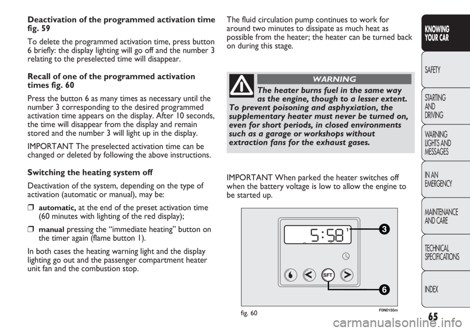
Recall of one of the programmed activation
times fig. 60
Press the button 6 as many times as necessary until the
number 3 corresponding to the desired programmed
activation time appears on the display. After 10 seconds,
the time will disappear from the display and remain
stored and the number 3 will light up in the display.
IMPORTANT The preselected activation time can be
changed or deleted by following the above instructions.
Switching the heating system off
Deactivation of the system, depending on the type of
activation (automatic or manual), may be:
❒automatic,at the end of the preset activation time
(60 minutes with lighting of the red display);
❒manualpressing the “immediate heating” button on
the timer again (flame button 1).
In both cases the heating warning light and the display
lighting go out and the passenger compartment heater
unit fan and the combustion stop.
F0N0155mfig. 60
The fluid circulation pump continues to work for
around two minutes to dissipate as much heat as
possible from the heater; the heater can be turned back
on during this stage.
The heater burns fuel in the same way
as the engine, though to a lesser extent.
To prevent poisoning and asphyxiation, the
supplementary heater must never be turned on,
even for short periods, in closed environments
such as a garage or workshops without
extraction fans for the exhaust gases.
WARNING
IMPORTANT When parked the heater switches off
when the battery voltage is low to allow the engine to
be started up.
Page 70 of 287
66
KNOWING
YOUR CAR
SAFETY
STARTING
AND
DRIVING
WARNING
LIGHTS AND
MESSAGES
IN AN
EMERGENCY
MAINTENANCE
AND CARE
TECHNICAL
SPECIFICATIONS
INDEX
IMPORTANT Before switching the device on, check
that the fuel level is higher than the reserve level.
Otherwise the device could lock and require the
assistance of a Fiat Dealership.
❒Always turn off the heater when refuelling and near
service stations to avoid the risk of explosion or fire
hazards.
❒Do not park the vehicle on inflammable material
such as paper, grass or dry leaves: fire hazard!
❒The temperature near the heater should not exceed
120 °C (e.g. during stove painting in a body shop).
The electronic control unit components may be
damaged at higher temperatures.
❒Whilst the heater is operating with the engine
switched off, it absorbs energy from the battery; the
engine should therefore be left running for a while to
make sure that the battery is properly recharged.
❒To check the coolant level, follow the instructions in
the “Vehicle maintenance” chapter in the “Engine
coolant system fluid” paragraph. The water in the
heating circuit must contain a minimum percentage
of 10% antifreeze.
❒For maintenance and repairs, only contact Fiat
Dealerships and only use genuine spare parts.
F0N0233mfig. 61
MAINTENANCE
Have the additional heater checked regularly at a Fiat
Dealership (and always at the start of every winter).
This will guarantee safe and economic operation of the
heater as well as a long duration.
ADDITIONAL REAR HEATING
(Panorama and Combi)
(for versions/markets, where provided)
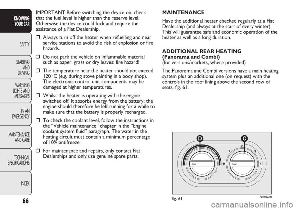
The Panorama and Combi versions have a main heating
system plus an additional one (on request) with the
controls in the roof lining above the second row of
seats, fig. 61.
Page 71 of 287
67
KNOWING
YOUR CAR
SAFETY
STARTING
AND
DRIVING
WARNING
LIGHTS AND
MESSAGES
IN AN
EMERGENCY
MAINTENANCE
AND CARE
TECHNICAL
SPECIFICATIONS
INDEX
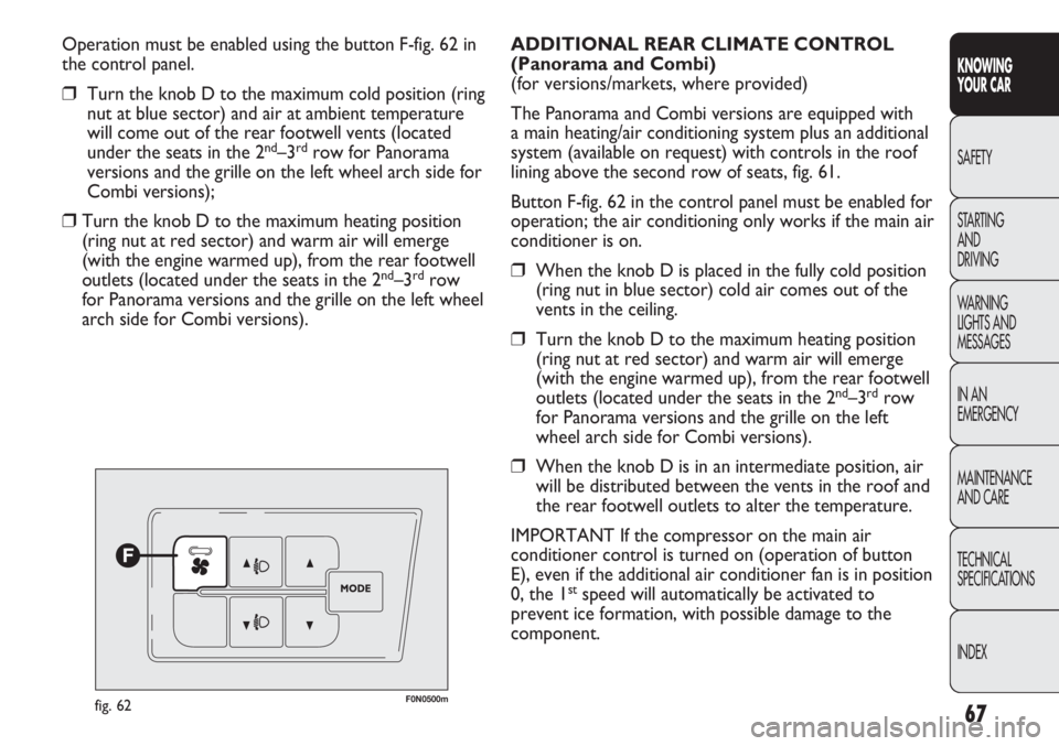
Operation must be enabled using the button F-fig. 62 in
the control panel.
❒Turn the knob D to the maximum cold position (ring
nut at blue sector) and air at ambient temperature
will come out of the rear footwell vents (located
under the seats in the 2
nd–3rdrow for Panorama
versions and the grille on the left wheel arch side for
Combi versions);
❒Turn the knob D to the maximum heating position
(ring nut at red sector) and warm air will emerge
(with the engine warmed up), from the rear footwell
outlets (located under the seats in the 2
nd–3rdrow
for Panorama versions and the grille on the left wheel
arch side for Combi versions).
F0N0500mfig. 62
ADDITIONAL REAR CLIMATE CONTROL
(Panorama and Combi)
(for versions/markets, where provided)
The Panorama and Combi versions are equipped with
a main heating/air conditioning system plus an additional
system (available on request) with controls in the roof
lining above the second row of seats, fig. 61.
Button F-fig. 62 in the control panel must be enabled for
operation; the air conditioning only works if the main air
conditioner is on.
❒When the knob D is placed in the fully cold position
(ring nut in blue sector) cold air comes out of the
vents in the ceiling.
❒Turn the knob D to the maximum heating position
(ring nut at red sector) and warm air will emerge
(with the engine warmed up), from the rear footwell
outlets (located under the seats in the 2
nd–3rdrow
for Panorama versions and the grille on the left
wheel arch side for Combi versions).
❒When the knob D is in an intermediate position, air
will be distributed between the vents in the roof and
the rear footwell outlets to alter the temperature.
IMPORTANT If the compressor on the main air
conditioner control is turned on (operation of button
E), even if the additional air conditioner fan is in position
0, the 1
stspeed will automatically be activated to
prevent ice formation, with possible damage to the
component.
Page 72 of 287
68
KNOWING
YOUR CAR
SAFETY
STARTING
AND
DRIVING
WARNING
LIGHTS AND
MESSAGES
IN AN
EMERGENCY
MAINTENANCE
AND CARE
TECHNICAL
SPECIFICATIONS
INDEX
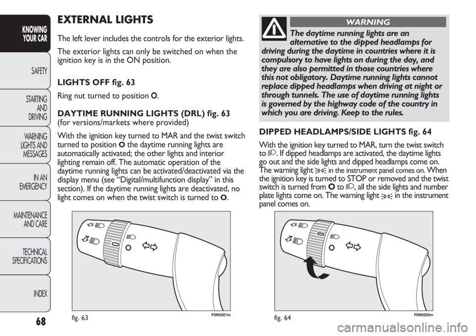
F0N0501mfig. 63F0N0502mfig. 64
EXTERNAL LIGHTS
The left lever includes the controls for the exterior lights.
The exterior lights can only be switched on when the
ignition key is in the ON position.
LIGHTS OFF fig. 63
Ring nut turned to position
O.
DAYTIME RUNNING LIGHTS (DRL) fig. 63
(for versions/markets where provided)
With the ignition key turned to MAR and the twist switch
turned to position
Othe daytime running lights are
automatically activated; the other lights and interior
lighting remain off. The automatic operation of the
daytime running lights can be activated/deactivated via the
display menu (see “Digital/multifunction display” in this
section). If the daytime running lights are deactivated, no
light comes on when the twist switch is turned to
O.DIPPED HEADLAMPS/SIDE LIGHTS fig. 64
With the ignition key turned to MAR, turn the twist switch
to
2. If dipped headlamps are activated, the daytime lights
go out and the side lights and dipped headlamps come on.
The warning light
3in the instrument panel comes on. When
the ignition key is turned to STOP or removed and the twist
switch is turned from Oto
2, all the side lights and number
plate lights come on. The warning light
3in the instrument
panel comes on.
The daytime running lights are an
alternative to the dipped headlamps for
driving during the daytime in countries where it is
compulsory to have lights on during the day, and
they are also permitted in those countries where
this not obligatory. Daytime running lights cannot
replace dipped headlamps when driving at night or
through tunnels. The use of daytime running lights
is governed by the highway code of the country in
which you are driving. Keep to the rules.
WARNING
Page 73 of 287
69
KNOWING
YOUR CAR
SAFETY
STARTING
AND
DRIVING
WARNING
LIGHTS AND
MESSAGES
IN AN
EMERGENCY
MAINTENANCE
AND CARE
TECHNICAL
SPECIFICATIONS
INDEX
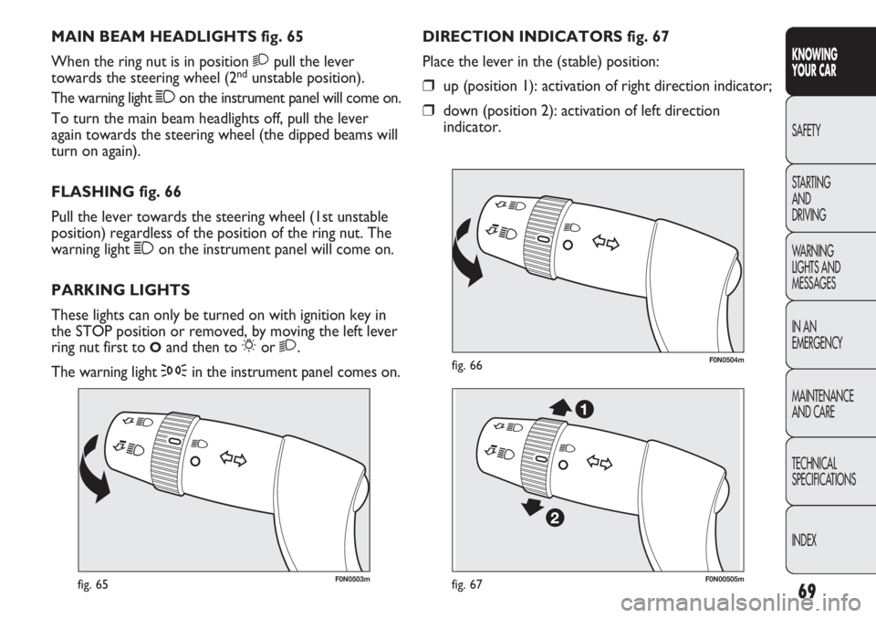
F0N0503mfig. 65
F0N0504mfig. 66
DIRECTION INDICATORS fig. 67
Place the lever in the (stable) position:
❒up (position 1): activation of right direction indicator;
❒down (position 2): activation of left direction
indicator. MAIN BEAM HEADLIGHTS fig. 65
When the ring nut is in position 2pull the lever
towards the steering wheel (2
ndunstable position).
The warning light 1on the instrument panel will come on.
To turn the main beam headlights off, pull the lever
again towards the steering wheel (the dipped beams will
turn on again).
FLASHING fig. 66
Pull the lever towards the steering wheel (1st unstable
position) regardless of the position of the ring nut. The
warning light 1on the instrument panel will come on.
PARKING LIGHTS
These lights can only be turned on with ignition key in
the STOP position or removed, by moving the left lever
ring nut first to
Oand then to 6or 2.
The warning light
3in the instrument panel comes on.
F0N00505mfig. 67
Page 74 of 287
70
KNOWING
YOUR CAR
SAFETY
STARTING
AND
DRIVING
WARNING
LIGHTS AND
MESSAGES
IN AN
EMERGENCY
MAINTENANCE
AND CARE
TECHNICAL
SPECIFICATIONS
INDEX
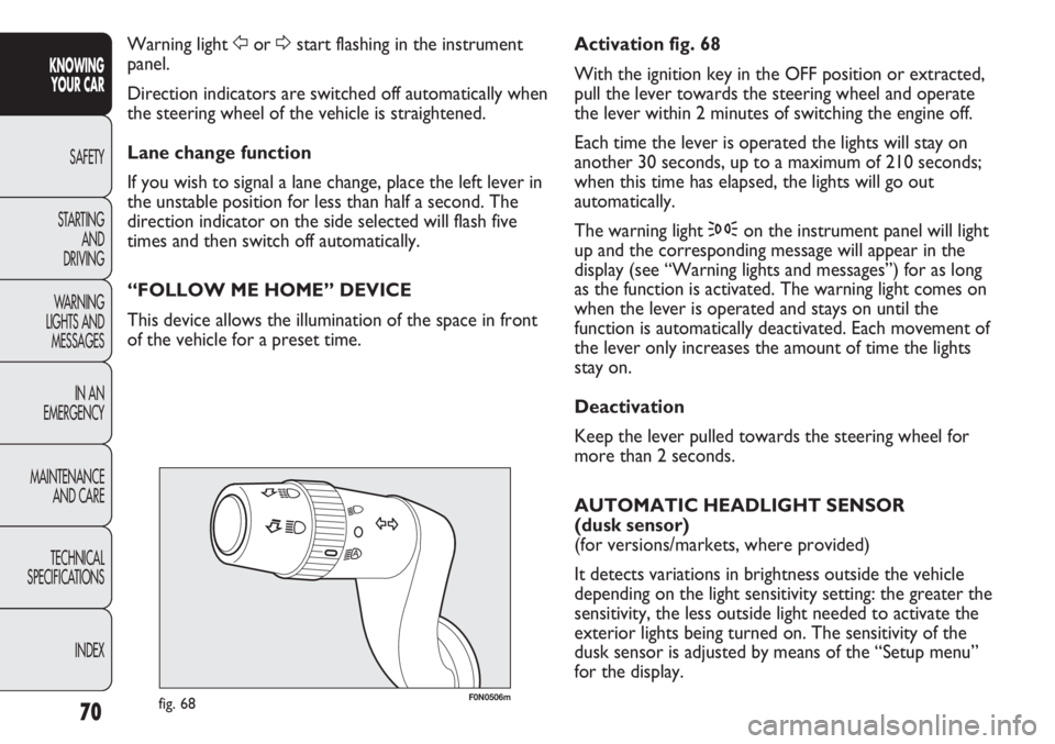
F0N0506mfig. 68
Activation fig. 68
With the ignition key in the OFF position or extracted,
pull the lever towards the steering wheel and operate
the lever within 2 minutes of switching the engine off.
Each time the lever is operated the lights will stay on
another 30 seconds, up to a maximum of 210 seconds;
when this time has elapsed, the lights will go out
automatically.
The warning light 3on the instrument panel will light
up and the corresponding message will appear in the
display (see “Warning lights and messages”) for as long
as the function is activated. The warning light comes on
when the lever is operated and stays on until the
function is automatically deactivated. Each movement of
the lever only increases the amount of time the lights
stay on.
Deactivation
Keep the lever pulled towards the steering wheel for
more than 2 seconds.
AUTOMATIC HEADLIGHT SENSOR
(dusk sensor)
(for versions/markets, where provided)
It detects variations in brightness outside the vehicle
depending on the light sensitivity setting: the greater the
sensitivity, the less outside light needed to activate the
exterior lights being turned on. The sensitivity of the
dusk sensor is adjusted by means of the “Setup menu”
for the display. Warning light For Dstart flashing in the instrument
panel.
Direction indicators are switched off automatically when
the steering wheel of the vehicle is straightened.
Lane change function
If you wish to signal a lane change, place the left lever in
the unstable position for less than half a second. The
direction indicator on the side selected will flash five
times and then switch off automatically.
“FOLLOW ME HOME” DEVICE
This device allows the illumination of the space in front
of the vehicle for a preset time.
Page 75 of 287
71
KNOWING
YOUR CAR
SAFETY
STARTING
AND
DRIVING
WARNING
LIGHTS AND
MESSAGES
IN AN
EMERGENCY
MAINTENANCE
AND CARE
TECHNICAL
SPECIFICATIONS
INDEX
F0N0507mfig. 69
WINDOW WASHING
WINDSCREEN WASHER/WIPER
The device can operate only when the ignition key is in
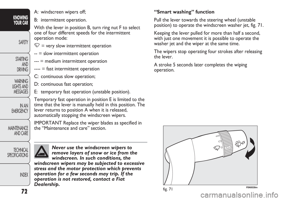
the MAR-ON position. There are five different positions
for the right lever fig. 70: Activation fig. 69
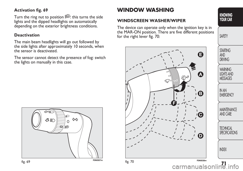
Turn the ring nut to position 2A: this turns the side
lights and the dipped headlights on automatically
depending on the exterior brightness conditions.
Deactivation
The main beam headlights will go out followed by
the side lights after approximately 10 seconds, when
the sensor is deactivated.
The sensor cannot detect the presence of fog: switch
the lights on manually in this case.
fig. 70F0N0038m
Page 76 of 287
72
KNOWING
YOUR CAR
SAFETY
STARTING
AND
DRIVING
WARNING
LIGHTS AND
MESSAGES
IN AN
EMERGENCY
MAINTENANCE
AND CARE
TECHNICAL
SPECIFICATIONS
INDEX
F0N0039mfig. 71
“Smart washing” function
Pull the lever towards the steering wheel (unstable
position) to operate the windscreen washer jet, fig. 71.
Keeping the lever pulled for more than half a second,
with just one movement it is possible to operate the
washer jet and the wiper at the same time.
The wipers stop operating four strokes after releasing
the lever.
A stroke 5 seconds later completes the wiping
operation. A: windscreen wipers off;
B: intermittent operation.
With the lever in position B, turn ring nut F to select
one of four different speeds for the intermittent
operation mode:
,= very slow intermittent operation
-- = slow intermittent operation
--- = medium intermittent operation
---- = fast intermittent operation
C: continuous slow operation;
D: continuous fast operation;
E: temporary fast operation (unstable position).
Temporary fast operation in position E is limited to the
time that the lever is manually held in this position. The
lever returns to position A when it is released,
automatically stopping the windscreen wipers.
IMPORTANT Replace the wiper blades as specified in
the “Maintenance and care” section.
Never use the windscreen wipers to
remove layers of snow or ice from the
windscreen. In such conditions, the
windscreen wipers may be subjected to excessive
stress and the motor protection which prevents
operation for a few seconds may trip. If the
operation is not restored, contact a Fiat
Dealership.