FIAT DUCATO BASE CAMPER 2018 Owner handbook (in English)
Manufacturer: FIAT, Model Year: 2018, Model line: DUCATO BASE CAMPER, Model: FIAT DUCATO BASE CAMPER 2018Pages: 304, PDF Size: 14.93 MB
Page 151 of 304
 REPLACING A BULB
GENERAL
INSTRUCTIONS
140) 141)
47)
When a light is not working, check
that the corresponding fuse is intact
before changing a bulb. For the location
of fuses, refer to the paragraph
&")
REPLACING A BULB
GENERAL
INSTRUCTIONS
140) 141)
47)
When a light is not working, check
that the corresponding fuse is intact
before changing a bulb. For the location
of fuses, refer to the paragraph
"Replacing fuses" in this chapter.
before changing a bulb check the
contacts for oxidation;
burnt bulbs must be replaced by
others of the same type and power;
always check the headlight beam
direction after changing a bulb;
IMPORTANT A slight misting may
appear on the internal surface of the
headlight: this does not indicate a fault
and is caused by low temperature
and the degree of humidity in the air.
Misting will rapidly disappear when the
headlights are switched on. The
presence of drops inside the headlights
indicates infiltration of water. Contact
a Fiat Dealership.
WARNING
140)Modifications or repairs to the
electric system that are not carried out
properly or do not take the system
technical specifications into account can
cause malfunctions leading to the risk
of fire.
141)Halogen bulbs contain pressurised
gas, in the case of breakage they may
burst causing glass fragments to be
projected outwards.
WARNING
47)Halogen bulbs must be handled
holding the metallic part only. Touching the
transparent part of the bulb with your
fingers may reduce the intensity of the
emitted light and even reduce the lifespan
of the bulb. In the event of accidental
contact, wipe the bulb with a cloth
moistened with alcohol and let the bulb
dry.
149
Page 152 of 304
 BULB TYPES
Various types of bulbs are fitted to your vehicle.
All-glass bulb:(type A) these
are pressure fitted - pull to remove.
Bayonet bulb:(type B) to remove them press the bulb and turn it
anticl")
BULB TYPES
Various types of bulbs are fitted to your vehicle.
All-glass bulb:(type A) these
are pressure fitted - pull to remove.
Bayonet bulb:(type B) to remove them press the bulb and turn it
anticlockwise.
Cylindrical bulbs:(type C) release them from their contacts to remove.
Halogen bulbs:(type D) to remove the bulb, release it and extract it
from its seat.
Halogen bulbs:(type E) to remove the bulb, release it and extract it
from its seat.
150
IN AN EMERGENCY
Page 153 of 304
 Light bulbs
 Type Power Figure ref.
Main beam headlights H7 55W D
Dipped beam headlights H7 55W D
Front side lights / daytime running lights
W21/5W - LED
(#)--
Front fog lights
(*)H11 55W -")
Light bulbs
Light bulbs Type Power Figure ref.
Main beam headlights H7 55W D
Dipped beam headlights H7 55W D
Front side lights / daytime running lights
W21/5W - LED
(#)--
Front fog lights
(*)H11 55W -
Front direction indicators WY21W 21W B
Side turn lightW16WF
(**) / WY5W
(***)16W(**) / 5W (***)A
Rear direction indicators PY2IW 21W B
Side lights W5W 5W A
Rear side lights P21/5W 21/5W B
Rear side lights/Brake lights P21W 21W B
Third brake light W5W 5W B
Reverse gear W16W 16W B
Rear fog light W16W 16W B
Number plate C5W 5W A
Front roof light (movable lens) 12V10W 10W C
Rear ceiling light 12V10W 10W C
(#) where provided, instead of bulb W21/5W
(*)for versions/markets, where provided
(**)XL and Tempo Libero versions
(***)all other versions
151
Page 154 of 304
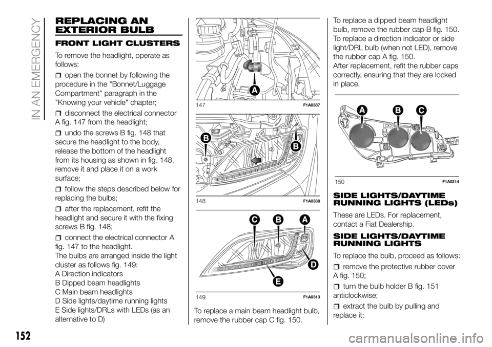
REPLACING AN
EXTERIOR BULB
FRONT LIGHT CLUSTERS
To remove the headlight, operate as
follows:
open the bonnet by following the
procedure in the "Bonnet/Luggage
Compartment" paragraph in the
"Knowing your vehicle" chapter;
disconnect the electrical connector
A fig. 147 from the headlight;
undo the screws B fig. 148 that
secure the headlight to the body,
release the bottom of the headlight
from its housing as shown in fig. 148,
remove it and place it on a work
surface;
follow the steps described below for
replacing the bulbs;
after the replacement, refit the
headlight and secure it with the fixing
screws B fig. 148;
connect the electrical connector A
fig. 147 to the headlight.
The bulbs are arranged inside the light
cluster as follows fig. 149:
A Direction indicators
B Dipped beam headlights
C Main beam headlights
D Side lights/daytime running lights
E Side lights/DRLs with LEDs (as an
alternative to D)To replace a main beam headlight bulb,
remove the rubber cap C fig. 150.To replace a dipped beam headlight
bulb, remove the rubber cap B fig. 150.
To replace a direction indicator or side
light/DRL bulb (when not LED), remove
the rubber cap A fig. 150.
After replacement, refit the rubber caps
correctly, ensuring that they are locked
in place.
SIDE LIGHTS/DAYTIME
RUNNING LIGHTS (LEDs)
These are LEDs. For replacement,
contact a Fiat Dealership.
SIDE LIGHTS/DAYTIME
RUNNING LIGHTS
To replace the bulb, proceed as follows:
remove the protective rubber cover
A fig. 150;
turn the bulb holder B fig. 151
anticlockwise;
extract the bulb by pulling and
replace it;
147F1A0337
148F1A0338
149F1A0313
150F1A0314
152
IN AN EMERGENCY
Page 155 of 304
 remove the bulb by pushing it
slightly and turning it anticlockwise
(bayonet mount);
refit the bulb holder B by turning it
clockwise and making sure that it locks
correctly
refit the protective rubber")
remove the bulb by pushing it
slightly and turning it anticlockwise
(bayonet mount);
refit the bulb holder B by turning it
clockwise and making sure that it locks
correctly
refit the protective rubber cover A
fig. 150.
MAIN BEAM HEADLIGHTSTo replace the bulb, proceed as follows:
remove the protective rubber cover
C fig. 150;
free the bulb holder A fig. 152 from
the side clips B and remove it;
disconnect the electrical connector;
fit the new bulb, ensuring that the
outline of the metal part coincides with
the grooves on the curve of the
headlight, pressing to engage it with the
side clips;
reconnect the electrical connector;
refit the protective rubber cover
C fig. 150.
DIPPED BEAM
HEADLIGHTS
With incandescent bulbs
To replace the bulb, proceed as follows:
remove the protective rubber cover
B fig. 150;
free the bulb holder A fig. 153 from
the side clips B and remove it;
disconnect the electrical connector;
fit the new bulb, ensuring that the
outline of the metal part coincides with
the grooves on the curve of the
headlight, pressing to engage it with the
side clips;
reconnect the electrical connector;
refit the protective rubber cover
B fig. 150.
DIRECTION INDICATORS
To replace the bulb, proceed as follows:
remove the protective rubber cover
A fig. 150;
turn the bulb holder B fig. 154
anticlockwise;
extract the bulb by pulling and
replace it;
remove the bulb by pushing it
slightly and turning it anticlockwise
(bayonet mount);
refit the bulb holder B by turning it
clockwise and making sure that it locks
correctly
refit the protective rubber cover A
fig. 150.
151F1A0386
152F1A0315
153F1A0316
153
Page 156 of 304
 Side
To change the bulbs, proceed as
follows fig. 155:
move the mirror manually to permit
access to the two fixing screws A;
using the Phillips screwdriver
provided, undo the screws and extract
the bu")
Side
To change the bulbs, proceed as
follows fig. 155:
move the mirror manually to permit
access to the two fixing screws A;
using the Phillips screwdriver
provided, undo the screws and extract
the bulb holder assembly, releasing it
from the teeth;
undo the bulb and replace bulb B,
turning it anticlockwise.FOG LIGHTS
(for versions/markets, where provided)
To replace the front fog light bulbs,
proceed as follows:
steer the wheel completely inwards;
undo the screw A and remove the
flap B fig. 156;
release the clip C fig. 157 and
disconnect the electrical connector D;
turn and remove the bulb holder E;
release the bulb and replace it;
refit the new bulb and carry out the
procedure described previously in
reverse.REAR LIGHT CLUSTERS
The bulbs are arranged inside the light
cluster as follows fig. 158:
A brake/side lights
B side light
C direction indicators
D reverse lights.
E rear fog lights
To replace the bulb, proceed as follows
fig. 159, fig. 160:
open the rear wing door.
154F1A0317
155F1A0195
156F1A0361
157F1A0362
158F1A0318
154
IN AN EMERGENCY
Page 157 of 304
 undo the 7 fixing screws A of the
plastic cover;
undo the two fixing screws B;
extract the unit outwards and
disconnect the electrical connector;
unscrew the screws C using the
screwdriver provided an")
undo the 7 fixing screws A of the
plastic cover;
undo the two fixing screws B;
extract the unit outwards and
disconnect the electrical connector;
unscrew the screws C using the
screwdriver provided and remove the
bulb holder;
remove the bulb D, E, F pushing it
gently and turning it anticlockwise
(“bayonet” locking), then replace it;
remove the bulb G, H pulling outwards;
refit the bulb holder and tighten the
screws C;
reconnect the electrical connector,
correctly reposition the unit on the body
of the vehicle and then tighten the
fixing screws B;
refit the plastic cover fastening it
with the 7 fixing screws A.For truck and chassis cab versions:
Undo the four screws H fig. 161 and
replace the bulbs:
I bulb for rear fog light
L bulb for reversing light
M bulb for side light
N bulb for brake light
O bulb for side light.
159F1A0319160F1A0320
161F1A0200
155
Page 158 of 304
 THIRD BRAKE LIGHTS
To replace the bulb proceed as follows:
undo the two fixing screws A fig.
162;
extract the lens unit;
press the tabs B fig. 163 together
and remove the bulb holder;
remove the snap-")
THIRD BRAKE LIGHTS
To replace the bulb proceed as follows:
undo the two fixing screws A fig.
162;
extract the lens unit;
press the tabs B fig. 163 together
and remove the bulb holder;
remove the snap-fitted bulb and
replace.NUMBER PLATE LIGHTS
To replace the bulb proceed as follows:
operate in the point indicated by
the arrow and remove the lens unit A
fig. 164;
change the bulb releasing it from the
side contacts and making sure the
new bulb is correctly fastened between
the contacts;
refit the snap-fitted lens unit.
SIDE LIGHTS
(for versions/markets, where provided)
To replace the bulb proceed as follows:
for extra-long van:
– undo the two fixing screws C fig. 165
and remove the headlight;
– remove the bulb holder D on the rear
of the light cluster, turning it through
a 1/4 turn;
– remove the snap-fitted bulb and
replace.
for chassis cabs with platform:
– remove the bulb-holder on the rear of
the light cluster, turning through 1/4
turn;
– remove the snap-fitted bulb and
replace.162F1A0204
163F1A0205
164F1A0206
165F1A0207
156
IN AN EMERGENCY
Page 159 of 304
 REPLACING
INTERIOR BULBS
For the type of bulb and relevant power
rating, see “Changing a bulb”.
FRONT CEILING LIGHT
To replace the bulbs, proceed as
follows:
operate in the point shown by the
arro")
REPLACING
INTERIOR BULBS
For the type of bulb and relevant power
rating, see “Changing a bulb”.
FRONT CEILING LIGHT
To replace the bulbs, proceed as
follows:
operate in the point shown by the
arrow and remove the roof light A
fig. 166;
open protective flap B fig. 167;
replace the bulbs C fig. 167
by releasing them from the side
contacts and making sure that the new
bulbs are correctly secured between
the contacts;
re-close the flap B fig. 167 and
fasten the roof light A fig. 166 in its
housing, making sure that it locks into
place.
REAR CEILING LIGHT
To replace the bulbs, proceed as
follows:
operate in the points indicated by
the arrows and remove the roof light D
fig. 168;
open protective flap E fig. 169;
replace the bulb F fig. 169 by
releasing it from the side contacts and
making sure that the new bulb is
correctly secured between the
contacts;
close the protective flap E fig. 169
and refit the roof light D fig. 168 in
its housing, making sure that it locks
into place.
166F1A0208
167F1A0209
168F1A0210
169F1A0211
157
Page 160 of 304
 REPLACING FUSES
GENERAL INFORMATION
142) 143) 144) 145)
48)
Fuses protect the electrical system:
they intervene (blow) in the event of a
failure or improper action on the
system. When a device does no")
REPLACING FUSES
GENERAL INFORMATION
142) 143) 144) 145)
48)
Fuses protect the electrical system:
they intervene (blow) in the event of a
failure or improper action on the
system. When a device does not work,
check the condition of its protection
fuse: the filament A fig. 170 must be
intact. If it is not, replace the blown fuse
with another with the same amperage
(same colour).
B intact fuse.
C fuse with damaged filament.FUSE LOCATION
The vehicle fuses are grouped in three
control units located on the dashboard,
passenger compartment right pillar
and engine compartment.
DASHBOARD FUSEBOX
To access the dashboard fuse box fig.
171, undo the screws A fig. 172 and
remove the cover.ENGINE COMPARTMENT
FUSEBOX – OPTIONAL WIRING
MODULE
To access the fusebox fig. 174 - fig.
175 - fig. 176 - fig. 177, remove its
protective cover fig. 173.
Proceed as follows:
fully tighten the captive screw using
the dedicated Phillips screwdriver
provided;
170F1A0212171F1A0214
172F1A0213
173F1A0334
158
IN AN EMERGENCY