FIAT DUCATO BASE CAMPER 2018 Owner handbook (in English)
Manufacturer: FIAT, Model Year: 2018, Model line: DUCATO BASE CAMPER, Model: FIAT DUCATO BASE CAMPER 2018Pages: 304, PDF Size: 14.93 MB
Page 171 of 304
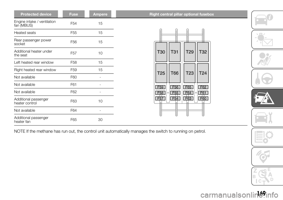
Protected device Fuse Ampere Right central pillar optional fusebox
Engine intake / ventilation
fan (MBUS)F54 15
Heated seats F55 15
Rear passenger power
socketF56 15
Additional heater under
the seatF57 10
Left heated rear window F58 15
Right heated rear window F59 15
Not available F60 -
Not available F61 -
Not available F62 -
Additional passenger
heater controlF63 10
Not available F64 -
Additional passenger
heater fanF65 30
NOTE If the methane has run out, the control unit automatically manages the switch to running on petrol.
169
Page 172 of 304
WARNING
142)Never replace a fuse with another with a higher amp rating; DANGER OF FIRE. If a general protection fuse (MEGA-FUSE, MIDI-FUSE) is
activated, contact a Fiat Dealership.
143)Before replacing a fuse, make sure that the ignition key has been removed and that all the other services are switched off and/or
disengaged.
144)If the replaced fuse blows again, contact a Fiat Dealership.
145)Contact Fiat Dealership if a safety system (airbags, brakes), engine system (engine, gearbox) or steering system general protection fuse
blows.
WARNING
48)Never replace a faulty fuse with metal wires or anything else.
170
IN AN EMERGENCY
Page 173 of 304
GATEWAY FMS
MODULE
The Gateway FMS Module provides the
interface between the vehicle data
network and the FMS standard.
FMS: The Fleet Management Systems
Interface (FMS) is a standard interface
that allows the vehicle’s digital
electronic control unit signals to be
read. The information in these signals
can be used to facilitate the vehicle’s
personalisation or special outfitting. The
Gateway FMS Module supports the
following FMS Standard versions:
FMS - Standard Interface
description Vers. 02 (available on
http://www.fms-standard.com/Truck/
index.htm)
Bus FMS - Standard Interface
description Vers. 02 (available
onhttp://www.fms-standard.com/Bus/
index.htm)
We advise having the Gateway FMS
Module installed by the Fiat Dealership
or specialist technicians. The fitting
instructions are in the Fitters/Installers
Manual on the HYPERLINK website
"http://www.fiatprofessional-
converters.com"www.fiatprofessional-
converters.com.The following table shows all signals
available to control units interfaced with
the Gateway FMS Module.
171
Page 174 of 304
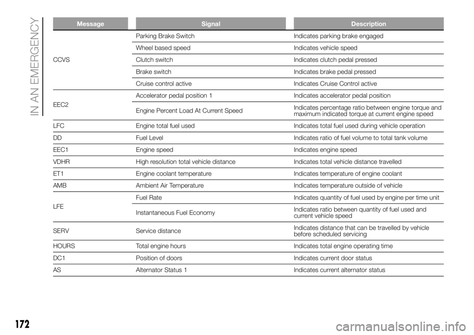
Message Signal Description
CCVSParking Brake Switch Indicates parking brake engaged
Wheel based speed Indicates vehicle speed
Clutch switch Indicates clutch pedal pressed
Brake switch Indicates brake pedal pressed
Cruise control active Indicates Cruise Control active
EEC2Accelerator pedal position 1 Indicates accelerator pedal position
Engine Percent Load At Current SpeedIndicates percentage ratio between engine torque and
maximum indicated torque at current engine speed
LFC Engine total fuel used Indicates total fuel used during vehicle operation
DD Fuel Level Indicates ratio of fuel volume to total tank volume
EEC1 Engine speed Indicates engine speed
VDHR High resolution total vehicle distance Indicates total vehicle distance travelled
ET1 Engine coolant temperature Indicates temperature of engine coolant
AMB Ambient Air Temperature Indicates temperature outside of vehicle
LFEFuel Rate Indicates quantity of fuel used by engine per time unit
Instantaneous Fuel EconomyIndicates ratio between quantity of fuel used and
current vehicle speed
SERV Service distanceIndicates distance that can be travelled by vehicle
before scheduled servicing
HOURS Total engine hours Indicates total engine operating time
DC1 Position of doors Indicates current door status
AS Alternator Status 1 Indicates current alternator status
172
IN AN EMERGENCY
Page 175 of 304
Message Signal Description
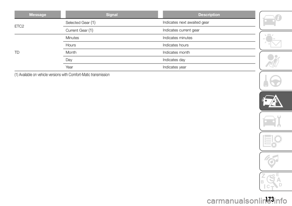
ETC2Selected Gear(1)Indicates next awaited gear
Current Gear
(1)Indicates current gear
TDMinutes Indicates minutes
Hours Indicates hours
Month Indicates month
Day Indicates day
Year Indicates year
(1) Available on vehicle versions with Comfort-Matic transmission
173
Page 176 of 304
Message Signal Description
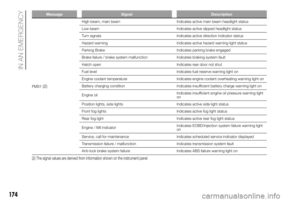
FMS1(2)
High beam, main beam Indicates active main beam headlight status
Low beam Indicates active dipped headlight status
Turn signals Indicates active direction indicator status
Hazard warning Indicates active hazard warning light status
Parking Brake Indicates parking brake engaged
Brake failure / brake system malfunction Indicates braking system fault
Hatch open Indicates rear door not shut
Fuel level Indicates fuel reserve warning light on
Engine coolant temperature Indicates engine coolant overheating warning light on
Battery charging condition Indicates insufficient battery charge warning light on
Engine oilIndicates insufficient engine oil pressure warning light
on
Position lights, side lights Indicates active side light status
Front fog lights Indicates active fog light status
Rear fog light Indicates active rear fog light status
Engine / Mil indicatorIndicates EOBD/injection system failure warning light
on
Service, call for maintenance Indicates scheduled service indicator displayed
Transmission failure / malfunction Indicates transmission system fault
Anti-lock brake system failure Indicates ABS failure warning light on
(2) The signal values are derived from information shown on the instrument panel
174
IN AN EMERGENCY
Page 177 of 304
Message Signal Description
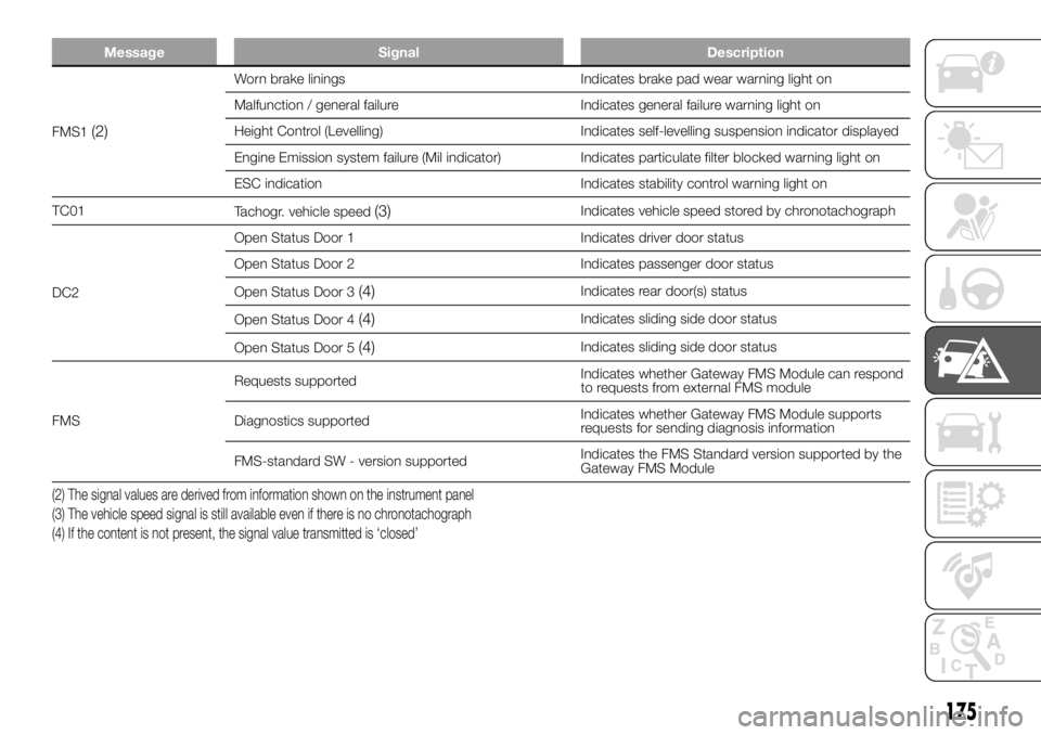
FMS1(2)
Worn brake linings Indicates brake pad wear warning light on
Malfunction / general failure Indicates general failure warning light on
Height Control (Levelling) Indicates self-levelling suspension indicator displayed
Engine Emission system failure (Mil indicator) Indicates particulate filter blocked warning light on
ESC indication Indicates stability control warning light on
TC01
Tachogr. vehicle speed
(3)Indicates vehicle speed stored by chronotachograph
DC2Open Status Door 1 Indicates driver door status
Open Status Door 2 Indicates passenger door status
Open Status Door 3
(4)Indicates rear door(s) status
Open Status Door 4
(4)Indicates sliding side door status
Open Status Door 5
(4)Indicates sliding side door status
FMSRequests supportedIndicates whether Gateway FMS Module can respond
to requests from external FMS module
Diagnostics supportedIndicates whether Gateway FMS Module supports
requests for sending diagnosis information
FMS-standard SW - version supportedIndicates the FMS Standard version supported by the
Gateway FMS Module
(2) The signal values are derived from information shown on the instrument panel
(3) The vehicle speed signal is still available even if there is no chronotachograph
(4) If the content is not present, the signal value transmitted is ‘closed’
175
Page 178 of 304
CHANGING A WHEEL
GENERAL
INSTRUCTIONS
Wheel replacement and correct use of
the jack and spare wheel (for
versions/markets, where provided) call
for some precautions, which are listed
below.
146) 147) 148) 149) 150)
Please note that:
the jack weight is 4.5 kg;
the jack requires no adjustment;
the jack cannot be repaired: in the
event of a fault it must be replaced
by another original one;
no tool other than its cranking
device may be fitted on the jack.
151)
To change a wheel, proceed as
follows:
stop the vehicle in a position that is
not dangerous for oncoming traffic
where you can change the wheel safely.
The ground must be flat and sufficiently
compact;
switch off the engine and pull the
handbrake;
engage first gear or reverse;
put on the reflective safety jacket
(compulsory by law in certain countries)
before getting out of the vehicle;
indicate that the vehicle has broken
down using the devices required by
the law in the current country (e.g.
warning triangle, hazard lights, etc.);
in the event of a wheel change on a
slope or on unsurfaced roads, put
any object as stop under the wheels;
take the tool bag from under the
passenger seat (see "Compartment
under the front passenger side seat" in
the "Internal equipment" chapter in
"Knowing the vehicle").
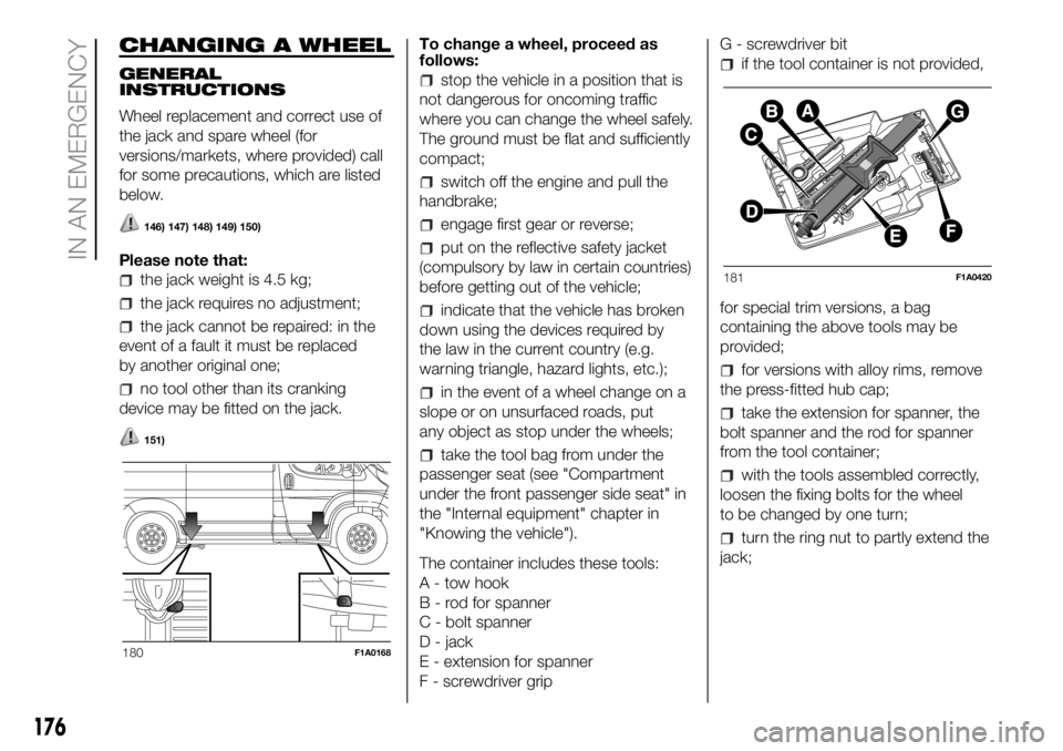
The container includes these tools:
A - tow hook
B - rod for spanner
C - bolt spanner
D - jack
E - extension for spanner
F - screwdriver gripG - screwdriver bit
if the tool container is not provided,
for special trim versions, a bag
containing the above tools may be
provided;
for versions with alloy rims, remove
the press-fitted hub cap;
take the extension for spanner, the
bolt spanner and the rod for spanner
from the tool container;
with the tools assembled correctly,
loosen the fixing bolts for the wheel
to be changed by one turn;
turn the ring nut to partly extend the
jack;
180F1A0168
181F1A0420
176
IN AN EMERGENCY
Page 179 of 304
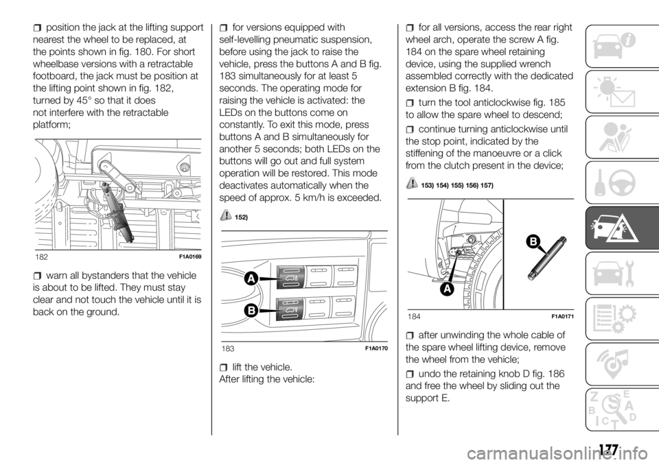
position the jack at the lifting support
nearest the wheel to be replaced, at
the points shown in fig. 180. For short
wheelbase versions with a retractable
footboard, the jack must be position at
the lifting point shown in fig. 182,
turned by 45° so that it does
not interfere with the retractable
platform;
warn all bystanders that the vehicle
is about to be lifted. They must stay
clear and not touch the vehicle until it is
back on the ground.
for versions equipped with
self-levelling pneumatic suspension,
before using the jack to raise the
vehicle, press the buttons A and B fig.
183 simultaneously for at least 5
seconds. The operating mode for
raising the vehicle is activated: the
LEDs on the buttons come on
constantly. To exit this mode, press
buttons A and B simultaneously for
another 5 seconds; both LEDs on the
buttons will go out and full system
operation will be restored. This mode
deactivates automatically when the
speed of approx. 5 km/h is exceeded.
152)
lift the vehicle.
After lifting the vehicle:
for all versions, access the rear right
wheel arch, operate the screw A fig.
184 on the spare wheel retaining
device, using the supplied wrench
assembled correctly with the dedicated
extension B fig. 184.
turn the tool anticlockwise fig. 185
to allow the spare wheel to descend;
continue turning anticlockwise until
the stop point, indicated by the
stiffening of the manoeuvre or a click
from the clutch present in the device;
153) 154) 155) 156) 157)
after unwinding the whole cable of
the spare wheel lifting device, remove
the wheel from the vehicle;
undo the retaining knob D fig. 186
and free the wheel by sliding out the
support E.
182F1A0169
183F1A0170
184F1A0171
177
Page 180 of 304
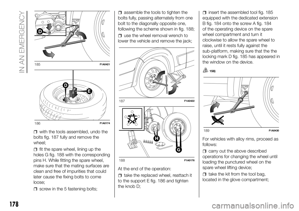
with the tools assembled, undo the
bolts fig. 187 fully and remove the
wheel;
fit the spare wheel, lining up the
holes G fig. 188 with the corresponding
pins H. While fitting the spare wheel,
make sure that the mating surfaces are
clean and free of impurities that could
later cause the fixing bolts to come
loose;
screw in the 5 fastening bolts;
assemble the tools to tighten the
bolts fully, passing alternately from one
bolt to the diagonally opposite one,
following the scheme shown in fig. 188;
use the wheel removal wrench to
lower the vehicle and remove the jack;
At the end of the operation:
take the replaced wheel, reattach it
to the support E fig. 186 and tighten
the knob D;
insert the assembled tool fig. 185
equipped with the dedicated extension
B fig. 184 onto the screw A fig. 184
of the operating device on the spare
wheel compartment and turn it
clockwise to allow the spare wheel to
raise, until it rests fully against the
sub-platform, making sure that the the
locking mark D fig. 185 has appeared in
the window on the device.
158)
For vehicles with alloy rims, proceed as
follows:
carry out the above described
operations for changing the wheel until
loading the punctured wheel on the
spare wheel lifting device;
take the kit from the tool bag,
located in the glove compartment;
185F1A0421
186F1A0174
187F1A0422
G
H
188F1A0176
189F1A0430
178
IN AN EMERGENCY