stop start FIAT FIORINO 2017 Owner handbook (in English)
[x] Cancel search | Manufacturer: FIAT, Model Year: 2017, Model line: FIORINO, Model: FIAT FIORINO 2017Pages: 272, PDF Size: 5.87 MB
Page 32 of 272
the changes already stored by the user (and
confirmed by pressing theSET
button briefly)
will be saved.
From the standard screen, press theSET
button
briefly to start browsing.
Press the
orbuttons to navigate within the
menu.
NoteOnly the reduced menu can be accessed while
the vehicle is moving for safety reasons ("Speed
Beep" setting). Stop the vehicle to access the full
menu.
Adjusting the vehicle interior lighting
This function is available with the dipped beam
headlights on to adjust brightness of the instrument
panel, buttons and radio display.
To adjust the light intensity, proceed as follows:
press the SETbutton briefly to make
the display flash the previously set level;
press theorbutton to set the required
brightness level;
press the SETbutton briefly to go back to the
menu screen or hold the button down to go back
to the standard screen without saving.
Speed limit (Speed Beep)
This function makes it possible to set the vehicle
speed limit (km/h or mph). When this limit isexceeded the driver is immediately alerted (see
“Warning lights and messages” section).
To set the desired speed limit, proceed as follows:
- press theSET
button briefly, the display will
show the wording (Speed Beep);
- press the
orbutton to select speed limit
activation (On) or deactivation (Off );
- if the function is on, press
orbutton to
select the desired speed limit and then pressSET
to confirm.
NoteSetting is possible between 30 and 200 km/h,
or 20 and 125 mph, according to the previously
set unit. See the "Setting the unit of measurement
(Measurement unit)" paragraph described below. The
setting will increase/decrease by 5 units each time
button
/is pressed. Hold down the/
button to automatically increase/decrease the
setting rapidly. Complete the adjustment with single
presses of the button when you approach the desired
value.
- press theSET
button briefly to go back to the
menu screen or hold the button down to go back
to the standard screen without saving.
To cancel the setting, proceed as follows:
- press theSET
button briefly to make the
display flash (On);
- press button
, (Off ) will flash on the display;
- press theSET
button briefly to go back to the
menu screen or hold the button down to go back
to the standard screen without saving.
28
KNOWING YOUR
VEHICLE
SAFETY
STARTING AND
DRIVING
WARNING LIGHTS
AND MESSAGES
IN AN EMERGENCY
SERVICING AND
CARE
TECHNICAL DATA
INDEX
Page 53 of 272
knob A turned to blue section
take the slider B to
turn knob C to the required speed
turn knob D to
INTERNAL AIR RECIRCULATION
ACTIVATION
Take the slider B to
.
It is advisable to switch the internal air recirculation
on while standing in queues or in tunnels to prevent
the introduction of polluted air.
Do not use the function for a long time, particularly
if there are several passengers on board, to prevent
the windows from steaming up.
IMPORTANT The internal air recirculation system
makes it possible to reach the required heating
or cooling conditions more quickly. Do not use the
internal air recirculation function on rainy/cold
days to avoid the possibility of the windows misting.
DEMISTING/DEFROSTING OF HEATED
REAR WINDSCREEN AND DOOR MIRRORS
(for versions/markets, where provided)
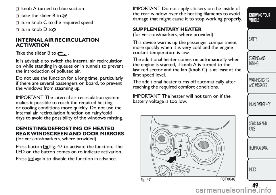
Press button
fig. 47 to activate the function. The
LED on the button comes on to indicate activation.
Press
again to disable the function in advance.IMPORTANT Do not apply stickers on the inside of
the rear window over the heating filaments to avoid
damage that might cause it to stop working properly.
SUPPLEMENTARY HEATER
(for versions/markets, where provided)
This device warms up the passenger compartment
more quickly when it is very cold and the engine
coolant temperature is low.
The additional heater comes on automatically when
the engine is started, if knob A is turned to the
last red sector and the fan (knob C) is at least at the
first speed level.
The additional heater turns off automatically after
reaching the required comfort conditions.
IMPORTANT The heater will not turn on if the
battery voltage is too low.
fig. 47F0T0048
49
KNOWING YOUR
VEHICLE
SAFETY
STARTING AND
DRIVING
WARNING LIGHTS
AND MESSAGES
IN AN EMERGENCY
SERVICING AND
CARE
TECHNICAL DATA
INDEX
Page 56 of 272
turn knob C to
take the slider B to
turn knob D to
press knob C.
Adjusting cooling
Proceed as follows:
take the slider B to
turn knob A rightwards to increase the
temperature
turn knob C leftwards to reduce the fan speed.
DEMISTING/DEFROSTING OF HEATED
REAR WINDSCREEN AND DOOR MIRRORS
(for versions/markets, where provided)
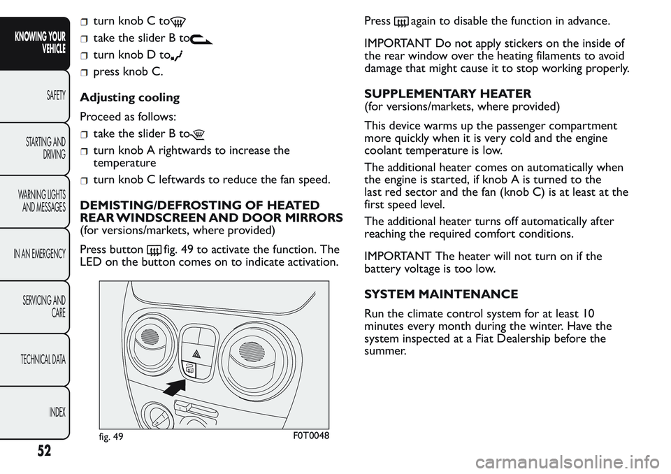
Press button
fig. 49 to activate the function. The
LED on the button comes on to indicate activation.Press
again to disable the function in advance.
IMPORTANT Do not apply stickers on the inside of
the rear window over the heating filaments to avoid
damage that might cause it to stop working properly.
SUPPLEMENTARY HEATER
(for versions/markets, where provided)
This device warms up the passenger compartment
more quickly when it is very cold and the engine
coolant temperature is low.
The additional heater comes on automatically when
the engine is started, if knob A is turned to the
last red sector and the fan (knob C) is at least at the
first speed level.
The additional heater turns off automatically after
reaching the required comfort conditions.
IMPORTANT The heater will not turn on if the
battery voltage is too low.
SYSTEM MAINTENANCE
Run the climate control system for at least 10
minutes every month during the winter. Have the
system inspected at a Fiat Dealership before the
summer.
fig. 49F0T0048
52
KNOWING YOUR
VEHICLE
SAFETY
STARTING AND
DRIVING
WARNING LIGHTS
AND MESSAGES
IN AN EMERGENCY
SERVICING AND
CARE
TECHNICAL DATA
INDEX
Page 57 of 272
EXTERIOR LIGHTS
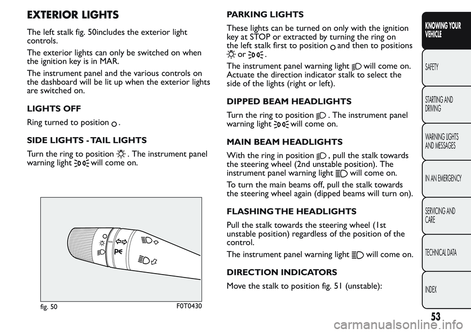
The left stalk fig. 50includes the exterior light
controls.
The exterior lights can only be switched on when
the ignition key is in MAR.
The instrument panel and the various controls on
the dashboard will be lit up when the exterior lights
are switched on.
LIGHTS OFF
Ring turned to position
.
SIDE LIGHTS - TAIL LIGHTS
Turn the ring to position
. The instrument panel
warning light
will come on.PARKING LIGHTS
These lights can be turned on only with the ignition
key at STOP or extracted by turning the ring on
the left stalk first to position
and then to positions
or.
The instrument panel warning light
will come on.
Actuate the direction indicator stalk to select the
side of the lights (right or left).
DIPPED BEAM HEADLIGHTS
Turn the ring to position
. The instrument panel
warning light
will come on.
MAIN BEAM HEADLIGHTS
With the ring in position
, pull the stalk towards
the steering wheel (2nd unstable position). The
instrument panel warning light
will come on.
To turn the main beams off, pull the stalk towards
the steering wheel again (dipped beams will turn on).
FLASHING THE HEADLIGHTS
Pull the stalk towards the steering wheel (1st
unstable position) regardless of the position of the
control.
The instrument panel warning light
will come on.
DIRECTION INDICATORS
Move the stalk to position fig. 51 (unstable):
fig. 50F0T0430
53
KNOWING YOUR
VEHICLE
SAFETY
STARTING AND
DRIVING
WARNING LIGHTS
AND MESSAGES
IN AN EMERGENCY
SERVICING AND
CARE
TECHNICAL DATA
INDEX
Page 58 of 272
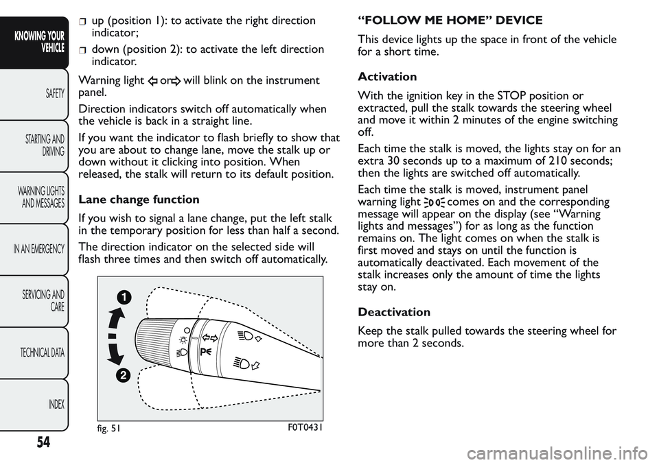
up (position 1): to activate the right direction
indicator;
down (position 2): to activate the left direction
indicator.
Warning light
orwill blink on the instrument
panel.
Direction indicators switch off automatically when
the vehicle is back in a straight line.
If you want the indicator to flash briefly to show that
you are about to change lane, move the stalk up or
down without it clicking into position. When
released, the stalk will return to its default position.
Lane change function
If you wish to signal a lane change, put the left stalk
in the temporary position for less than half a second.
The direction indicator on the selected side will
flash three times and then switch off automatically.“FOLLOW ME HOME” DEVICE
This device lights up the space in front of the vehicle
for a short time.
Activation
With the ignition key in the STOP position or
extracted, pull the stalk towards the steering wheel
and move it within 2 minutes of the engine switching
off.
Each time the stalk is moved, the lights stay on for an
extra 30 seconds up to a maximum of 210 seconds;
then the lights are switched off automatically.
Each time the stalk is moved, instrument panel
warning light
comes on and the corresponding
message will appear on the display (see “Warning
lights and messages”) for as long as the function
remains on. The light comes on when the stalk is
first moved and stays on until the function is
automatically deactivated. Each movement of the
stalk increases only the amount of time the lights
stay on.
Deactivation
Keep the stalk pulled towards the steering wheel for
more than 2 seconds.
fig. 51F0T0431
54
KNOWING YOUR
VEHICLE
SAFETY
STARTING AND
DRIVING
WARNING LIGHTS
AND MESSAGES
IN AN EMERGENCY
SERVICING AND
CARE
TECHNICAL DATA
INDEX
Page 59 of 272
WINDOW CLEANING
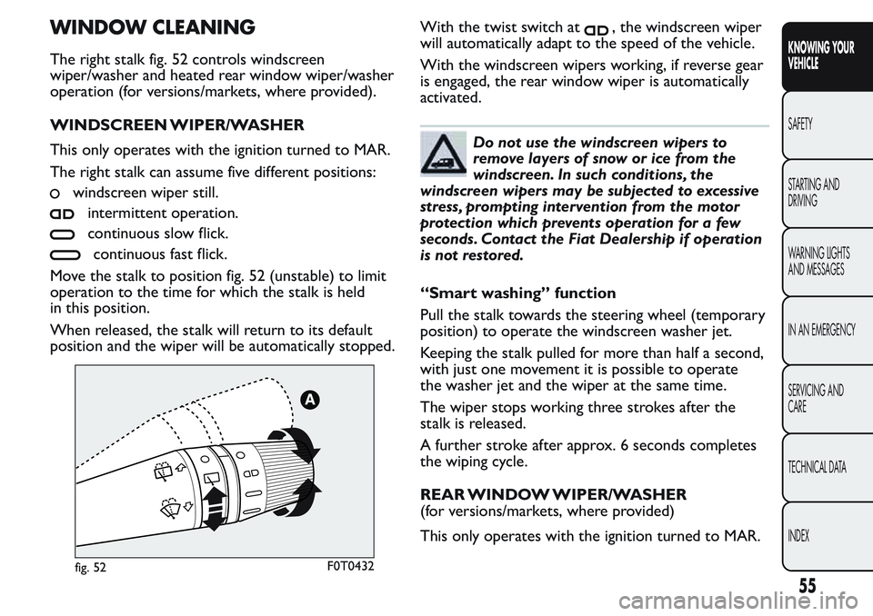
The right stalk fig. 52 controls windscreen
wiper/washer and heated rear window wiper/washer
operation (for versions/markets, where provided).
WINDSCREEN WIPER/WASHER
This only operates with the ignition turned to MAR.
The right stalk can assume five different positions:
windscreen wiper still.
intermittent operation.
continuous slow flick.
continuous fast flick.
Move the stalk to position fig. 52 (unstable) to limit
operation to the time for which the stalk is held
in this position.
When released, the stalk will return to its default
position and the wiper will be automatically stopped.With the twist switch at
, the windscreen wiper
will automatically adapt to the speed of the vehicle.
With the windscreen wipers working, if reverse gear
is engaged, the rear window wiper is automatically
activated.
Do not use the windscreen wipers to
remove layers of snow or ice from the
windscreen. In such conditions, the
windscreen wipers may be subjected to excessive
stress, prompting intervention from the motor
protection which prevents operation for a few
seconds. Contact the Fiat Dealership if operation
is not restored.
“Smart washing” function
Pull the stalk towards the steering wheel (temporary
position) to operate the windscreen washer jet.
Keeping the stalk pulled for more than half a second,
with just one movement it is possible to operate
the washer jet and the wiper at the same time.
The wiper stops working three strokes after the
stalk is released.
A further stroke after approx. 6 seconds completes
the wiping cycle.
REAR WINDOW WIPER/WASHER
(for versions/markets, where provided)
This only operates with the ignition turned to MAR.
fig. 52F0T0432
55
KNOWING YOUR
VEHICLE
SAFETY
STARTING AND
DRIVING
WARNING LIGHTS
AND MESSAGES
IN AN EMERGENCY
SERVICING AND
CARE
TECHNICAL DATA
INDEX
Page 60 of 272
Activation
Turn the ring to
to operate the rear window
wiper as follows:
intermittent operation if the windscreen wiper is
off;
in synchronous mode (at half the speed of the
windscreen wiper) when the windscreen wiper
is on;
in continuous mode with reverse gear engaged
and the control active.
With the windscreen wiper on and reverse gear
engaged, rear window wiping will be continuous.
Pushing the stalk towards the dashboard (temporary
position) the rear window washer jet will activate.
Keeping the stalk pushed for more than half a second
also the rear window wiper will activate. Releasing
the stalk will activate the smart washing function, as
described for the windscreen wiper.
Deactivation
The function stops when the stalk is released.
Do not use the rear window wiper to
removelayersofsnoworice.In
such conditions, the wiper may be
subjected to excessive stress and the motor
protection, which prevents operation for a few
seconds, may intervene. Contact the Fiat
Dealership if operation is not restored.
CRUISE CONTROL
(for versions/markets, where provided)
This is an electronic driving aid that allows you to
drive at a speed of above 30 km/h on long and
straight dry roads with few driving changes (e.g.
motorways) at a preset speed without having to
press the accelerator pedal. Therefore it is not
recommended to use this device on extra-urban
roads with traffic. Do not use it in town.
Switching the device on
When the device is activated, light
comes on
together with the relevant message on the
instrument panel (for versions/markets, where
provided).
The function cannot be turned on in first gear or
reverse. It is advisable to use the function in fourth
gear or higher.
When travelling downhill with the device engaged,
the vehicle speed may exceed the stored setting.
Memorizing vehicle speed
Proceed as follows:
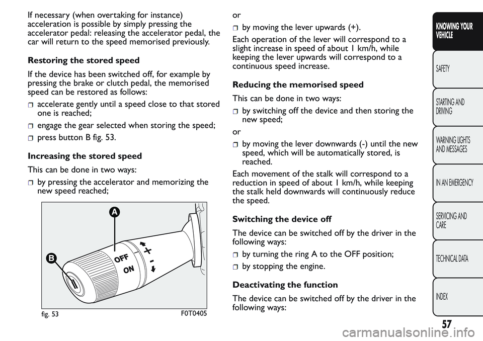
turn ring nut A fig. 53 to the ON position and
press the accelerator pedal so that the vehicle
reaches the desired speed;
move the stalk upwards (+) for at least one
second, then release it. The vehicle speed is now
stored and you can therefore release the
accelerator pedal.
56
KNOWING YOUR
VEHICLE
SAFETY
STARTING AND
DRIVING
WARNING LIGHTS
AND MESSAGES
IN AN EMERGENCY
SERVICING AND
CARE
TECHNICAL DATA
INDEX
Page 61 of 272
If necessary (when overtaking for instance)
acceleration is possible by simply pressing the
accelerator pedal: releasing the accelerator pedal, the
car will return to the speed memorised previously.
Restoring the stored speed
If the device has been switched off, for example by
pressing the brake or clutch pedal, the memorised
speed can be restored as follows:
accelerate gently until a speed close to that stored
one is reached;
engage the gear selected when storing the speed;
press button B fig. 53.
Increasing the stored speed
This can be done in two ways:
by pressing the accelerator and memorizing the
new speed reached;or
by moving the lever upwards (+).
Each operation of the lever will correspond to a
slight increase in speed of about 1 km/h, while
keeping the lever upwards will correspond to a
continuous speed increase.
Reducing the memorised speed
This can be done in two ways:
by switching off the device and then storing the
new speed;
or
by moving the lever downwards (-) until the new
speed, which will be automatically stored, is
reached.
Each movement of the stalk will correspond to a
reduction in speed of about 1 km/h, while keeping
the stalk held downwards will continuously reduce
the speed.
Switching the device off
The device can be switched off by the driver in the
following ways:
by turning the ring A to the OFF position;
by stopping the engine.
Deactivating the function
The device can be switched off by the driver in the
following ways:
fig. 53F0T0405
57
KNOWING YOUR
VEHICLE
SAFETY
STARTING AND
DRIVING
WARNING LIGHTS
AND MESSAGES
IN AN EMERGENCY
SERVICING AND
CARE
TECHNICAL DATA
INDEX
Page 64 of 272
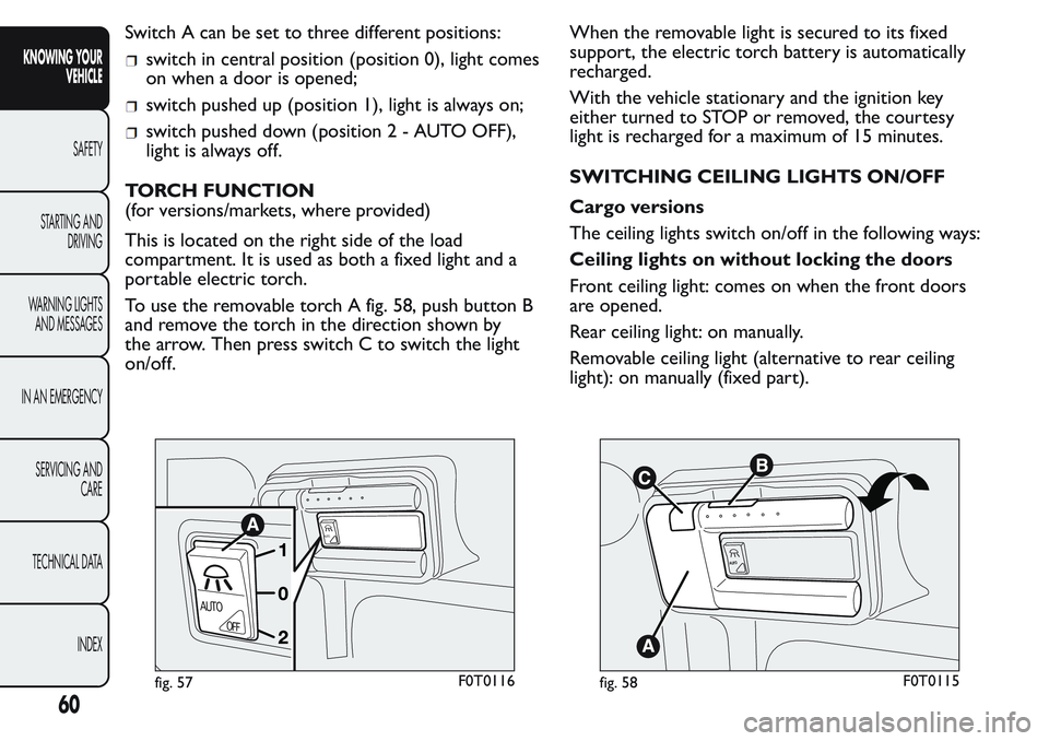
Switch A can be set to three different positions:
switch in central position (position 0), light comes
on when a door is opened;
switch pushed up (position 1), light is always on;
switch pushed down (position2-AUTOOFF),
light is always off.
TORCH FUNCTION
(for versions/markets, where provided)
This is located on the right side of the load
compartment. It is used as both a fixed light and a
portable electric torch.
To use the removable torch A fig. 58, push button B
and remove the torch in the direction shown by
the arrow. Then press switch C to switch the light
on/off.When the removable light is secured to its fixed
support, the electric torch battery is automatically
recharged.
With the vehicle stationary and the ignition key
either turned to STOP or removed, the courtesy
light is recharged for a maximum of 15 minutes.
SWITCHING CEILING LIGHTS ON/OFF
Cargo versions
The ceiling lights switch on/off in the following ways:
Ceiling lights on without locking the doors
Front ceiling light: comes on when the front doors
are opened.
Rear ceiling light: on manually.
Removable ceiling light (alternative to rear ceiling
light): on manually (fixed part).
AUTO
AUTO
OFF
fig. 57F0T0116
A
UT
O
fig. 58F0T0115
60
KNOWING YOUR
VEHICLE
SAFETY
STARTING AND
DRIVING
WARNING LIGHTS
AND MESSAGES
IN AN EMERGENCY
SERVICING AND
CARE
TECHNICAL DATA
INDEX
Page 72 of 272
Make sure that the right sliding side door
is all closed before refuelling to prevent
damage to the door and to the sliding
locking system with fuel filler cap open, activated
during refuelling operations.
WARNING
The right sliding side door cannot be
opened with the fuel flap open during
refuelling.
On Cargo versions, the sliding side door is fitted
with a spring-loaded latch that stops the door from
opening any further. To lock it, simply push the
door as far as it will go; to unlock it, pull forward
firmly.
In any case, make sure that the door is properly
hooked to the system which keeps the door fully
open.
WARNING
Do not leave the sliding side door open
when the vehicle is parked on a
gradient . A knock could release the latch leaving
the door free to move.
WARNING
Before leaving the vehicle parked with
sliding doors open, always check that
the latch is engaged.
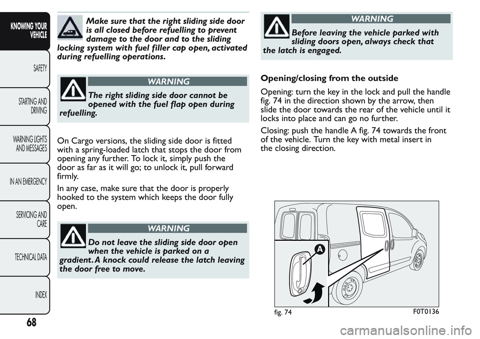
Opening/closing from the outside
Opening: turn the key in the lock and pull the handle
fig. 74 in the direction shown by the arrow, then
slide the door towards the rear of the vehicle until it
locks into place and can go no further.
Closing: push the handle A fig. 74 towards the front
of the vehicle. Turn the key with metal insert in
the closing direction.
fig. 74F0T0136
68
KNOWING YOUR
VEHICLE
SAFETY
STARTING AND
DRIVING
WARNING LIGHTS
AND MESSAGES
IN AN EMERGENCY
SERVICING AND
CARE
TECHNICAL DATA
INDEX