technical data FIAT FIORINO 2017 Owner handbook (in English)
[x] Cancel search | Manufacturer: FIAT, Model Year: 2017, Model line: FIORINO, Model: FIAT FIORINO 2017Pages: 272, PDF Size: 5.87 MB
Page 76 of 272
WINDOWS
FRONT ELECTRIC WINDOWS
(for versions/markets, where provided)
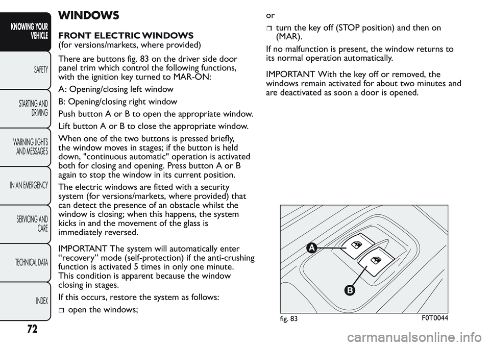
There are buttons fig. 83 on the driver side door
panel trim which control the following functions,
with the ignition key turned to MAR-ON:
A: Opening/closing left window
B: Opening/closing right window
Push button A or B to open the appropriate window.
Lift button A or B to close the appropriate window.
When one of the two buttons is pressed briefly,
the window moves in stages; if the button is held
down, "continuous automatic" operation is activated
both for closing and opening. Press button A or B
again to stop the window in its current position.
The electric windows are fitted with a security
system (for versions/markets, where provided) that
can detect the presence of an obstacle whilst the
window is closing; when this happens, the system
kicks in and the movement of the glass is
immediately reversed.
IMPORTANT The system will automatically enter
“recovery” mode (self-protection) if the anti-crushing
function is activated 5 times in only one minute.
This condition is apparent because the window
closing in stages.
If this occurs, restore the system as follows:
open the windows;or
turn the key off (STOP position) and then on
(MAR).
If no malfunction is present, the window returns to
its normal operation automatically.
IMPORTANT With the key off or removed, the
windows remain activated for about two minutes and
are deactivated as soon a door is opened.
fig. 83F0T0044
72
KNOWING YOUR
VEHICLE
SAFETY
STARTING AND
DRIVING
WARNING LIGHTS
AND MESSAGES
IN AN EMERGENCY
SERVICING AND
CARE
TECHNICAL DATA
INDEX
Page 77 of 272
WARNING
Improper use of the electric windows
can be dangerous. Before and during
their operation ensure that passengers are not
at risk from the moving glass, either by personal
objects caught in the mechanism or struck by
it directly. When leaving the car, always remove
the ignition key to avoid the risk of injury due
to accidental operation of the electric
windows.
MANUAL FRONT WINDOWS
On some versions, the front windows are opened
and closed manually.
Wind the handle to open/close.
LUGGAGE COMPARTMENT
EMERGENCY OPENING FROM THE INSIDE
In the event of an emergency, you can open the
tailgate from inside as follows:
open the sliding side door and lower the backrest
of the rear seat to gain access to the boot (Combi
versions);
or
open the sliding side door (Cargo versions);
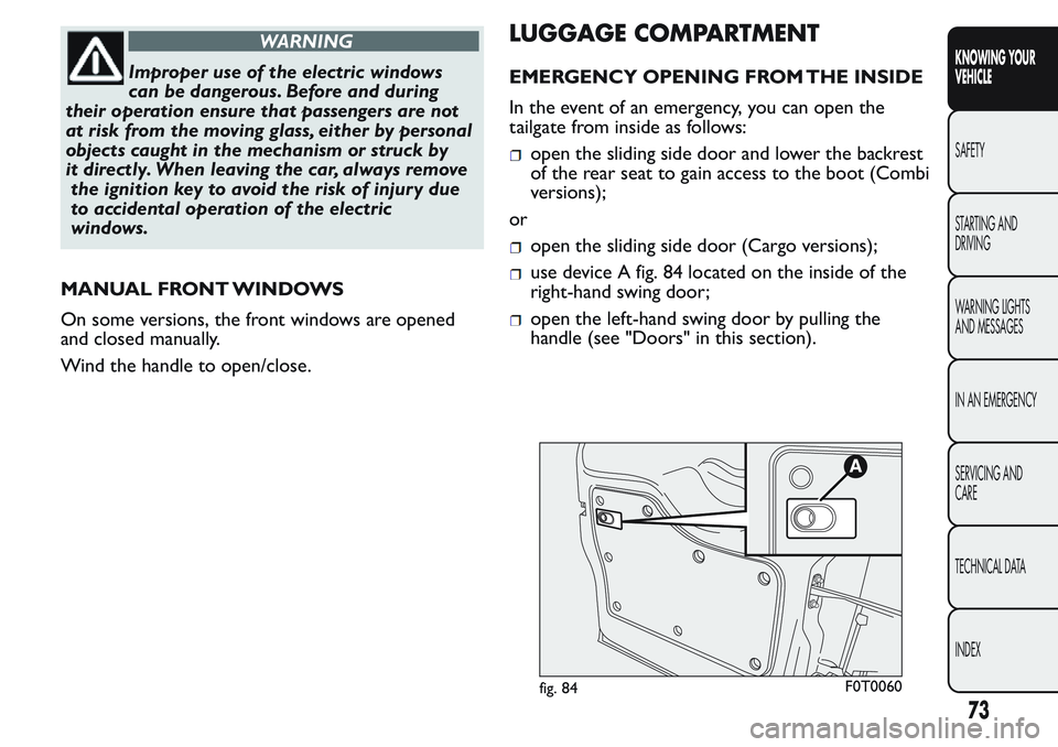
use device A fig. 84 located on the inside of the
right-hand swing door;
open the left-hand swing door by pulling the
handle (see "Doors" in this section).
fig. 84F0T0060
73
KNOWING YOUR
VEHICLE
SAFETY
STARTING AND
DRIVING
WARNING LIGHTS
AND MESSAGES
IN AN EMERGENCY
SERVICING AND
CARE
TECHNICAL DATA
INDEX
Page 78 of 272
WARNING
If you are travelling in areas with few
filling stations and you want to
transport fuel in a spare tank, comply with the
law by using only an approved, suitably secured
tank. In the event of a collision the fire risk is
increased all the same.
WARNING
Never exceed the maximum allowed
load in the boot (see "Technical
Specifications" section). Also make sure that the
objects you place in the luggage compar tment
have been properly secured, to avoid them from
being thrown forward consequent to sudden
braking and injuring your passengers.
REMOVING THE PARCEL SHELF (Combi
versions)
(for versions/markets, where provided)
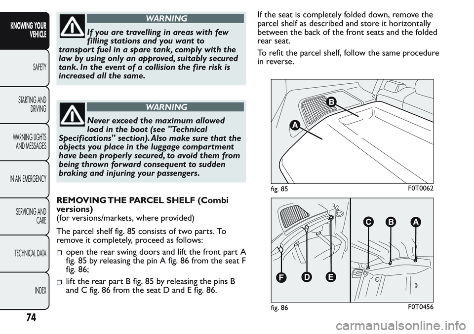
The parcel shelf fig. 85 consists of two parts. To
remove it completely, proceed as follows:
open the rear swing doors and lift the front part A
fig. 85 by releasing the pin A fig. 86 from the seat F
fig. 86;
lift the rear part B fig. 85 by releasing the pins B
and C fig. 86 from the seat D and E fig. 86.If the seat is completely folded down, remove the
parcel shelf as described and store it horizontally
between the back of the front seats and the folded
rear seat.
To refit the parcel shelf, follow the same procedure
in reverse.
fig. 85F0T0062
fig. 86F0T0456
74
KNOWING YOUR
VEHICLE
SAFETY
STARTING AND
DRIVING
WARNING LIGHTS
AND MESSAGES
IN AN EMERGENCY
SERVICING AND
CARE
TECHNICAL DATA
INDEX
Page 79 of 272
WARNING
You must not use the folded rear seat to
carr y luggage.The load could be thrown
forward into the backrest of the front seats,
seriously injuring the occupants.
EXTENDING THE BOOT
Proceed as follows:
open the rear doors and remove the parcel shelf
(as described previously);
completely lower the rear seat head restraints;
move the seat belt to the side, making sure that it
is fully extended and not twisted;
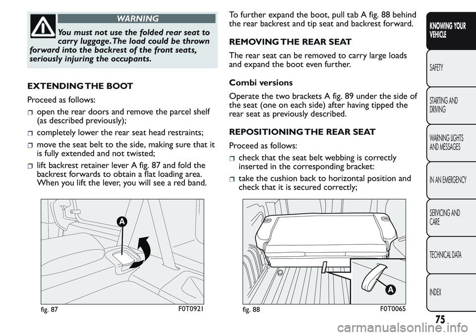
lift backrest retainer lever A fig. 87 and fold the
backrest forwards to obtain a flat loading area.
When you lift the lever, you will see a red band.To further expand the boot, pull tab A fig. 88 behind
the rear backrest and tip seat and backrest forward.
REMOVING THE REAR SEAT
The rear seat can be removed to carry large loads
and expand the boot even further.
Combi versions
Operate the two brackets A fig. 89 under the side of
the seat (one on each side) after having tipped the
rear seat as previously described.
REPOSITIONING THE REAR SEAT
Proceed as follows:check that the seat belt webbing is correctly
inserted in the corresponding bracket:
take the cushion back to horizontal position and
check that it is secured correctly;
fig. 87F0T0921fig. 88F0T0065
75
KNOWING YOUR
VEHICLE
SAFETY
STARTING AND
DRIVING
WARNING LIGHTS
AND MESSAGES
IN AN EMERGENCY
SERVICING AND
CARE
TECHNICAL DATA
INDEX
Page 80 of 272
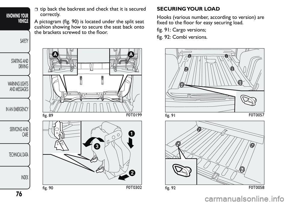
tip back the backrest and check that it is secured
correctly.
A pictogram (fig. 90) is located under the split seat
cushion showing how to secure the seat back onto
the brackets screwed to the floor.SECURING YOUR LOAD
Hooks (various number, according to version) are
fixed to the floor for easy securing load.
fig. 91: Cargo versions;
fig. 92: Combi versions.
fig. 89F0T0199
fig. 90F0T0302
fig. 91F0T0057
fig. 92F0T0058
76
KNOWING YOUR
VEHICLE
SAFETY
STARTING AND
DRIVING
WARNING LIGHTS
AND MESSAGES
IN AN EMERGENCY
SERVICING AND
CARE
TECHNICAL DATA
INDEX
Page 81 of 272
BONNET
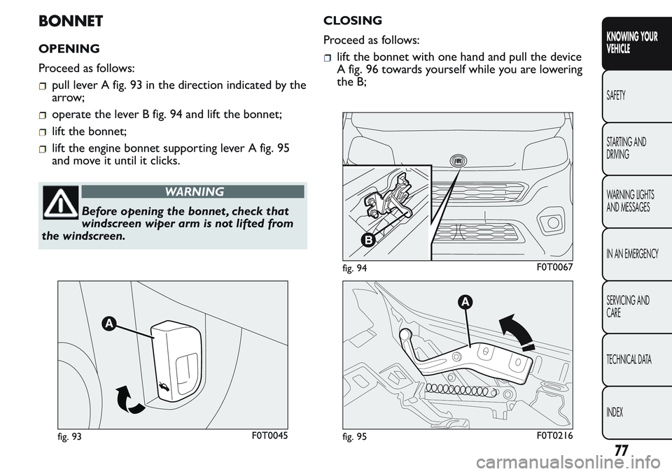
OPENING
Proceed as follows:
pull lever A fig. 93 in the direction indicated by the
arrow;
operate the lever B fig. 94 and lift the bonnet;
lift the bonnet;
lift the engine bonnet supporting lever A fig. 95
and move it until it clicks.
WARNING
Before opening the bonnet , check that
windscreen wiper arm is not lifted from
the windscreen.CLOSING
Proceed as follows:
lift the bonnet with one hand and pull the device
A fig. 96 towards yourself while you are lowering
the B;
fig. 93F0T0045
fig. 94F0T0067
fig. 95F0T0216
77
KNOWING YOUR
VEHICLE
SAFETY
STARTING AND
DRIVING
WARNING LIGHTS
AND MESSAGES
IN AN EMERGENCY
SERVICING AND
CARE
TECHNICAL DATA
INDEX
Page 82 of 272
lower the bonnet to approximately 20 centimetres
from the engine compartment and let it drop.
Make sure that the bonnet is completely closed
and not only fastened by the safety catch by trying
to open it. If it is not perfectly closed, do not try
to press the bonnet lid down but open it and
repeat the procedure.
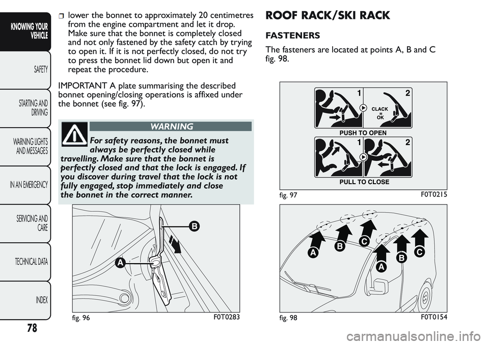
IMPORTANT A plate summarising the described
bonnet opening/closing operations is affixed under
the bonnet (see fig. 97).
WARNING
For safety reasons, the bonnet must
always be perfectly closed while
travelling. Make sure that the bonnet is
perfectly closed and that the lock is engaged. If
you discover during travel that the lock is not
fully engaged, stop immediately and close
the bonnet in the correct manner.
ROOF RACK/SKI RACK
FASTENERS
The fasteners are located at points A, B and C
fig. 98.
fig. 96F0T0283
fig. 97F0T0215
fig. 98F0T0154
78
KNOWING YOUR
VEHICLE
SAFETY
STARTING AND
DRIVING
WARNING LIGHTS
AND MESSAGES
IN AN EMERGENCY
SERVICING AND
CARE
TECHNICAL DATA
INDEX
Page 83 of 272
ROOF RAILS
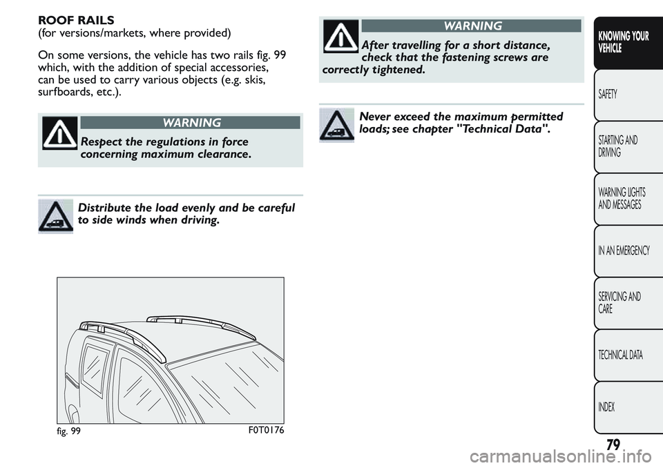
(for versions/markets, where provided)
On some versions, the vehicle has two rails fig. 99
which, with the addition of special accessories,
can be used to carry various objects (e.g. skis,
surfboards, etc.).
WARNING
Respect the regulations in force
concerning maximum clearance.
Distribute the load evenly and be careful
to side winds when driving.
WARNING
After travelling for a short distance,
check that the fastening screws are
correctly tightened.
Never exceed the maximum permitted
loads; see chapter "Technical Data".
fig. 99F0T0176
79
KNOWING YOUR
VEHICLE
SAFETY
STARTING AND
DRIVING
WARNING LIGHTS
AND MESSAGES
IN AN EMERGENCY
SERVICING AND
CARE
TECHNICAL DATA
INDEX
Page 84 of 272
HEADLIGHTS
LIGHT BEAM DIRECTION
The correct direction of the headlights is essential
for the comfort and safety of the driver and other
road users. To ensure the best visibility when
travelling with the headlights on, the headlight
alignment must be correct. Contact a Fiat Dealership
to have the direction checked and, if necessary,
adjusted.
HEADLIGHT ALIGNMENT CORRECTOR
This device works with the ignition key in the MAR
position and the dipped headlights on.
The vehicle tilts backwards when it is laden, raising
the beam.
The beams must therefore be aimed again in this
case.Adjusting headlight alignment
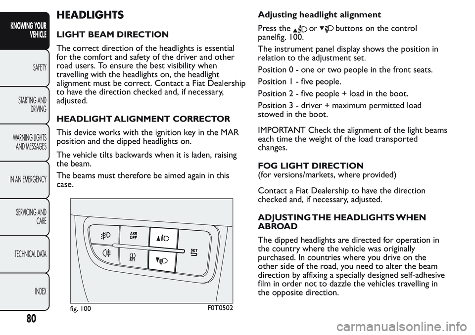
Press theorbuttons on the control
panelfig. 100.
The instrument panel display shows the position in
relation to the adjustment set.
Position 0 - one or two people in the front seats.
Position1-fivepeople.
Position2-fivepeople + load in the boot.
Position 3 - driver + maximum permitted load
stowed in the boot.
IMPORTANT Check the alignment of the light beams
each time the weight of the load transported
changes.
FOG LIGHT DIRECTION
(for versions/markets, where provided)
Contact a Fiat Dealership to have the direction
checked and, if necessary, adjusted.
ADJUSTING THE HEADLIGHTS WHEN
ABROAD
The dipped headlights are directed for operation in
the country where the vehicle was originally
purchased. In countries where you drive on the
other side of the road, you need to alter the beam
direction by affixing a specially designed self-adhesive
film in order not to dazzle the vehicles travelling in
the opposite direction.
fig. 100F0T0502
80
KNOWING YOUR
VEHICLE
SAFETY
STARTING AND
DRIVING
WARNING LIGHTS
AND MESSAGES
IN AN EMERGENCY
SERVICING AND
CARE
TECHNICAL DATA
INDEX
Page 85 of 272
ABS SYSTEM
This is an integral part of the braking system, which
prevents one or more wheels from locking or
slipping regardless of the road surface conditions and
braking intensity, giving the best control during
emergency braking.
The EBD system (Electronic Braking Force
Distribution) completes the system, allowing the
brake force to be distributed between the front and
rear wheels.
IMPORTANT For maximum efficiency of the braking
system, a bedding-in period of about 500 km is
needed: during this period it is better to avoid sharp,
repeated and prolonged braking.
SYSTEM INTERVENTION
The driver can tell the ABS system has come into
action because the brake pedal pulsates slightly and
the system gets noisier: it means that the vehicle
speed should be altered to suit the type of road
surface.
MECHANICAL BRAKE ASSIST (emergency
braking assistance)
(for versions/markets, where provided)
This system, which cannot be deactivated, recognises
emergency braking conditions (according to the
brake pedal operation speed) and provides an
additional hydraulic braking pressure to support thatprovided by the driver. This allows faster and more
powerful operation of the braking system.
IMPORTANT When the Mechanical Brake Assist is
activated, noises may be heard from the system. This
is normal. In any case, while braking keep the brake
pedal firmly depressed.
WARNING
When the ABS cuts in and you feel the
brake pedal pulsating, do not remove
your foot , but keep the pedal pushed down; in
doing so you, will stop in the shortest distance
possible under the road conditions at the time.
WARNING
If the ABS cuts in, it is a sign that the
grip between tyre and the road surface
has reached the limit : you must slow down to
match the speed to the road grip available.
WARNING
The ABS gets the most from the
available grip, but it cannot improve it ;
you should therefore take every care when
driving on slippery surfaces and not take
unnecessary risks.
81
KNOWING YOUR
VEHICLE
SAFETY
STARTING AND
DRIVING
WARNING LIGHTS
AND MESSAGES
IN AN EMERGENCY
SERVICING AND
CARE
TECHNICAL DATA
INDEX