ESP FIAT FIORINO 2017 Owner handbook (in English)
[x] Cancel search | Manufacturer: FIAT, Model Year: 2017, Model line: FIORINO, Model: FIAT FIORINO 2017Pages: 272, PDF Size: 5.87 MB
Page 2 of 272

Noi che abbiamo ideato, progettato e costruito il tuo veicolo,
lo conosciamo davvero in ogni singolo dettaglio e componente. Nelle officine autorizzate Fiat Professional Service
trovi tecnici formati direttamente da noi che ti offrono qualità e pr\
ofessionalità in tutti gli interventi di manutenzione. Le officine Fiat Professional sono sempre al tuo fianco pe\
r la manutenzione periodica, i controlli di stagione e per i consigli pratici dei nostri esperti.
Con i Ricambi Originali Fiat Professional, mantieni nel tempo le caratte\
ristiche di affidabilità, comfort e performance per cui hai scelto il tuo nuovo veicolo.
Chiedi sempre i Ricambi Originali dei componenti che utilizziamo per cos\
truire le nostre auto e che ti raccomandiamo perché sono il risultato del nostro costante impegno ne\
lla ricerca e nello sviluppo di tecnologie sempre più innovative.
Per tutti questi motivi affidati ai Ricambi Originali:
i soli appositamente progettati da Fiat Professional per il tuo veicolo.
SICUREZZA:
SISTEMA FRENANTEECOLOGIA: FILTRI ANTIPARTICOLATO, MANUTENZIONE CLIMATIZZATORECOMFORT:
SOSPENSIONI E TERGICRISTALLIPERFORMANCE:
CANDELE, INIETTORI E BATTERIELINEA ACCESSORI:
BARRE PORTA TUTTO, CERCHI
PERCHÈ SCEGLIERE
RICAMBI ORIGINALI
COP FULL BACK LUM IT.qxp_500 UM ITA 23/02/16 09:51 Pagina 2
Page 6 of 272
READ THIS CAREFULLY!
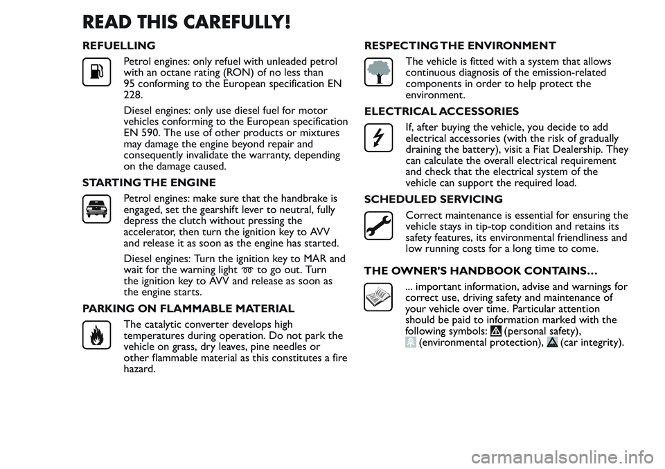
REFUELLING
Petrol engines: only refuel with unleaded petrol
with an octane rating (RON) of no less than
95 conforming to the European specification EN
228.
Diesel engines: only use diesel fuel for motor
vehicles conforming to the European specification
EN 590. The use of other products or mixtures
may damage the engine beyond repair and
consequently invalidate the warranty, depending
on the damage caused.
STARTING THE ENGINE
Petrol engines: make sure that the handbrake is
engaged, set the gearshift lever to neutral, fully
depress the clutch without pressing the
accelerator, then turn the ignition key to AVV
and release it as soon as the engine has started.
Diesel engines: Turn the ignition key to MAR and
wait for the warning light
to go out. Turn
the ignition key to AVV and release as soon as
the engine starts.
PARKING ON FLAMMABLE MATERIAL
The catalytic converter develops high
temperatures during operation. Do not park the
vehicle on grass, dry leaves, pine needles or
other flammable material as this constitutes a fire
hazard.RESPECTING THE ENVIRONMENT
The vehicle is fitted with a system that allows
continuous diagnosis of the emission-related
components in order to help protect the
environment.
ELECTRICAL ACCESSORIES
If, after buying the vehicle, you decide to add
electrical accessories (with the risk of gradually
draining the battery), visit a Fiat Dealership. They
can calculate the overall electrical requirement
and check that the electrical system of the
vehicle can support the required load.
SCHEDULED SERVICING
Correct maintenance is essential for ensuring the
vehicle stays in tip-top condition and retains its
safety features, its environmental friendliness and
low running costs for a long time to come.
THE OWNER'S HANDBOOK CONTAINS…
... important information, advise and warnings for
correct use, driving safety and maintenance of
your vehicle over time. Particular attention
should be paid to information marked with the
following symbols:
(personal safety),(environmental protection),(car integrity).
Page 15 of 272
IMPORTANT During this operation the window
ant-crush safety system is inhibited.
Unlocking/locking the load compartment
from inside the vehicle (Cargo version)
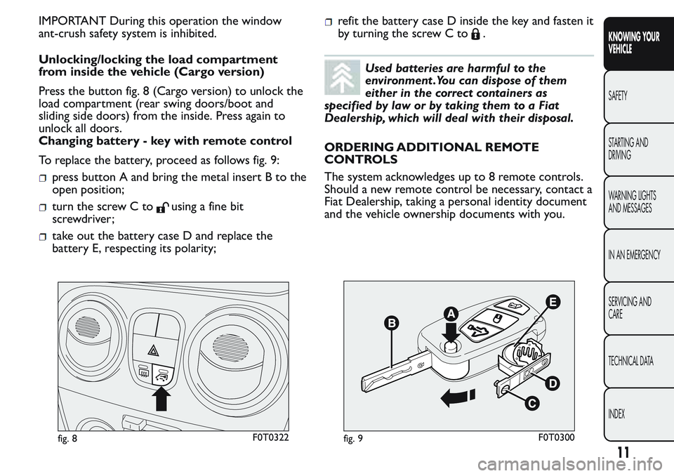
Press the button fig. 8 (Cargo version) to unlock the
load compartment (rear swing doors/boot and
sliding side doors) from the inside. Press again to
unlock all doors.
Changing battery - key with remote control
To replace the battery, proceed as follows fig. 9:
press button A and bring the metal insert B to the
open position;
turn the screw C tousing a fine bit
screwdriver;
take out the battery case D and replace the
battery E, respecting its polarity;
refit the battery case D inside the key and fasten it
by turning the screw C to
.
Used batteries are harmful to the
environment .You can dispose of them
either in the correct containers as
specified by law or by taking them to a Fiat
Dealership, which will deal with their disposal.
ORDERING ADDITIONAL REMOTE
CONTROLS
The system acknowledges up to 8 remote controls.
Should a new remote control be necessary, contact a
Fiat Dealership, taking a personal identity document
and the vehicle ownership documents with you.
fig. 8F0T0322fig. 9F0T0300
11
KNOWING YOUR
VEHICLE
SAFETY
STARTING AND
DRIVING
WARNING LIGHTS
AND MESSAGES
IN AN EMERGENCY
SERVICING AND
CARE
TECHNICAL DATA
INDEX
Page 58 of 272
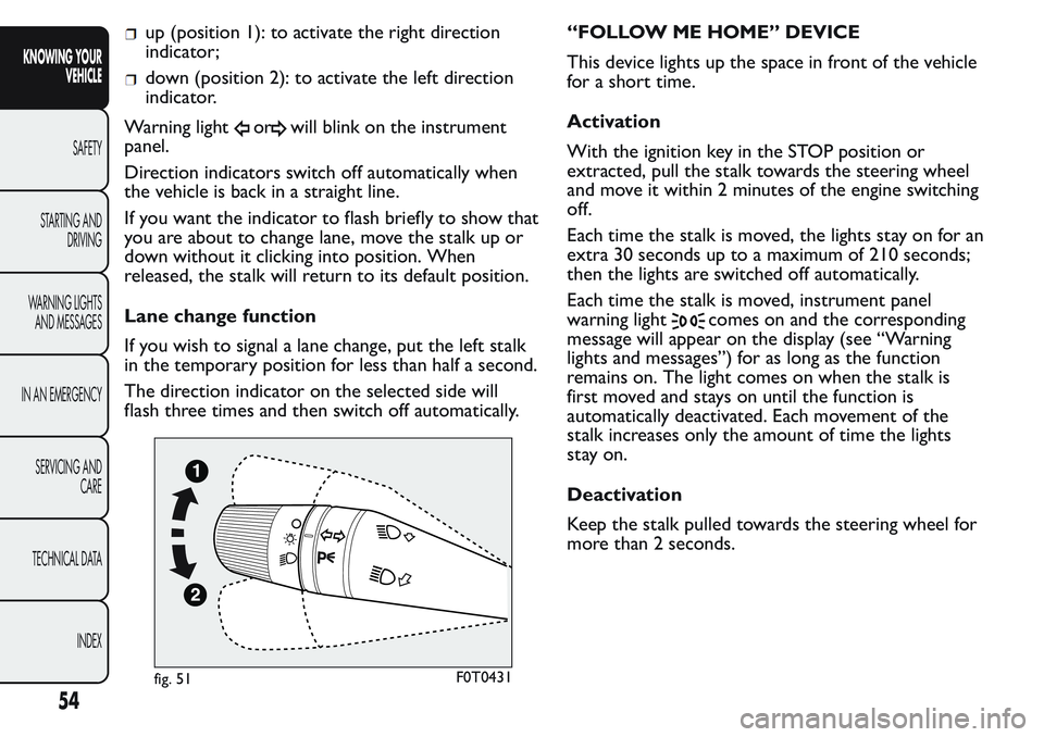
up (position 1): to activate the right direction
indicator;
down (position 2): to activate the left direction
indicator.
Warning light
orwill blink on the instrument
panel.
Direction indicators switch off automatically when
the vehicle is back in a straight line.
If you want the indicator to flash briefly to show that
you are about to change lane, move the stalk up or
down without it clicking into position. When
released, the stalk will return to its default position.
Lane change function
If you wish to signal a lane change, put the left stalk
in the temporary position for less than half a second.
The direction indicator on the selected side will
flash three times and then switch off automatically.“FOLLOW ME HOME” DEVICE
This device lights up the space in front of the vehicle
for a short time.
Activation
With the ignition key in the STOP position or
extracted, pull the stalk towards the steering wheel
and move it within 2 minutes of the engine switching
off.
Each time the stalk is moved, the lights stay on for an
extra 30 seconds up to a maximum of 210 seconds;
then the lights are switched off automatically.
Each time the stalk is moved, instrument panel
warning light
comes on and the corresponding
message will appear on the display (see “Warning
lights and messages”) for as long as the function
remains on. The light comes on when the stalk is
first moved and stays on until the function is
automatically deactivated. Each movement of the
stalk increases only the amount of time the lights
stay on.
Deactivation
Keep the stalk pulled towards the steering wheel for
more than 2 seconds.
fig. 51F0T0431
54
KNOWING YOUR
VEHICLE
SAFETY
STARTING AND
DRIVING
WARNING LIGHTS
AND MESSAGES
IN AN EMERGENCY
SERVICING AND
CARE
TECHNICAL DATA
INDEX
Page 61 of 272
If necessary (when overtaking for instance)
acceleration is possible by simply pressing the
accelerator pedal: releasing the accelerator pedal, the
car will return to the speed memorised previously.
Restoring the stored speed
If the device has been switched off, for example by
pressing the brake or clutch pedal, the memorised
speed can be restored as follows:
accelerate gently until a speed close to that stored
one is reached;
engage the gear selected when storing the speed;
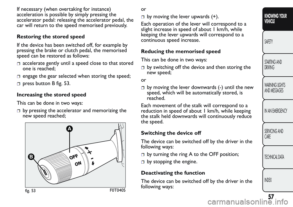
press button B fig. 53.
Increasing the stored speed
This can be done in two ways:
by pressing the accelerator and memorizing the
new speed reached;or
by moving the lever upwards (+).
Each operation of the lever will correspond to a
slight increase in speed of about 1 km/h, while
keeping the lever upwards will correspond to a
continuous speed increase.
Reducing the memorised speed
This can be done in two ways:
by switching off the device and then storing the
new speed;
or
by moving the lever downwards (-) until the new
speed, which will be automatically stored, is
reached.
Each movement of the stalk will correspond to a
reduction in speed of about 1 km/h, while keeping
the stalk held downwards will continuously reduce
the speed.
Switching the device off
The device can be switched off by the driver in the
following ways:
by turning the ring A to the OFF position;
by stopping the engine.
Deactivating the function
The device can be switched off by the driver in the
following ways:
fig. 53F0T0405
57
KNOWING YOUR
VEHICLE
SAFETY
STARTING AND
DRIVING
WARNING LIGHTS
AND MESSAGES
IN AN EMERGENCY
SERVICING AND
CARE
TECHNICAL DATA
INDEX
Page 79 of 272
WARNING
You must not use the folded rear seat to
carr y luggage.The load could be thrown
forward into the backrest of the front seats,
seriously injuring the occupants.
EXTENDING THE BOOT
Proceed as follows:
open the rear doors and remove the parcel shelf
(as described previously);
completely lower the rear seat head restraints;
move the seat belt to the side, making sure that it
is fully extended and not twisted;
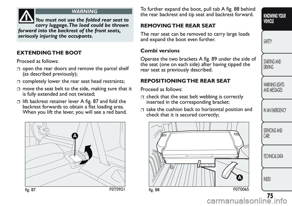
lift backrest retainer lever A fig. 87 and fold the
backrest forwards to obtain a flat loading area.
When you lift the lever, you will see a red band.To further expand the boot, pull tab A fig. 88 behind
the rear backrest and tip seat and backrest forward.
REMOVING THE REAR SEAT
The rear seat can be removed to carry large loads
and expand the boot even further.
Combi versions
Operate the two brackets A fig. 89 under the side of
the seat (one on each side) after having tipped the
rear seat as previously described.
REPOSITIONING THE REAR SEAT
Proceed as follows:check that the seat belt webbing is correctly
inserted in the corresponding bracket:
take the cushion back to horizontal position and
check that it is secured correctly;
fig. 87F0T0921fig. 88F0T0065
75
KNOWING YOUR
VEHICLE
SAFETY
STARTING AND
DRIVING
WARNING LIGHTS
AND MESSAGES
IN AN EMERGENCY
SERVICING AND
CARE
TECHNICAL DATA
INDEX
Page 83 of 272
ROOF RAILS
(for versions/markets, where provided)
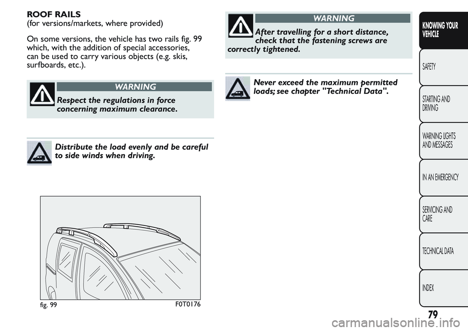
On some versions, the vehicle has two rails fig. 99
which, with the addition of special accessories,
can be used to carry various objects (e.g. skis,
surfboards, etc.).
WARNING
Respect the regulations in force
concerning maximum clearance.
Distribute the load evenly and be careful
to side winds when driving.
WARNING
After travelling for a short distance,
check that the fastening screws are
correctly tightened.
Never exceed the maximum permitted
loads; see chapter "Technical Data".
fig. 99F0T0176
79
KNOWING YOUR
VEHICLE
SAFETY
STARTING AND
DRIVING
WARNING LIGHTS
AND MESSAGES
IN AN EMERGENCY
SERVICING AND
CARE
TECHNICAL DATA
INDEX
Page 88 of 272
WARNING
The capability of the ESC system must
never be tested irresponsibly and
dangerously, in such a way as to compromise
personal safety and the safety of others.
HILL HOLDER SYSTEM
(for versions/markets, where provided)
This system is an integral part of the ESC system and
facilitates starting on slopes.
It is automatically activated in the following
conditions:
uphill: vehicle stationary on a road with a gradient
higher than 5%, engine running, brake pedal
pressed and gearbox in neutral or gear other than
reverse;
downhill: vehicle stationary on a road with a
gradient higher than 5%, engine running, brake
pedal pressed and reverse gear engaged.
When setting off, the ESC system control unit
maintains the braking pressure on the wheels until
the torque necessary for starting is reached, or
in any case for a maximum of 2 seconds, allowing
your right foot to be moved easily from the brake
pedal to the accelerator. When two seconds have
elapsed, without starting, the system is automatically
deactivated, gradually releasing the braking pressure.
During this release stage, the typical brake
disengagement noise indicating that the vehicle is
going to move imminently will be heard.Failure indications
System failure is indicated by instrument panel
warning light
with digital display and warning light
on the instrument panel with multifunction display
(for versions/markets, where provided) (see section
“Warning lights and messages”).
IMPORTANT The Hill Holder system is not a parking
brake; therefore, never leave the vehicle without
having engaged the handbrake, turned the engine off
and engaged the first gear.
WARNING
For the ESC and ASR systems to function
correctly, all four tyres must be the
same brand and type, must be in excellent
condition and, above all, must be of the
prescribed type and size.
ASR SYSTEM (Anti-Slip Regulation)
(for versions/markets, where provided)
This is a traction control system that cuts in
automatically every time one or both drive wheels
slip.
Depending on how slippery the road is, two different
control systems are activated:
if slipping involves both driving wheels, the ASR
function intervenes reducing the power
transmitted by the engine;
84
KNOWING YOUR
VEHICLE
SAFETY
STARTING AND
DRIVING
WARNING LIGHTS
AND MESSAGES
IN AN EMERGENCY
SERVICING AND
CARE
TECHNICAL DATA
INDEX
Page 89 of 272
if the slipping only involves one of the drive
wheels, the ASR intervenes automatically braking
the wheel that is slipping.
The action of the ASR system is especially useful in
the following conditions:
slipping of the inner wheel round bends due to
dynamic variations in the load of excessive
acceleration;
excessive power transmitted to the wheels, also in
relation to road surface conditions;
acceleration on slippery, snowy or icy road
surfaces;
in the case of loss of grip on a wet surface
(aquaplaning).
WARNING
For the ESC and ASR systems to function
correctly, all four tyres must be the
same brand and type, must be in excellent
condition and, above all, must be of the
prescribed type and size.
WARNING
The ASR system cannot overrule the
natural laws of physics, and cannot
increase the grip available according to the
condition of the road.
WARNING
The ASR system cannot prevent
accidents, including those due to
excessive speed on corners, driving on low-grip
surfaces or aquaplaning.
WARNING
The capability of the ASR system must
never be tested irresponsibly and
dangerously, in such a way as to compromise
personal safety and the safety of others.
MSR SYSTEM (engine drive regulation)
This is an integral part of the ESC system that, in the
event of a sudden gear down shift or an ABS braking,
cuts in and provides torque to the engine thus
preventing excessive driving wheel drive which,
especially in poor grip conditions, can lead to a loss
of stability.
Engagement/ disengagement of the ASR
system
The ASR system switches on automatically each time
the engine is started.
When travelling, the ASR system can be switched off
and on again pressing button fig. 101 located among
the controls in the instrument panel.
85
KNOWING YOUR
VEHICLE
SAFETY
STARTING AND
DRIVING
WARNING LIGHTS
AND MESSAGES
IN AN EMERGENCY
SERVICING AND
CARE
TECHNICAL DATA
INDEX
Page 90 of 272
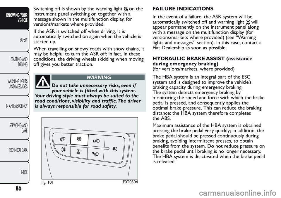
Switching off is shown by the warning lighton the
instrument panel switching on together with a
message shown in the multifunction display, for
versions/markets where provided.
If the ASR is switched off when driving, it is
automatically switched on again when the vehicle is
started up.
When travelling on snowy roads with snow chains, it
may be helpful to turn the ASR off: in fact, in these
conditions, the driving wheels skidding when moving
off gives you better traction.
WARNING
Do not take unnecessary risks, even if
your vehicle is fitted with this system.
Your driving style must always be suited to the
road conditions, visibility and traffic .The driver
is always responsible for road safety.FAILURE INDICATIONS
In the event of a failure, the ASR system will be
automatically switched off and warning light
will
appear permanently on the instrument panel along
with a message on the multifunction display (for
versions/markets where provided) (see “Warning
lights and messages” section). In this case, contact a
Fiat Dealership as soon as possible.
HYDRAULIC BRAKE ASSIST (assistance
during emergency braking)
(for versions/markets, where provided)
The HBA system is an integral part of the ESC
system and is designed to improve the vehicle’s
braking capacity during emergency braking.
The system detects emergency braking by
monitoring the speed and force with which the brake
pedal is pressed, and consequently applies the
optimal brake pressure. This can reduce the braking
distance: the HBA system therefore completes
the ABS.
Maximum assistance of the HBA system is obtained
pressing the brake pedal very quickly; in addition, the
brake pedal should be pressed continuously during
braking, avoiding intermittent presses, to obtain
benefits from the system. Do not reduce pressure on
the brake pedal until braking is no longer necessary.
The HBA system is deactivated when the brake pedal
is released.
fig. 101F0T0504
86
KNOWING YOUR
VEHICLE
SAFETY
STARTING AND
DRIVING
WARNING LIGHTS
AND MESSAGES
IN AN EMERGENCY
SERVICING AND
CARE
TECHNICAL DATA
INDEX