wheel FIAT FIORINO 2017 Owner handbook (in English)
[x] Cancel search | Manufacturer: FIAT, Model Year: 2017, Model line: FIORINO, Model: FIAT FIORINO 2017Pages: 272, PDF Size: 5.87 MB
Page 19 of 272
IGNITION SWITCH
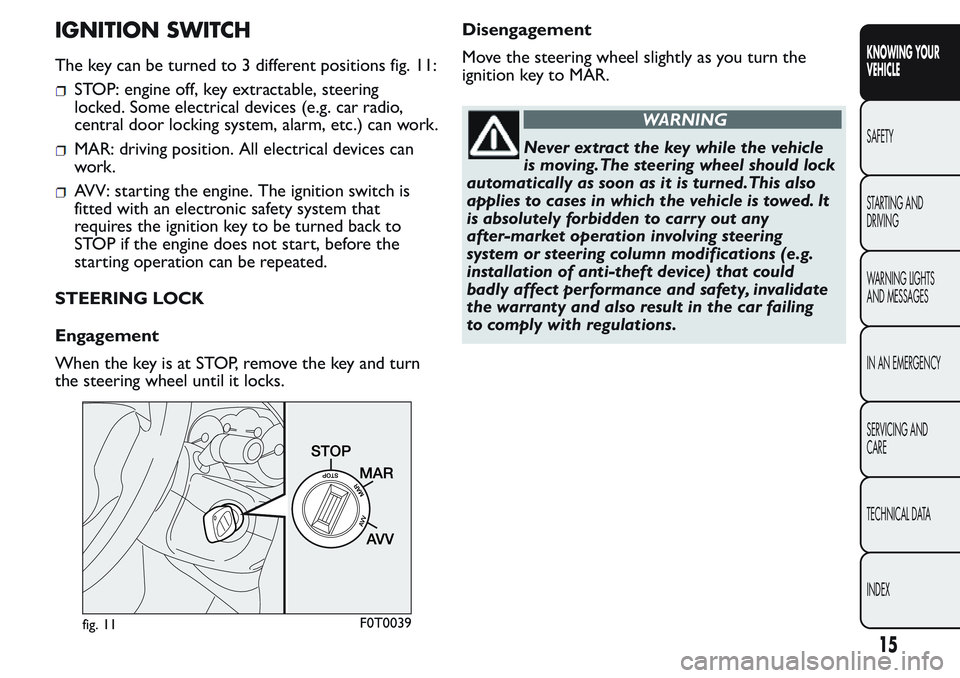
The key can be turned to 3 different positions fig. 11:
STOP: engine off, key extractable, steering
locked. Some electrical devices (e.g. car radio,
central door locking system, alarm, etc.) can work.
MAR: driving position. All electrical devices can
work.
AVV: starting the engine. The ignition switch is
fitted with an electronic safety system that
requires the ignition key to be turned back to
STOP if the engine does not start, before the
starting operation can be repeated.
STEERING LOCK
Engagement
When the key is at STOP, remove the key and turn
the steering wheel until it locks.Disengagement
Move the steering wheel slightly as you turn the
ignition key to MAR.
WARNING
Never extract the key while the vehicle
is moving.The steering wheel should lock
automatically as soon as it is turned.This also
applies to cases in which the vehicle is towed. It
is absolutely forbidden to carr y out any
after-market operation involving steering
system or steering column modifications (e.g.
installation of anti-theft device) that could
badly affect performance and safety, invalidate
the warranty and also result in the car failing
to comply with regulations.
fig. 11F0T0039
15
KNOWING YOUR
VEHICLE
SAFETY
STARTING AND
DRIVING
WARNING LIGHTS
AND MESSAGES
IN AN EMERGENCY
SERVICING AND
CARE
TECHNICAL DATA
INDEX
Page 40 of 272
SEATS
FRONT SEATS
WARNING
All adjustments must be made with the
vehicle stationary.
Lengthwise adjustment
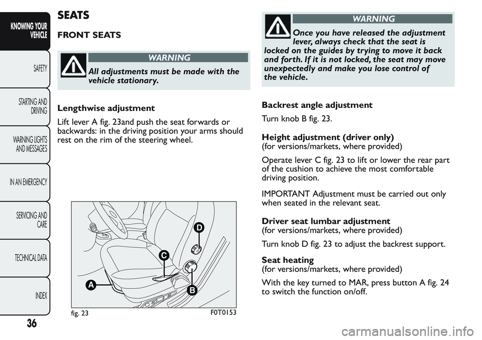
Lift lever A fig. 23and push the seat forwards or
backwards: in the driving position your arms should
rest on the rim of the steering wheel.
WARNING
Once you have released the adjustment
lever, always check that the seat is
locked on the guides by trying to move it back
and forth. If it is not locked, the seat may move
unexpectedly and make you lose control of
the vehicle.
Backrest angle adjustment
Turn knob B fig. 23.
Height adjustment (driver only)
(for versions/markets, where provided)
Operate lever C fig. 23 to lift or lower the rear part
of the cushion to achieve the most comfortable
driving position.
IMPORTANT Adjustment must be carried out only
when seated in the relevant seat.
Driver seat lumbar adjustment
(for versions/markets, where provided)
Turn knob D fig. 23 to adjust the backrest support.
Seat heating
(for versions/markets, where provided)
With the key turned to MAR, press button A fig. 24
to switch the function on/off.
B
D
C
A
fig. 23F0T0153
36
KNOWING YOUR
VEHICLE
SAFETY
STARTING AND
DRIVING
WARNING LIGHTS
AND MESSAGES
IN AN EMERGENCY
SERVICING AND
CARE
TECHNICAL DATA
INDEX
Page 47 of 272
STEERING WHEEL
The height and axial position of the steering wheel
can be adjusted on some versions.
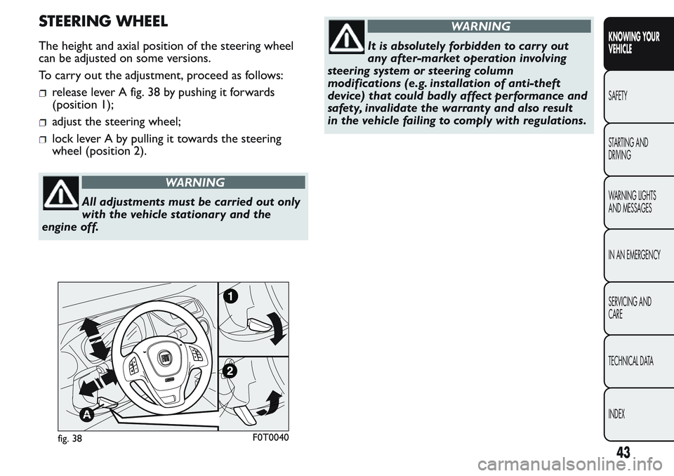
To carry out the adjustment, proceed as follows:
release lever A fig. 38 by pushing it forwards
(position 1);
adjust the steering wheel;
lock lever A by pulling it towards the steering
wheel (position 2).
WARNING
All adjustments must be carried out only
with the vehicle stationary and the
engine off.
WARNING
It is absolutely forbidden to carr y out
any after-market operation involving
steering system or steering column
modifications (e.g. installation of anti-theft
device) that could badly affect performance and
safety, invalidate the warranty and also result
in the vehicle failing to comply with regulations.
fig. 38F0T0040
43
KNOWING YOUR
VEHICLE
SAFETY
STARTING AND
DRIVING
WARNING LIGHTS
AND MESSAGES
IN AN EMERGENCY
SERVICING AND
CARE
TECHNICAL DATA
INDEX
Page 57 of 272
EXTERIOR LIGHTS
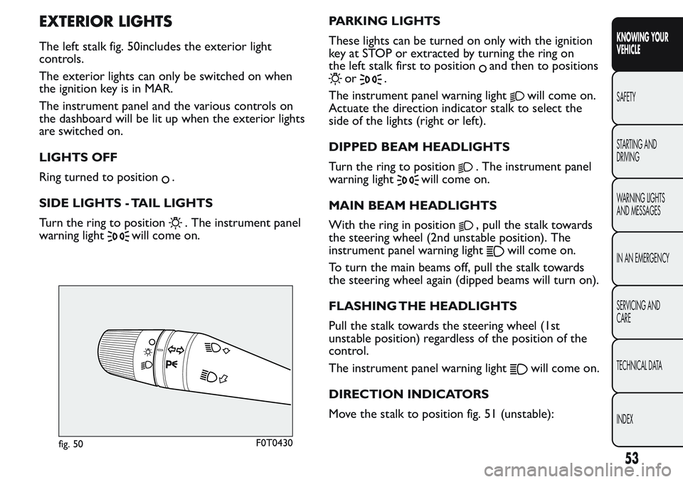
The left stalk fig. 50includes the exterior light
controls.
The exterior lights can only be switched on when
the ignition key is in MAR.
The instrument panel and the various controls on
the dashboard will be lit up when the exterior lights
are switched on.
LIGHTS OFF
Ring turned to position
.
SIDE LIGHTS - TAIL LIGHTS
Turn the ring to position
. The instrument panel
warning light
will come on.PARKING LIGHTS
These lights can be turned on only with the ignition
key at STOP or extracted by turning the ring on
the left stalk first to position
and then to positions
or.
The instrument panel warning light
will come on.
Actuate the direction indicator stalk to select the
side of the lights (right or left).
DIPPED BEAM HEADLIGHTS
Turn the ring to position
. The instrument panel
warning light
will come on.
MAIN BEAM HEADLIGHTS
With the ring in position
, pull the stalk towards
the steering wheel (2nd unstable position). The
instrument panel warning light
will come on.
To turn the main beams off, pull the stalk towards
the steering wheel again (dipped beams will turn on).
FLASHING THE HEADLIGHTS
Pull the stalk towards the steering wheel (1st
unstable position) regardless of the position of the
control.
The instrument panel warning light
will come on.
DIRECTION INDICATORS
Move the stalk to position fig. 51 (unstable):
fig. 50F0T0430
53
KNOWING YOUR
VEHICLE
SAFETY
STARTING AND
DRIVING
WARNING LIGHTS
AND MESSAGES
IN AN EMERGENCY
SERVICING AND
CARE
TECHNICAL DATA
INDEX
Page 58 of 272
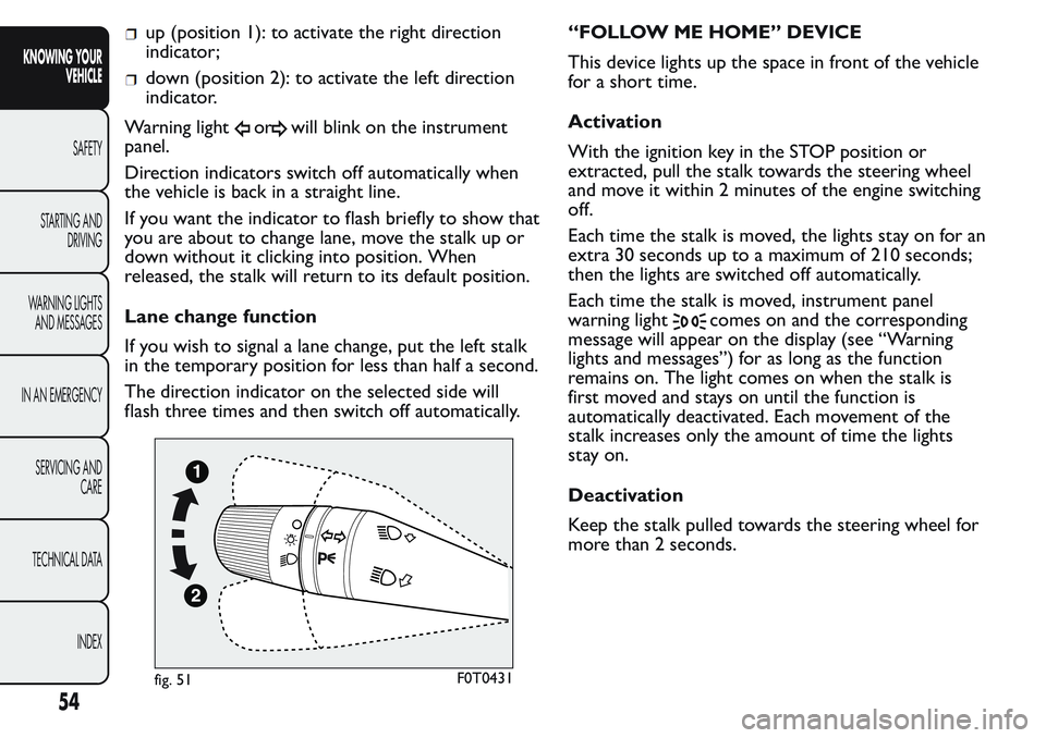
up (position 1): to activate the right direction
indicator;
down (position 2): to activate the left direction
indicator.
Warning light
orwill blink on the instrument
panel.
Direction indicators switch off automatically when
the vehicle is back in a straight line.
If you want the indicator to flash briefly to show that
you are about to change lane, move the stalk up or
down without it clicking into position. When
released, the stalk will return to its default position.
Lane change function
If you wish to signal a lane change, put the left stalk
in the temporary position for less than half a second.
The direction indicator on the selected side will
flash three times and then switch off automatically.“FOLLOW ME HOME” DEVICE
This device lights up the space in front of the vehicle
for a short time.
Activation
With the ignition key in the STOP position or
extracted, pull the stalk towards the steering wheel
and move it within 2 minutes of the engine switching
off.
Each time the stalk is moved, the lights stay on for an
extra 30 seconds up to a maximum of 210 seconds;
then the lights are switched off automatically.
Each time the stalk is moved, instrument panel
warning light
comes on and the corresponding
message will appear on the display (see “Warning
lights and messages”) for as long as the function
remains on. The light comes on when the stalk is
first moved and stays on until the function is
automatically deactivated. Each movement of the
stalk increases only the amount of time the lights
stay on.
Deactivation
Keep the stalk pulled towards the steering wheel for
more than 2 seconds.
fig. 51F0T0431
54
KNOWING YOUR
VEHICLE
SAFETY
STARTING AND
DRIVING
WARNING LIGHTS
AND MESSAGES
IN AN EMERGENCY
SERVICING AND
CARE
TECHNICAL DATA
INDEX
Page 59 of 272
WINDOW CLEANING
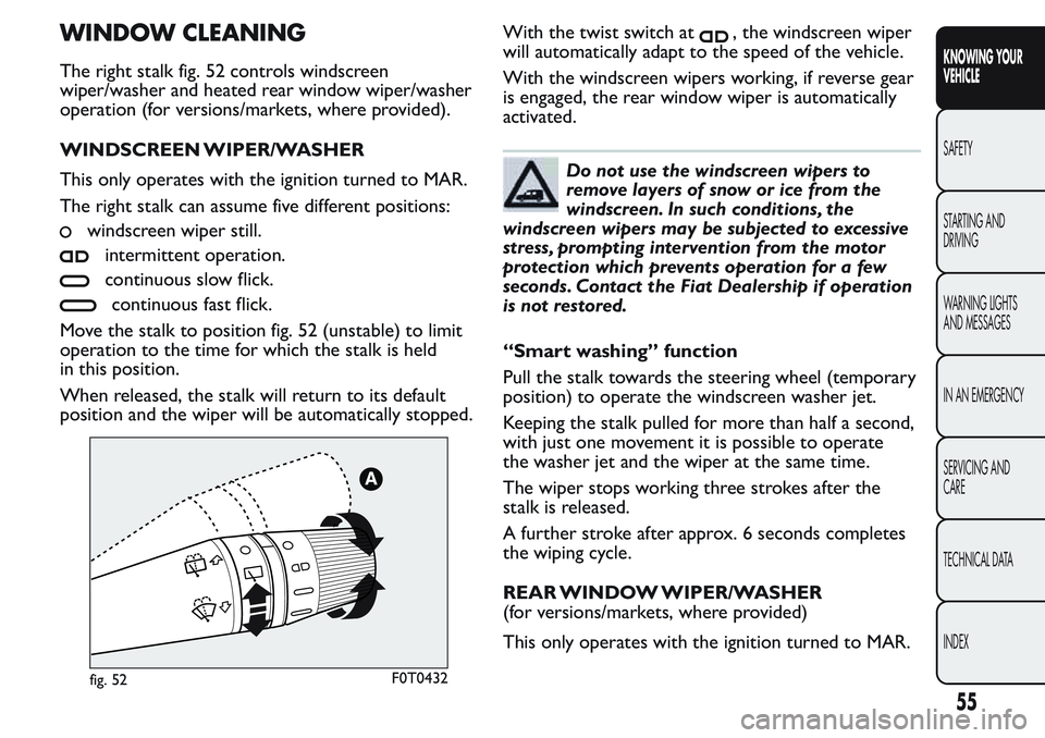
The right stalk fig. 52 controls windscreen
wiper/washer and heated rear window wiper/washer
operation (for versions/markets, where provided).
WINDSCREEN WIPER/WASHER
This only operates with the ignition turned to MAR.
The right stalk can assume five different positions:
windscreen wiper still.
intermittent operation.
continuous slow flick.
continuous fast flick.
Move the stalk to position fig. 52 (unstable) to limit
operation to the time for which the stalk is held
in this position.
When released, the stalk will return to its default
position and the wiper will be automatically stopped.With the twist switch at
, the windscreen wiper
will automatically adapt to the speed of the vehicle.
With the windscreen wipers working, if reverse gear
is engaged, the rear window wiper is automatically
activated.
Do not use the windscreen wipers to
remove layers of snow or ice from the
windscreen. In such conditions, the
windscreen wipers may be subjected to excessive
stress, prompting intervention from the motor
protection which prevents operation for a few
seconds. Contact the Fiat Dealership if operation
is not restored.
“Smart washing” function
Pull the stalk towards the steering wheel (temporary
position) to operate the windscreen washer jet.
Keeping the stalk pulled for more than half a second,
with just one movement it is possible to operate
the washer jet and the wiper at the same time.
The wiper stops working three strokes after the
stalk is released.
A further stroke after approx. 6 seconds completes
the wiping cycle.
REAR WINDOW WIPER/WASHER
(for versions/markets, where provided)
This only operates with the ignition turned to MAR.
fig. 52F0T0432
55
KNOWING YOUR
VEHICLE
SAFETY
STARTING AND
DRIVING
WARNING LIGHTS
AND MESSAGES
IN AN EMERGENCY
SERVICING AND
CARE
TECHNICAL DATA
INDEX
Page 85 of 272
ABS SYSTEM
This is an integral part of the braking system, which
prevents one or more wheels from locking or
slipping regardless of the road surface conditions and
braking intensity, giving the best control during
emergency braking.
The EBD system (Electronic Braking Force
Distribution) completes the system, allowing the
brake force to be distributed between the front and
rear wheels.
IMPORTANT For maximum efficiency of the braking
system, a bedding-in period of about 500 km is
needed: during this period it is better to avoid sharp,
repeated and prolonged braking.
SYSTEM INTERVENTION
The driver can tell the ABS system has come into
action because the brake pedal pulsates slightly and
the system gets noisier: it means that the vehicle
speed should be altered to suit the type of road
surface.
MECHANICAL BRAKE ASSIST (emergency
braking assistance)
(for versions/markets, where provided)
This system, which cannot be deactivated, recognises
emergency braking conditions (according to the
brake pedal operation speed) and provides an
additional hydraulic braking pressure to support thatprovided by the driver. This allows faster and more
powerful operation of the braking system.
IMPORTANT When the Mechanical Brake Assist is
activated, noises may be heard from the system. This
is normal. In any case, while braking keep the brake
pedal firmly depressed.
WARNING
When the ABS cuts in and you feel the
brake pedal pulsating, do not remove
your foot , but keep the pedal pushed down; in
doing so you, will stop in the shortest distance
possible under the road conditions at the time.
WARNING
If the ABS cuts in, it is a sign that the
grip between tyre and the road surface
has reached the limit : you must slow down to
match the speed to the road grip available.
WARNING
The ABS gets the most from the
available grip, but it cannot improve it ;
you should therefore take every care when
driving on slippery surfaces and not take
unnecessary risks.
81
KNOWING YOUR
VEHICLE
SAFETY
STARTING AND
DRIVING
WARNING LIGHTS
AND MESSAGES
IN AN EMERGENCY
SERVICING AND
CARE
TECHNICAL DATA
INDEX
Page 86 of 272
FAILURE INDICATIONS
ABS failure
ABS failure is indicated by warning light
in the
instrument panel coming on (together with the
appropriate message on the multifunction display on
some versions) (see “Warning lights and messages”).
In this case, the braking system will work as normal,
but without the extra capacity offered by the ABS
system. Drive carefully to the nearest Fiat Dealership
to have the system checked.
EBD failure
ABS failure is indicated by warning light
andin
the instrument panel coming on (together with the
appropriate message on the multifunction display
on some versions) (see “Warning lights and
messages”).
In this case, the rear wheels may suddenly lock and
the vehicle may swerve when braking sharply. Drive
carefully to the nearest Fiat Dealership to have
the system checked.
WARNING
If only warning lightlights up in the
instrument panel (with a message in the
multifunction display on some versions), stop
the vehicle immediately and contact the nearest
Fiat Dealership. Fluid leaking from the
hydraulic system will compromise the operation
of the braking system, whether it is of the
conventional type or with ABS.
82
KNOWING YOUR
VEHICLE
SAFETY
STARTING AND
DRIVING
WARNING LIGHTS
AND MESSAGES
IN AN EMERGENCY
SERVICING AND
CARE
TECHNICAL DATA
INDEX
Page 87 of 272
ESC (Electronic Stability Control)
SYSTEM
(for versions/markets, where provided)
The ESC system improves the directional control and
stability of the vehicle in various driving conditions.
The ESC system corrects the vehicle’s understeer
and oversteer, distributing the brake force on the
appropriate wheels. The torque supplied by the
engine can also be reduced in order to maintain
control of the vehicle.
The ESC system uses the sensors in the vehicle to
determine the trajectory required by the driver
through steering and compares it with the real
trajectory of the vehicle. When the real trajectory
deviates from the desired trajectory, the ESC system
intervenes to counter the car’s understeer or
oversteer.
Oversteer: occurs when the vehicle is turning
more than it should according to the angle of
the steering wheel
Understeer: occurs when the vehicle is turning
less than it should according to the angle of the
steering wheel
The ESC system also includes the following systems:
Hill Holder
ASR
MSR
HBASYSTEM INTERVENTION
It is signalled by the blinking of the instrument panel
warning light
, to inform the driver that the car
is in critical stability and grip conditions.
Switching the system on
The ESC system is automatically activated when the
vehicle is started and cannot be deactivated.
Failure indications
In the event of a failure, the ESC system will be
automatically switched off and warning light
will
switch on constantly on the instrument panel along
with a message on the multifunction display (for
versions/markets where provided) (see chapter
"Warning lights and messages"). Contact a Fiat
Dealership as soon as possible.
WARNING
The ESC system can’t overrule the
natural laws of physics, and can’t
increase the grip available according to the
condition of the road.
WARNING
The ESC system cannot prevent
accidents, including those due to
excessive speed on corners, driving on low-grip
surfaces or aquaplaning.
83
KNOWING YOUR
VEHICLE
SAFETY
STARTING AND
DRIVING
WARNING LIGHTS
AND MESSAGES
IN AN EMERGENCY
SERVICING AND
CARE
TECHNICAL DATA
INDEX
Page 88 of 272
WARNING
The capability of the ESC system must
never be tested irresponsibly and
dangerously, in such a way as to compromise
personal safety and the safety of others.
HILL HOLDER SYSTEM
(for versions/markets, where provided)
This system is an integral part of the ESC system and
facilitates starting on slopes.
It is automatically activated in the following
conditions:
uphill: vehicle stationary on a road with a gradient
higher than 5%, engine running, brake pedal
pressed and gearbox in neutral or gear other than
reverse;
downhill: vehicle stationary on a road with a
gradient higher than 5%, engine running, brake
pedal pressed and reverse gear engaged.
When setting off, the ESC system control unit
maintains the braking pressure on the wheels until
the torque necessary for starting is reached, or
in any case for a maximum of 2 seconds, allowing
your right foot to be moved easily from the brake
pedal to the accelerator. When two seconds have
elapsed, without starting, the system is automatically
deactivated, gradually releasing the braking pressure.
During this release stage, the typical brake
disengagement noise indicating that the vehicle is
going to move imminently will be heard.Failure indications
System failure is indicated by instrument panel
warning light
with digital display and warning light
on the instrument panel with multifunction display
(for versions/markets, where provided) (see section
“Warning lights and messages”).
IMPORTANT The Hill Holder system is not a parking
brake; therefore, never leave the vehicle without
having engaged the handbrake, turned the engine off
and engaged the first gear.
WARNING
For the ESC and ASR systems to function
correctly, all four tyres must be the
same brand and type, must be in excellent
condition and, above all, must be of the
prescribed type and size.
ASR SYSTEM (Anti-Slip Regulation)
(for versions/markets, where provided)
This is a traction control system that cuts in
automatically every time one or both drive wheels
slip.
Depending on how slippery the road is, two different
control systems are activated:
if slipping involves both driving wheels, the ASR
function intervenes reducing the power
transmitted by the engine;
84
KNOWING YOUR
VEHICLE
SAFETY
STARTING AND
DRIVING
WARNING LIGHTS
AND MESSAGES
IN AN EMERGENCY
SERVICING AND
CARE
TECHNICAL DATA
INDEX