technical specifications FIAT IDEA 2010 1.G User Guide
[x] Cancel search | Manufacturer: FIAT, Model Year: 2010, Model line: IDEA, Model: FIAT IDEA 2010 1.GPages: 210, PDF Size: 4.4 MB
Page 15 of 210
14
SAFETY
STARTING
AND DRIVING
WARNING
LIGHTS AND
MESSAGES
IN AN
EMERGENCY
MAINTENANCE
AND CARE
TECHNICAL
SPECIFICATIONS
ALPHABETICAL
INDEX
DASHBOARD
AND CONTROLS
Request for additional remote
controls
The system acknowledges up to 8 remote
controls. Should a new remote control be
necessary, contact a Fiat Dealership, tak-
ing with you the CODE card, a personal
identity document and the car’s owner-
ship documents.
Used batteries are harmful to
the environment. They should
be disposed of as specified by
law in the special containers
provided, or take them to the Fiat
Dealership, which will deal with their
disposal.
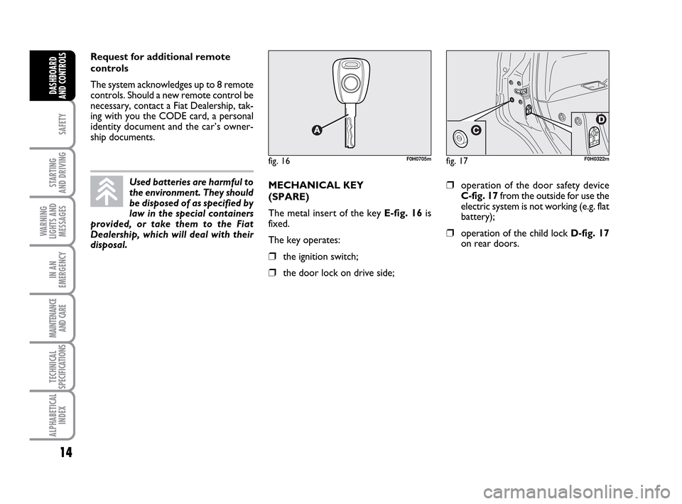
fig. 16F0H0705mfig. 17F0H0322m
MECHANICAL KEY
(SPARE)
The metal insert of the key E-fig. 16is
fixed.
The key operates:
❒the ignition switch;
❒the door lock on drive side;
❒operation of the door safety device
C-fig. 17from the outside for use the
electric system is not working (e.g. flat
battery);
❒operation of the child lock D-fig. 17
on rear doors.
001-035 LUM IDEA GB 2 ed.qxd 19-01-2010 9:14 Pagina 14
Page 16 of 210
15
SAFETY
STARTING
AND DRIVING
WARNING
LIGHTS AND
MESSAGES
IN AN
EMERGENCY
MAINTENANCE
AND CARE
TECHNICAL
SPECIFICATIONS
ALPHABETICAL
INDEX
DASHBOARD
AND CONTROLS
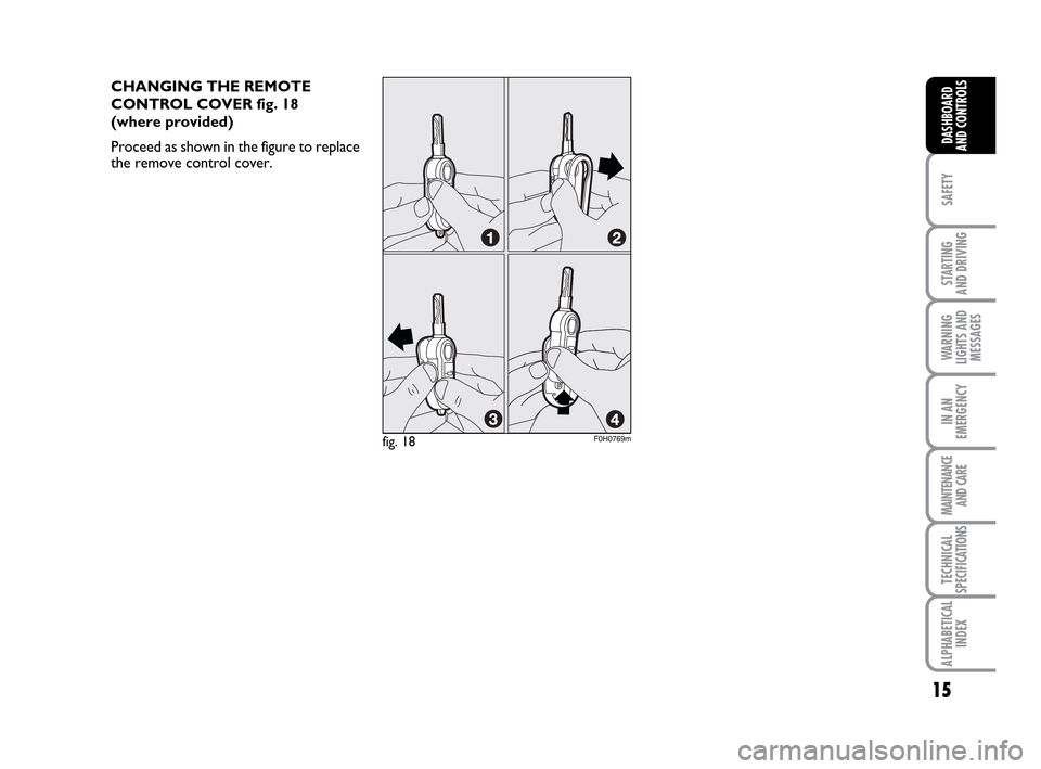
CHANGING THE REMOTE
CONTROL COVER fig. 18
(where provided)
Proceed as shown in the figure to replace
the remove control cover.
fig. 18F0H0769m
001-035 LUM IDEA GB 2 ed.qxd 19-01-2010 9:14 Pagina 15
Page 17 of 210
16
SAFETY
STARTING
AND DRIVING
WARNING
LIGHTS AND
MESSAGES
IN AN
EMERGENCY
MAINTENANCE
AND CARE
TECHNICAL
SPECIFICATIONS
ALPHABETICAL
INDEX
DASHBOARD
AND CONTROLS
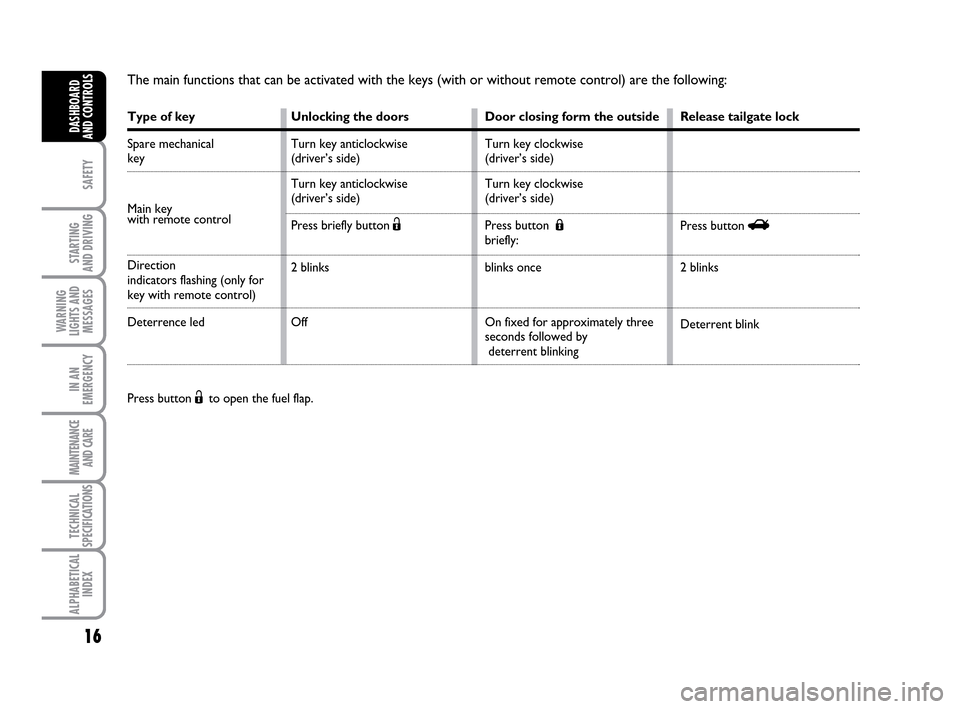
The main functions that can be activated with the keys (with or without remote control) are the following:
Press button Ëto open the fuel flap.
Type of key
Spare mechanical
key
Main key
with remote control
Direction
indicators flashing (only for
key with remote control)
Deterrence led
Release tailgate lock
Press button R
2 blinks
Deterrent blink Unlocking the doors
Turn key anticlockwise
(driver’s side)
Turn key anticlockwise
(driver’s side)
Press briefly button Ë
2 blinks
OffDoor closing form the outside
Turn key clockwise
(driver’s side)
Turn key clockwise
(driver’s side)
Press button Á
briefly:
blinks once
On fixed for approximately three
seconds followed by
deterrent blinking
001-035 LUM IDEA GB 2 ed.qxd 19-01-2010 9:14 Pagina 16
Page 18 of 210
17
SAFETY
STARTING
AND DRIVING
WARNING
LIGHTS AND
MESSAGES
IN AN
EMERGENCY
MAINTENANCE
AND CARE
TECHNICAL
SPECIFICATIONS
ALPHABETICAL
INDEX
DASHBOARD
AND CONTROLS
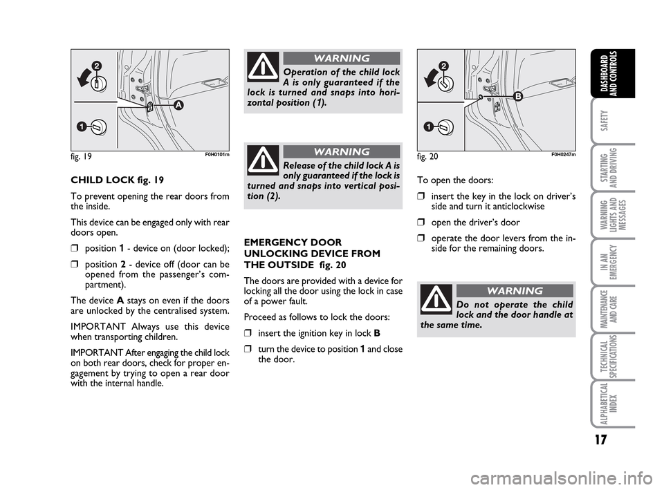
CHILD LOCK fig. 19
To prevent opening the rear doors from
the inside.
This device can be engaged only with rear
doors open.
❒position 1- device on (door locked);
❒position 2- device off (door can be
opened from the passenger’s com-
partment).
The device Astays on even if the doors
are unlocked by the centralised system.
IMPORTANT Always use this device
when transporting children.
IMPORTANT After engaging the child lock
on both rear doors, check for proper en-
gagement by trying to open a rear door
with the internal handle.
Operation of the child lock
A is only guaranteed if the
lock is turned and snaps into hori-
zontal position (
1).
WARNING
Release of the child lock A is
only guaranteed if the lock is
turned and snaps into vertical posi-
tion (2).
WARNINGfig. 19F0H0101m
EMERGENCY DOOR
UNLOCKING DEVICE FROM
THE OUTSIDE fig. 20
The doors are provided with a device for
locking all the door using the lock in case
of a power fault.
Proceed as follows to lock the doors:
❒insert the ignition key in lock B
❒turn the device to position 1and close
the door.To open the doors:
❒insert the key in the lock on driver’s
side and turn it anticlockwise
❒open the driver’s door
❒operate the door levers from the in-
side for the remaining doors.
fig. 20F0H0247m
Do not operate the child
lock and the door handle at
the same time.
WARNING
001-035 LUM IDEA GB 2 ed.qxd 19-01-2010 9:14 Pagina 17
Page 19 of 210
18
SAFETY
STARTING
AND DRIVING
WARNING
LIGHTS AND
MESSAGES
IN AN
EMERGENCY
MAINTENANCE
AND CARE
TECHNICAL
SPECIFICATIONS
ALPHABETICAL
INDEX
DASHBOARD
AND CONTROLS
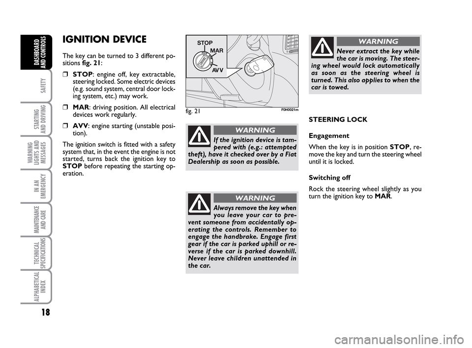
IGNITION DEVICE
The key can be turned to 3 different po-
sitions fig. 21:
❒STOP: engine off, key extractable,
steering locked. Some electric devices
(e.g. sound system, central door lock-
ing system, etc.) may work.
❒MAR: driving position. All electrical
devices work regularly.
❒AVV: engine starting (unstable posi-
tion).
The ignition switch is fitted with a safety
system that, in the event the engine is not
started, turns back the ignition key to
STOPbefore repeating the starting op-
eration.
fig. 21F0H0021m
STEERING LOCK
Engagement
When the key is in position STOP, re-
move the key and turn the steering wheel
until it is locked.
Switching off
Rock the steering wheel slightly as you
turn the ignition key to MAR.
If the ignition device is tam-
pered with (e.g.: attempted
theft), have it checked over by a Fiat
Dealership as soon as possible.
WARNING
Never extract the key while
the car is moving. The steer-
ing wheel would lock automatically
as soon as the steering wheel is
turned. This also applies to when the
car is towed.
WARNING
Always remove the key when
you leave your car to pre-
vent someone from accidentally op-
erating the controls. Remember to
engage the handbrake. Engage first
gear if the car is parked uphill or re-
verse if the car is parked downhill.
Never leave children unattended in
the car.
WARNING
001-035 LUM IDEA GB 2 ed.qxd 19-01-2010 9:14 Pagina 18
Page 20 of 210
19
SAFETY
STARTING
AND DRIVING
WARNING
LIGHTS AND
MESSAGES
IN AN
EMERGENCY
MAINTENANCE
AND CARE
TECHNICAL
SPECIFICATIONS
ALPHABETICAL
INDEX
DASHBOARD
AND CONTROLS
INSTRUMENTS
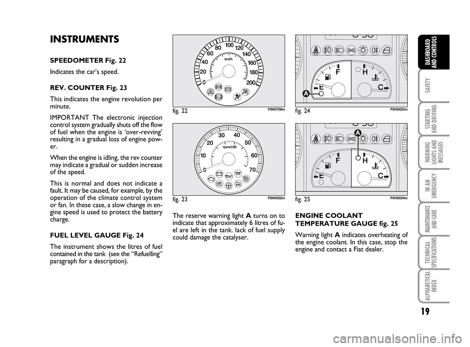
SPEEDOMETER Fig. 22
Indicates the car’s speed.
REV. COUNTER Fig. 23
This indicates the engine revolution per
minute.
IMPORTANT The electronic injection
control system gradually shuts off the flow
of fuel when the engine is ‘over-revving’
resulting in a gradual loss of engine pow-
er.
When the engine is idling, the rev counter
may indicate a gradual or sudden increase
of the speed.
This is normal and does not indicate a
fault. It may be caused, for example, by the
operation of the climate control system
or fan. In these case, a slow change in en-
gine speed is used to protect the battery
charge.
FUEL LEVEL GAUGE Fig. 24
The instrument shows the litres of fuel
contained in the tank (see the “Refuelling”
paragraph for a description).
fig. 22F0H0708m
fig. 23F0H0022m
fig. 24F0H0023m
fig. 25F0H0024m
The reserve warning light Aturns on to
indicate that approximately 6 litres of fu-
el are left in the tank. lack of fuel supply
could damage the catalyser.ENGINE COOLANT
TEMPERATURE GAUGE fig. 25
Warning light Aindicates overheating of
the engine coolant. In this case, stop the
engine and contact a Fiat dealer.
001-035 LUM IDEA GB 2 ed.qxd 19-01-2010 9:14 Pagina 19
Page 21 of 210
20
SAFETY
STARTING
AND DRIVING
WARNING
LIGHTS AND
MESSAGES
IN AN
EMERGENCY
MAINTENANCE
AND CARE
TECHNICAL
SPECIFICATIONS
ALPHABETICAL
INDEX
DASHBOARD
AND CONTROLS
This shows the temperature of the engine
coolant fluid and starts working when the
fluid temperature exceeds approx. 50°C
circa. In normal conditions, the needle may
point to different positions according to
use and the engine cooling system man-
agement.
IMPORTANT The needle will point to the
lowest value of the scale (low tempera-
ture) and warning light Awill light up to
indicate a fault in the system. Go to a Fi-
at Dealership to have the system checked.
If the needle reaches the red
area, stop the engine imme-
diately and contact a Fiat
Dealership.MULTIFUNCTIONAL
DISPLAY
(on two-line
modal panel)
The car can be equipped with the multi-
function display for showing useful infor-
mation necessary when driving according
to settings.
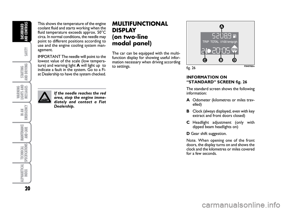
fig. 26F0H0782m
INFORMATION ON
“STANDARD” SCREEN fig. 26
The standard screen shows the following
information:
AOdometer (kilometres or miles trav-
elled)
BClock (always displayed, even with key
extract and front doors closed)
CHeadlight adjustment (only with
dipped beam headlights on)
DGear shift suggestion.
Note. When opening one of the front
doors, the display turns on and shows the
clock and the kilometres or miles covered
for a few seconds.
001-035 LUM IDEA GB 2 ed.qxd 19-01-2010 9:14 Pagina 20
Page 22 of 210
21
SAFETY
STARTING
AND DRIVING
WARNING
LIGHTS AND
MESSAGES
IN AN
EMERGENCY
MAINTENANCE
AND CARE
TECHNICAL
SPECIFICATIONS
ALPHABETICAL
INDEX
DASHBOARD
AND CONTROLS
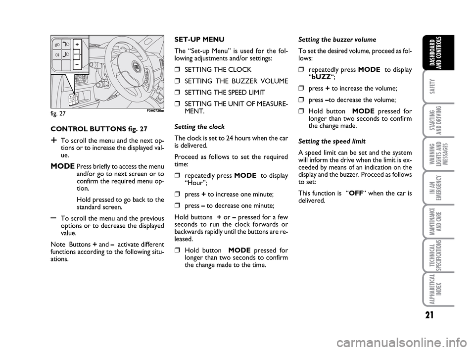
CONTROL BUTTONS fig. 27
+To scroll the menu and the next op-
tions or to increase the displayed val-
ue.
MODEPress briefly to access the menu
and/or go to next screen or to
confirm the required menu op-
tion.
Hold pressed to go back to the
standard screen.
–To scroll the menu and the previous
options or to decrease the displayed
value.
Note Buttons +and –activate different
functions according to the following situ-
ations.Setting the buzzer volume
To set the desired volume, proceed as fol-
lows:
❒repeatedly press MODE to display
“bUZZ“;
❒press +to increase the volume;
❒press –to decrease the volume;
❒Hold button MODEpressed for
longer than two seconds to confirm
the change made.
Setting the speed limit
A speed limit can be set and the system
will inform the drive when the limit is ex-
ceeded by means of an indication on the
display and the buzzer. Proceed as follows
to set:
This function is “OFF“ when the car is
delivered. SET-UP MENU
The “Set-up Menu” is used for the fol-
lowing adjustments and/or settings:
❒SETTING THE CLOCK
❒SETTING THE BUZZER VOLUME
❒SETTING THE SPEED LIMIT
❒SETTING THE UNIT OF MEASURE-
MENT.
Setting the clock
The clock is set to 24 hours when the car
is delivered.
Proceed as follows to set the required
time:
❒repeatedly press MODE to display
“Hour”;
❒press +to increase one minute;
❒press –to decrease one minute;
Hold buttons +or –pressed for a few
seconds to run the clock forwards or
backwards rapidly until the buttons are re-
leased.
❒Hold button MODEpressed for
longer than two seconds to confirm
the change made to the time.
fig. 27F0H0736m
001-035 LUM IDEA GB 2 ed.qxd 19-01-2010 9:14 Pagina 21
Page 23 of 210
22
SAFETY
STARTING
AND DRIVING
WARNING
LIGHTS AND
MESSAGES
IN AN
EMERGENCY
MAINTENANCE
AND CARE
TECHNICAL
SPECIFICATIONS
ALPHABETICAL
INDEX
DASHBOARD
AND CONTROLS
Setting the unit of measurement
Proceed as follows to set the required unit
of measurement (kilometres or miles):
❒repeatedly press MODE to dis-
play“Unit”;
❒press button + or – to change the unit
of measurement;
❒to confirm the setting, hold button
MODEpressed for longer than two
seconds.
Fuel inertia
switch tripped indication
The indication appears automatically if the
fuel inertia switch trips follow a collision
of considerable severity.
The switch cuts off fuel feed.
See the “Fuel inertia switch” chapter for
more information. Proceed as follows to select:
❒repeatedly press MODE to display
“SPEEd“;
❒press + to increase the value corre-
sponding to speed (the maximum lim-
it is 250 km/h);
❒press – to decrease the value corre-
sponding to speed (the limit is 30
km/h under which it switches to
“OFF”);
❒to confirm the setting, hold button
MODEpressed for longer than two
seconds.
If after the “FPSon” message
appears, you smell fuel or
see leaks from the fuel system, do not
reset the switch to avoid fine risk.
WARNING
001-035 LUM IDEA GB 2 ed.qxd 19-01-2010 9:14 Pagina 22
Page 24 of 210
23
SAFETY
STARTING
AND DRIVING
WARNING
LIGHTS AND
MESSAGES
IN AN
EMERGENCY
MAINTENANCE
AND CARE
TECHNICAL
SPECIFICATIONS
ALPHABETICAL
INDEX
DASHBOARD
AND CONTROLS
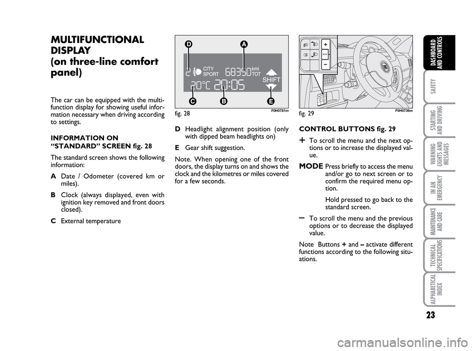
fig. 28F0H0781m
MULTIFUNCTIONAL
DISPLAY
(on three-line comfort
panel)
The car can be equipped with the multi-
function display for showing useful infor-
mation necessary when driving according
to settings.
INFORMATION ON
“STANDARD” SCREEN fig. 28
The standard screen shows the following
information:
ADate / Odometer (covered km or
miles).
BClock (always displayed, even with
ignition key removed and front doors
closed).
CExternal temperature CONTROL BUTTONS fig. 29
+To scroll the menu and the next op-
tions or to increase the displayed val-
ue.
MODEPress briefly to access the menu
and/or go to next screen or to
confirm the required menu op-
tion.
Hold pressed to go back to the
standard screen.
–To scroll the menu and the previous
options or to decrease the displayed
value.
Note Buttons +and –activate different
functions according to the following situ-
ations. DHeadlight alignment position (only
with dipped beam headlights on)
EGear shift suggestion.
Note. When opening one of the front
doors, the display turns on and shows the
clock and the kilometres or miles covered
for a few seconds.
fig. 29F0H0736m
001-035 LUM IDEA GB 2 ed.qxd 19-01-2010 9:14 Pagina 23