Steering FIAT PANDA 2009 169 / 2.G Owners Manual
[x] Cancel search | Manufacturer: FIAT, Model Year: 2009, Model line: PANDA, Model: FIAT PANDA 2009 169 / 2.GPages: 226, PDF Size: 5.29 MB
Page 4 of 226
3KNOW YOUR
VEHICLESAFETY
CORRECT USE
OF THE CAR
WARNING LIGHTS
AND MESSAGES
IN
AN EMERGENCY
CAR
MAINTENANCE
TECHNICAL
SPECIFICATIONS
INDEX
KNOW YOUR VEHICLE
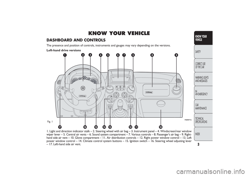
1. Light and direction indicator stalk – 2. Steering wheel with air bag – 3. Instrument panel – 4. Windscreen/rear window
wiper lever – 5. Central air vents – 6. Sound system compartment – 7. Various controls – 8. Passenger’s air bag – 9. Right-
hand side air vent – 10. Glove compartment – 11. Air distribution controls – 12. Right power window control – 13. Left
power window control – 14. Climate control system buttons – 15. Ignition switch – 16. Steering wheel adjusting lever
– 17. Left-hand side air vent.
F0Z0677m
Fig. 1DASHBOARD AND CONTROLSThe presence and position of controls, instruments and gauges may vary depending on the versions.
Left-hand drive versions
001-030 PANDA EN 7-10-2009 13:39 Pagina 3
Page 5 of 226
4
KNOW YOUR
VEHICLE
SAFETY
CORRECT USE
OF THE CAR
WARNING LIGHTS
AND MESSAGES
IN
AN EMERGENCY
CAR
MAINTENANCE
TECHNICAL
SPECIFICATIONS
INDEX
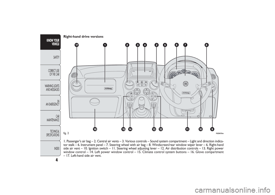
Right-hand drive versions
1. Passenger’s air bag – 2. Central air vents – 3. Various controls – Sound system compartment – Light and direction indica-
tor stalk – 6. Instrument panel – 7. Steering wheel with air bag – 8. Windscreen/rear window wiper lever – 6. Right-hand
side air vent – 10. Ignition switch – 11. Steering wheel adjusting lever – 12. Air distribution controls – 13. Right power
window control – 14. Left power window control – 15. Climate control system buttons – 16. Glove compartment
– 17. Left-hand side air vent.
CH
F
E
F0Z0678m
fig. 2
001-030 PANDA EN 7-10-2009 13:39 Pagina 4
Page 10 of 226
9KNOW YOUR
VEHICLESAFETY
CORRECT USE
OF THE CAR
WARNING LIGHTS
AND MESSAGES
IN
AN EMERGENCY
CAR
MAINTENANCE
TECHNICAL
SPECIFICATIONS
INDEX
F0Z0683m
fig. 8
F0Z0684m
fig. 9
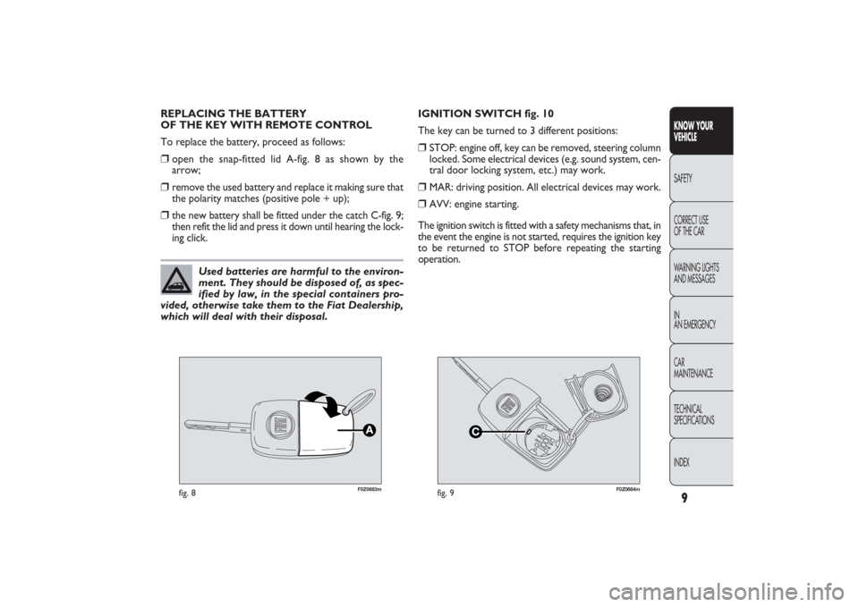
REPLACING THE BATTERY
OF THE KEY WITH REMOTE CONTROL
To replace the battery, proceed as follows:âť’
open the snap-fitted lid A-fig. 8 as shown by the
arrow;
âť’
remove the used battery and replace it making sure that
the polarity matches (positive pole + up);
âť’
the new battery shall be fitted under the catch C-fig. 9;
then refit the lid and press it down until hearing the lock-
ing click.IGNITION SWITCH fig. 10
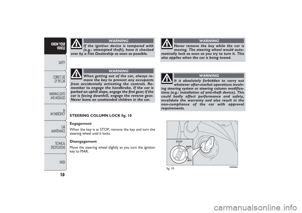
The key can be turned to 3 different positions:
âť’
STOP: engine off, key can be removed, steering column
locked. Some electrical devices (e.g. sound system, cen-
tral door locking system, etc.) may work.
âť’
MAR: driving position. All electrical devices may work.
âť’
AVV: engine starting.
The ignition switch is fitted with a safety mechanisms that, in
the event the engine is not started, requires the ignition key
to be returned to STOP before repeating the starting
operation.
Used batteries are harmful to the environ-
ment. They should be disposed of, as spec-
ified by law, in the special containers pro-
vided, otherwise take them to the Fiat Dealership,
which will deal with their disposal.
001-030 PANDA EN 7-10-2009 13:39 Pagina 9
Page 11 of 226
F0Z0026m
fig. 10
STEERING COLUMN LOCK fig. 10
Engagement
When the key is at STOP, remove the key and turn the
steering wheel until it locks.
Disengagement
Move the steering wheel slightly as you turn the ignition
key to MAR.
10
KNOW YOUR
VEHICLE
SAFETY
CORRECT USE
OF THE CAR
WARNING LIGHTS
AND MESSAGES
IN
AN EMERGENCY
CAR
MAINTENANCE
TECHNICAL
SPECIFICATIONS
INDEX
If the ignition device is tampered with
(e.g.: attempted theft), have it checked
over by a Fiat Dealership as soon as possible.
WARNING
When getting out of the car, always re-
move the key to prevent any occupants
from accidentally activating the controls. Re-
member to engage the handbrake. If the car is
parked on uphill slope, engage the first gear; if the
car is facing downhill, engage the reverse gear.
Never leave an unattended children in the car.
WARNING
Never remove the key while the car is
moving. The steering wheel would auto-
matically lock as soon as you try to turn it. This
also applies when the car is being towed.
WARNING
It is absolutely forbidden to carry out
whatever after-market operations involv-
ing steering system or steering column modifica-
tions (e.g.: installation of anti-theft device). This
could badly affect performance and safety,
invalidate the warranty and also result in the
non-compliance of the car with approval
requirements.
WARNING
001-030 PANDA EN 7-10-2009 13:39 Pagina 10
Page 18 of 226
17KNOW YOUR
VEHICLESAFETY
CORRECT USE
OF THE CAR
WARNING LIGHTS
AND MESSAGES
IN
AN EMERGENCY
CAR
MAINTENANCE
TECHNICAL
SPECIFICATIONS
INDEX
F0Z0185m
fig. 22
F0Z0016m
fig. 23
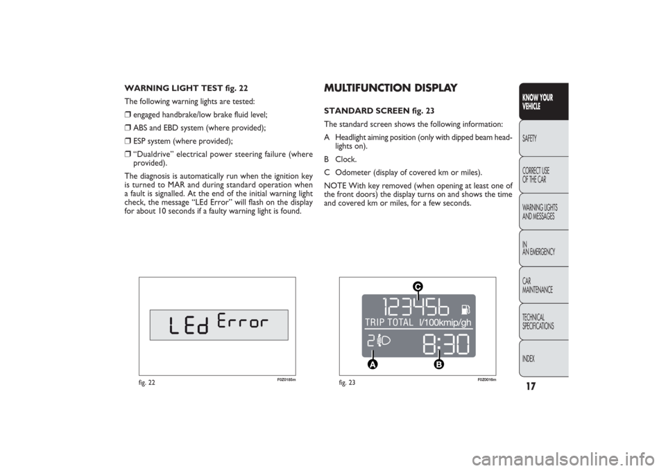
MULTIFUNCTION DISPLAY STANDARD SCREEN fig. 23
The standard screen shows the following information:
A Headlight aiming position (only with dipped beam head-
lights on).
B Clock.
C Odometer (display of covered km or miles).
NOTE With key removed (when opening at least one of
the front doors) the display turns on and shows the time
and covered km or miles, for a few seconds. WARNING LIGHT TEST fig. 22
The following warning lights are tested:
âť’
engaged handbrake/low brake fluid level;
âť’
ABS and EBD system (where provided);
âť’
ESP system (where provided);
âť’
“Dualdrive” electrical power steering failure (where
provided).
The diagnosis is automatically run when the ignition key
is turned to MAR and during standard operation when
a fault is signalled. At the end of the initial warning light
check, the message “LEd Error” will flash on the display
for about 10 seconds if a faulty warning light is found.
001-030 PANDA EN 7-10-2009 13:39 Pagina 17
Page 19 of 226
18
KNOW YOUR
VEHICLE
SAFETY
CORRECT USE
OF THE CAR
WARNING LIGHTS
AND MESSAGES
IN
AN EMERGENCY
CAR
MAINTENANCE
TECHNICAL
SPECIFICATIONS
INDEX
F0I0142m
fig. 24
F0Z0152m
fig. 25
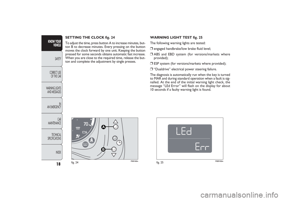
WARNING LIGHT TEST fig. 25
The following warning lights are tested:âť’
engaged handbrake/low brake fluid level;
âť’
ABS and EBD system (for versions/markets where
provided);
âť’
ESP system (for versions/markets where provided);
âť’
“Dualdrive” electrical power steering failure.
The diagnosis is automatically run when the key is turned
to MAR and during standard operation when a fault is sig-
nalled. At the end of the initial warning light check, the
message “LEd Error” will flash on the display for about
10 seconds if a faulty warning light is found. SETTING THE CLOCK fig. 24
To adjust the time, press button A to increase minutes, but-
ton B to decrease minutes. Every pressing on the button
moves the clock forward by one unit. Keeping the button
pressed for some seconds obtains automatic fast increase.
When you are close to the required time, release the but-
ton and complete the adjustment by single presses.
001-030 PANDA EN 7-10-2009 13:39 Pagina 18
Page 32 of 226
F0Z0029m
fig. 31
F0Z0030m
fig. 32
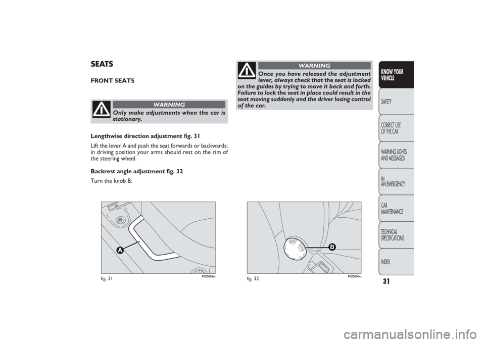
SEATSFRONT SEATS
Only make adjustments when the car is
stationary.
WARNING
Lengthwise direction adjustment fig. 31
Lift the lever A and push the seat forwards or backwards:
in driving position your arms should rest on the rim of
the steering wheel.
Backrest angle adjustment fig. 32
Turn the knob B.
Once you have released the adjustment
lever, always check that the seat is locked
on the guides by trying to move it back and forth.
Failure to lock the seat in place could result in the
seat moving suddenly and the driver losing control
of the car.
WARNING
31KNOW YOUR
VEHICLESAFETY
CORRECT USE
OF THE CAR
WARNING LIGHTS
AND MESSAGES
IN
AN EMERGENCY
CAR
MAINTENANCE
TECHNICAL
SPECIFICATIONS
INDEX
031-064 PANDA EN 7-10-2009 13:43 Pagina 31
Page 35 of 226
F0Z0034m
fig. 35
F0Z0061m
fig. 36
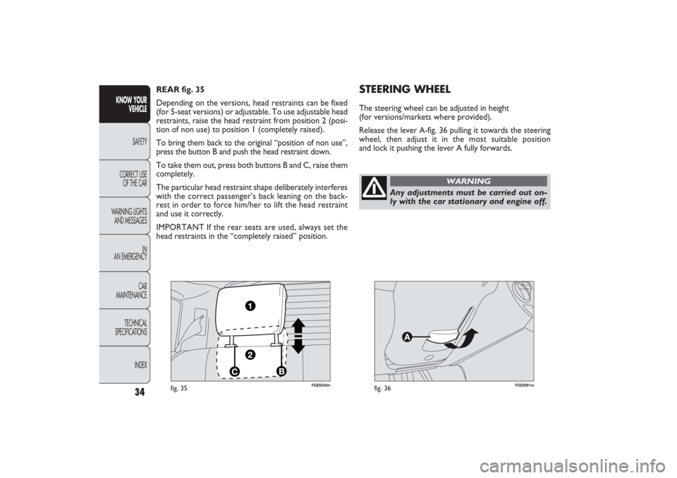
STEERING WHEELThe steering wheel can be adjusted in height
(for versions/markets where provided).
Release the lever A-fig. 36 pulling it towards the steering
wheel, then adjust it in the most suitable position
and lock it pushing the lever A fully forwards. REAR fig. 35
Depending on the versions, head restraints can be fixed
(for 5-seat versions) or adjustable. To use adjustable head
restraints, raise the head restraint from position 2 (posi-
tion of non use) to position 1 (completely raised).
To bring them back to the original “position of non use”,
press the button B and push the head restraint down.
To take them out, press both buttons B and C, raise them
completely.
The particular head restraint shape deliberately interferes
with the correct passenger’s back leaning on the back-
rest in order to force him/her to lift the head restraint
and use it correctly.
IMPORTANT If the rear seats are used, always set the
head restraints in the “completely raised” position.
34
KNOW YOUR
VEHICLE
SAFETY
CORRECT USE
OF THE CAR
WARNING LIGHTS
AND MESSAGES
IN
AN EMERGENCY
CAR
MAINTENANCE
TECHNICAL
SPECIFICATIONS
INDEX
Any adjustments must be carried out on-
ly with the car stationary and engine off.
WARNING
031-064 PANDA EN 7-10-2009 13:43 Pagina 34
Page 49 of 226
F0Z0122m
fig. 48
F0Z0126m
fig. 49
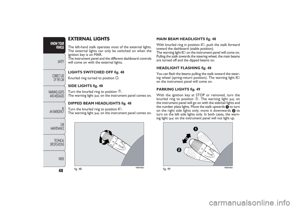
MAIN BEAM HEADLIGHTS fig. 48
With knurled ring in position
2
, push the stalk forward
toward the dashboard (stable position).
The warning light
1
on the instrument panel will come on.
Pulling the stalk towards the steering wheel, the main beams
are turned off and the dipped beams on.
HEADLIGHT FLASHING fig. 48
You can flash the beams pulling the stalk toward the steer-
ing wheel (spring-return position). The warning light
1
on the instrument panel will come on.
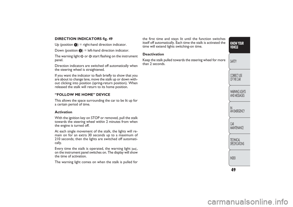
PARKING LIGHTS fig. 49
With the ignition key at STOP or removed, turn the
knurled ring to position
6
. The warning light
3
on
the instrument panel will go on with the side/tail lights and
the number plate lights. Move the stalk upwards
a
to turn
on the right side lights only; move it downwards b
to
turn on the left side lights only. In both cases, the warn-
ing light
3
on the instrument panel will not light up.
EXTERNAL LIGHTSThe left-hand stalk operates most of the external lights.
The external lights can only be switched on when the
ignition key is on MAR.
The instrument panel and the different dashboard controls
will come on with the external lights.
LIGHTS SWITCHED OFF fig. 48
Knurled ring turned to position O.
SIDE LIGHTS fig. 48
Turn the knurled ring to position
6
.
The warning light
3
on the instrument panel comes on.
DIPPED BEAM HEADLIGHTS fig. 48
Turn the knurled ring to position
2
.
The warning light
3
on the instrument panel comes on.
48
KNOW YOUR
VEHICLE
SAFETY
CORRECT USE
OF THE CAR
WARNING LIGHTS
AND MESSAGES
IN
AN EMERGENCY
CAR
MAINTENANCE
TECHNICAL
SPECIFICATIONS
INDEX
031-064 PANDA EN 7-10-2009 13:43 Pagina 48
Page 50 of 226
49KNOW YOUR
VEHICLESAFETY
CORRECT USE
OF THE CAR
WARNING LIGHTS
AND MESSAGES
IN
AN EMERGENCY
CAR
MAINTENANCE
TECHNICAL
SPECIFICATIONS
INDEX
the first time and stays lit until the function switches
itself off automatically. Each time the stalk is activated the
time will extend lights switching-on time.
Deactivation
Keep the stalk pulled towards the steering wheel for more
than 2 seconds. DIRECTION INDICATORS fig. 49
Up (position
a) = right-hand direction indicator.
Down (position b) = left-hand direction indicator.
The warning light ÂĄ
or
ĂŽ
start flashing on the instrument
panel.
Direction indicators are switched off automatically when
the steering wheel is straightened.
If you want the indicator to flash briefly to show that you
are about to change lane, move the stalk up or down with-
out clicking into position (spring-return position). When
released the stalk will return to its home position.
“FOLLOW ME HOME” DEVICE
This allows the space surrounding the car to be lit up for
a certain period of time.
Activation
With the ignition key on STOP or removed, pull the stalk
towards the steering wheel within 2 minutes from when
the engine is turned off.
At each single movement of the stalk, the lights will re-
main on for an extra 30 seconds up to a maximum of
210 seconds; then the lights are switched off automati-
cally.
Every time the stalk is operated, the warning light
3
,
on the instrument panel switches on. The display will show
the time of activation.
The warning light comes on when the stalk is pulled for
031-064 PANDA EN 7-10-2009 13:43 Pagina 49