technical specifications FIAT SCUDO 2012 Owner handbook (in English)
[x] Cancel search | Manufacturer: FIAT, Model Year: 2012, Model line: SCUDO, Model: FIAT SCUDO 2012Pages: 219, PDF Size: 4.13 MB
Page 148 of 219
144
WARNING
LIGHTS AND
MESSAGES
VEHICLE
MAINTENANCE
TECHNICAL
SPECIFICATIONS
INDEX
DASHBOARD
AND CONTROLS
SAFETY
DEVICES
CORRECT USE
OF THE
VEHICLE
IN AN
EMERGENCY
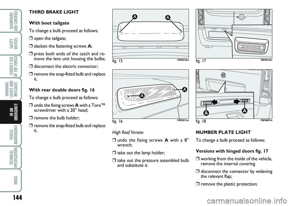
THIRD BRAKE LIGHT
With boot tailgate
To change a bulb proceed as follows:
❒open the tailgate;
❒slacken the fastening screws A;
❒press both ends of the catch and re-
move the lens unit housing the bulbs;
❒disconnect the electric connector;
❒remove the snap-fitted bulb and replace
it.
With rear double doors fig. 16
To change a bulb proceed as follows:
❒undo the fixing screws Awith a Torx™
screwdriver with a 20” head;
❒remove the bulb holder;
❒remove the snap-fitted bulb and replace
it.
NUMBER PLATE LIGHT
To change a bulb proceed as follows:
Versions with hinged doors fig. 17
❒working from the inside of the vehicle,
remove the internal covering
❒disconnect the connector by widening
the relevant flap;
❒remove the plastic protection;
fig. 15
AA
F0P0210m
fig. 16
A
A
F0P0211m
fig. 17F0P0212m
fig. 18F0P0607m
High Roof Version
❒undo the fixing screws Awith a 8”
wrench;
❒take out the lamp holder;
❒take out the pressure assembled bulb
and substitute it.
Page 149 of 219
145
WARNING
LIGHTS AND
MESSAGES
VEHICLE
MAINTENANCE
TECHNICAL
SPECIFICATIONS
INDEX
DASHBOARD
AND CONTROLS
SAFETY
DEVICES
CORRECT USE
OF THE
VEHICLE
IN AN
EMERGENCY
IF AN INTERIOR BULB
BURNS OUT
For the type of bulb and power rating, see
paragraph “When needing to change a
bulb”.
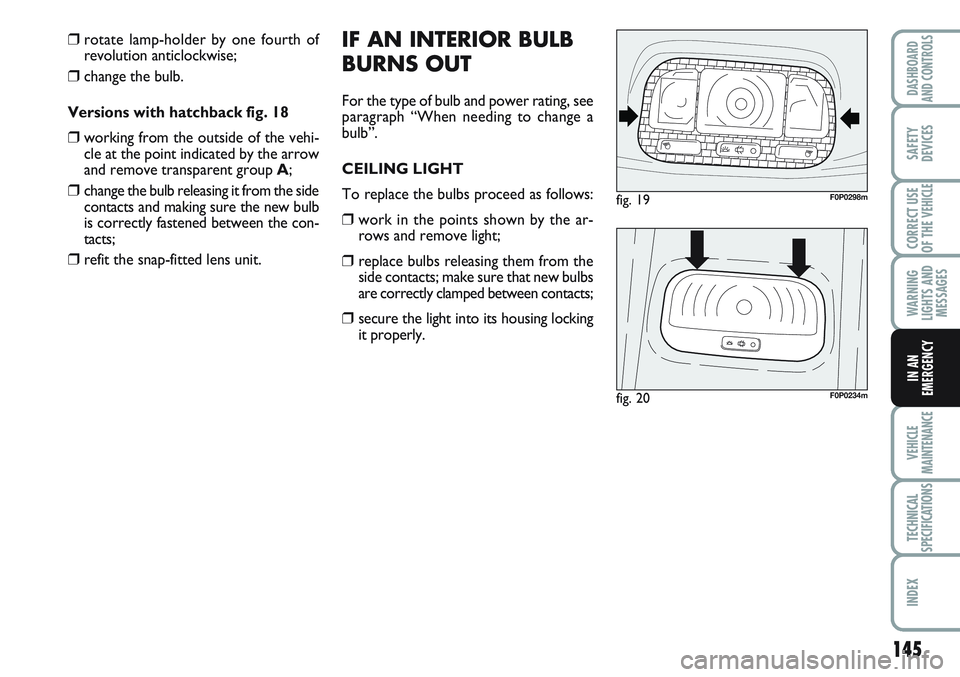
CEILING LIGHT
To replace the bulbs proceed as follows:
❒work in the points shown by the ar-
rows and remove light;
❒replace bulbs releasing them from the
side contacts; make sure that new bulbs
are correctly clamped between contacts;
❒secure the light into its housing locking
it properly.
fig. 19F0P0298m
fig. 20F0P0234m
❒rotate lamp-holder by one fourth of
revolution anticlockwise;
❒change the bulb.
Versions with hatchback fig. 18
❒working from the outside of the vehi-
cle at the point indicated by the arrow
and remove transparent group A;
❒change the bulb releasing it from the side
contacts and making sure the new bulb
is correctly fastened between the con-
tacts;
❒refit the snap-fitted lens unit.
Page 150 of 219
146
WARNING
LIGHTS AND
MESSAGES
VEHICLE
MAINTENANCE
TECHNICAL
SPECIFICATIONS
INDEX
DASHBOARD
AND CONTROLS
SAFETY
DEVICES
CORRECT USE
OF THE
VEHICLE
IN AN
EMERGENCY
IF A FUSE BLOWS
GENERAL FEATURES
The fuse is a protective device for the
electric system: it comes into action (i.e.
it cuts off) mainly due to a fault or im-
proper action on the system.
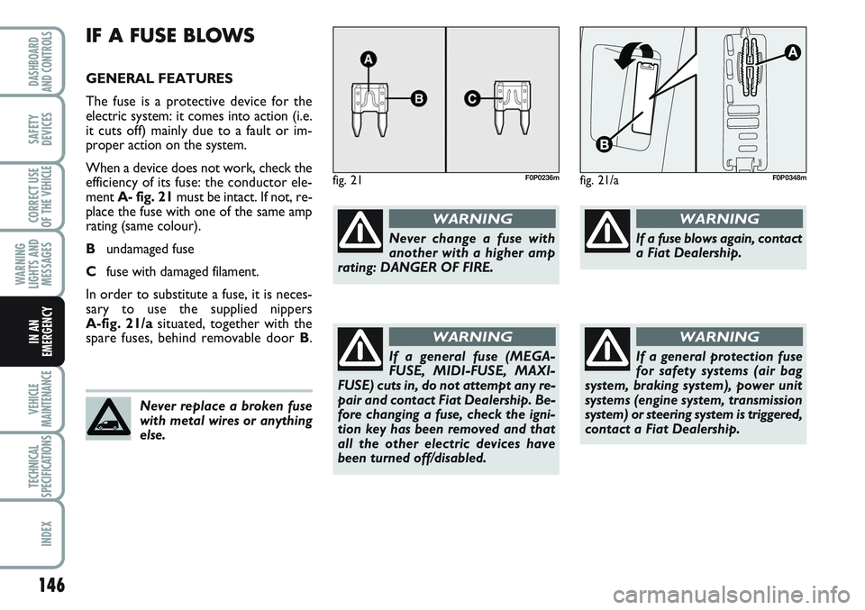
When a device does not work, check the
efficiency of its fuse: the conductor ele-
ment A- fig. 21must be intact. If not, re-
place the fuse with one of the same amp
rating (same colour).
Bundamaged fuse
Cfuse with damaged filament.
In order to substitute a fuse, it is neces-
sary to use the supplied nippers
A-fig. 21/asituated, together with the
spare fuses, behind removable door B.
fig. 21F0P0236m
Never change a fuse with
another with a higher amp
rating: DANGER OF FIRE.
WARNING
Never replace a broken fuse
with metal wires or anything
else.
If a general fuse (MEGA-
FUSE, MIDI-FUSE, MAXI-
FUSE) cuts in, do not attempt any re-
pair and contact Fiat Dealership. Be-
fore changing a fuse, check the igni-
tion key has been removed and that
all the other electric devices have
been turned off/disabled.
WARNING
If a general protection fuse
for safety systems (air bag
system, braking system), power unit
systems (engine system, transmission
system) or steering system is triggered,
contact a Fiat Dealership.
WARNING
If a fuse blows again, contact
a Fiat Dealership.
WARNING
fig. 21/aF0P0348m
Page 151 of 219
147
WARNING
LIGHTS AND
MESSAGES
VEHICLE
MAINTENANCE
TECHNICAL
SPECIFICATIONS
INDEX
DASHBOARD
AND CONTROLS
SAFETY
DEVICES
CORRECT USE
OF THE
VEHICLE
IN AN
EMERGENCY
fig. 22F0P0299m
F1
F2
F4
F5
F6
F7
F8
F9
F10
F11
F12
F13
F14
F15
F16
F1715
–
10
30
30
5
20
10
30
15
15
5
15
30
–
40
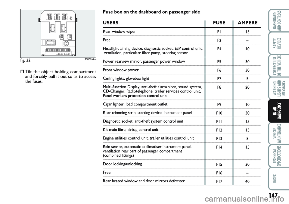
Fuse box on the dashboard on passenger side
USERS FUSE AMPERE
Rear window wiper
Free
Headlight aiming device, diagnostic socket, ESP control unit,
ventilation, particulate filter pump, steering sensor
Power rearview mirror, passenger power window
Front window power
Ceiling lights, glovebox light
Multi-function Display, anti-theft alarm siren, sound system,
CD-Changer, Radiotelephone, trailer services control unit,
Panel workers protection control unit
Cigar lighter, load compartment outlet
Rear trimming strip, starting device, instrument panel
Diagnostic socket, anti-theft system control unit
Kit main libre, airbag control unit
Engine utilities control unit, trailer utilities control unit
Rain sensor, automatic acclimatiser instrument panel,
ventilation rear part of passenger compartment
(combined fittings)
Door locking/unlocking
Free
Rear heated window and door mirrors defroster
❒Tilt the object holding compartment
and forcibly pull it out so as to access
the fuses.
Page 152 of 219
148
WARNING
LIGHTS AND
MESSAGES
VEHICLE
MAINTENANCE
TECHNICAL
SPECIFICATIONS
INDEX
DASHBOARD
AND CONTROLS
SAFETY
DEVICES
CORRECT USE
OF THE
VEHICLE
IN AN
EMERGENCY
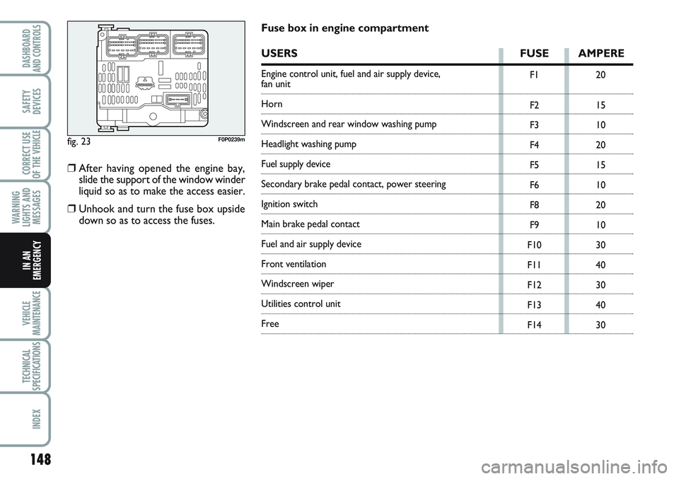
fig. 23F0P0239m
F1
F2
F3
F4
F5
F6
F8
F9
F10
F11
F12
F13
F1420
15
10
20
15
10
20
10
30
40
30
40
30
Fuse box in engine compartment
USERS FUSE AMPERE
Engine control unit, fuel and air supply device, fan unit
Horn
Windscreen and rear window washing pump
Headlight washing pump
Fuel supply device
Secondary brake pedal contact, power steering
Ignition switch
Main brake pedal contact
Fuel and air supply device
Front ventilation
Windscreen wiper
Utilities control unit
Free
❒After having opened the engine bay,
slide the support of the window winder
liquid so as to make the access easier.
❒Unhook and turn the fuse box upside
down so as to access the fuses.
Page 153 of 219
149
WARNING
LIGHTS AND
MESSAGES
VEHICLE
MAINTENANCE
TECHNICAL
SPECIFICATIONS
INDEX
DASHBOARD
AND CONTROLS
SAFETY
DEVICES
CORRECT USE
OF THE
VEHICLE
IN AN
EMERGENCY
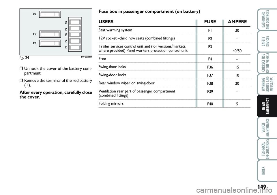
fig. 24
F1
F2
F3
F1 F4 F3 F4 F5
F0P0241m
F1
F2
F3
F4
F36
F37
F38
F39
F4030
–
40/50
–
15
10
20
–
5
Fuse box in passenger compartment (on battery)
USERS FUSE AMPERE
Seat warming system
12V socket –third row seats (combined fittings)
Trailer services control unit and (for versions/markets,
where provided) Panel workers protection control unit
Free
Swing-door locks
Swing-door locks
Rear window wiper on swing-door
Ventilation rear part of passenger compartment
(combined fittings)
Folding mirrors
❒Unhook the cover of the battery com-
partment.
❒Remove the terminal of the red battery
(+).
After every operation, carefully close
the cover.
Page 154 of 219
150
WARNING
LIGHTS AND
MESSAGES
VEHICLE
MAINTENANCE
TECHNICAL
SPECIFICATIONS
INDEX
DASHBOARD
AND CONTROLS
SAFETY
DEVICES
CORRECT USE
OF THE
VEHICLE
IN AN
EMERGENCY
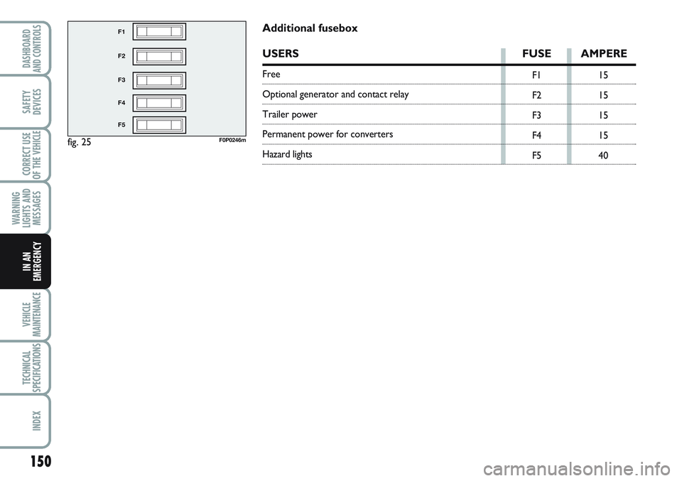
fig. 25
F1
F2
F3
F4
F5
F0P0246m
F1
F2
F3
F4
F515
15
15
15
40
Additional fusebox
USERS FUSE AMPERE
Free
Optional generator and contact relay
Trailer power
Permanent power for converters
Hazard lights
Page 155 of 219
151
WARNING
LIGHTS AND
MESSAGES
VEHICLE
MAINTENANCE
TECHNICAL
SPECIFICATIONS
INDEX
DASHBOARD
AND CONTROLS
SAFETY
DEVICES
CORRECT USE
OF THE
VEHICLE
IN AN
EMERGENCY
IF THE BATTERY IS FLAT
IMPORTANT The battery charging pro-
cedure is described only for information
purposes. This operation should be car-
ried out by Fiat Dealership.
Charging should be slow at a low amp rat-
ing for 24 hours. Charging for a longer
time may damage the battery.
Charge the battery as follows:
❒disconnect battery negative terminal;
❒connect the charger cables to the bat-
tery terminals, observing the poles;
❒turn on the charger;
❒when you have finished, turn the charg-
er off before disconnecting the battery;
❒reconnect battery negative terminal.
The liquid contained in the
battery is poisonous and cor-
rosive. Avoid contact with the skin or
eyes. The battery should be charged
in a well ventilated place, away from
naked flames or possible sources of
sparks: danger of explosion and fire.
WARNING
Do not attempt to charge a
frozen battery: it must first-
ly be thawed, otherwise it may burst.
If freezing has occurred, the battery
should be checked by skilled person-
nel to make sure that the internal el-
ements are not damaged and that the
body is not cracked, with the risk of
leaking poisonous and corrosive acid.
WARNING
ECONOMY MODE
After switching off the engine, when the
key is at the Mposition, some functions
(windscreen wipers, window winders,
map lights, car radio, etc.) can be used on-
ly for a maximum of thirty minutes, so as
to avoid the battery to be run down.
Once these thirty minutes have passed,
the active functions are put in stand-by and
the warning light of the battery flashes, ac-
companied by a message on the display.
To immediately recover the use of these
functions, it is necessary to start the en-
gine and to keep it running for a few sec-
onds.
The time which will be available will be the
double of the engine starting time.
However, this period of time will be be-
tween five and thirty minutes.
If the battery is run down, the engine can-
not be started.
Page 156 of 219
152
WARNING
LIGHTS AND
MESSAGES
VEHICLE
MAINTENANCE
TECHNICAL
SPECIFICATIONS
INDEX
DASHBOARD
AND CONTROLS
SAFETY
DEVICES
CORRECT USE
OF THE
VEHICLE
IN AN
EMERGENCY
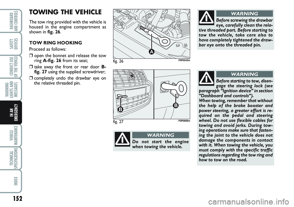
fig. 26
A
F0P0243m
Do not start the engine
when towing the vehicle.
WARNING
Before screwing the drawbar
eye, carefully clean the rela-
tive threaded part. Before starting to
tow the vehicle, take care also to
have completely tightened the draw-
bar eye onto the threaded pin.
WARNING
Before starting to tow, disen-
gage the steering lock (see
paragraph “Ignition device” in section
“Dashboard and controls”).
When towing, remember that without
the help of the brake booster and
power steering, a greater effort is re-
quired on the pedal and steering
wheel. Do not use flexible cables for
towing and avoid jerks. During tow-
ing operations make sure that fasten-
ing the joint to the vehicle does not
damage the components in contact
with it. When towing the vehicle, you
must comply with the specific traffic
regulations regarding the tow ring and
how to tow on the road.
WARNING
fig. 27F0P0608m
TOWING THE VEHICLE
The tow ring provided with the vehicle is
housed in the engine compartment as
shown in fig. 26.
TOW RING HOOKING
Proceed as follows:
❒open the bonnet and release the tow
ring A-fig. 26from its seat;
❒take away the front or rear door B-
fig. 27using the supplied screwdriver;
❒completely undo the drawbar eye on
the relative threaded pin.
Page 157 of 219
153
WARNING
LIGHTS AND
MESSAGES
TECHNICAL
SPECIFICATIONS
INDEX
DASHBOARD
AND CONTROLS
SAFETY
DEVICES
CORRECT USE
OF THE
VEHICLE
IN AN
EMERGENCY
VEHICLE
MAINTENANCE
SCHEDULED SERVICING ................................................. 154
SERVICE SCHEDULE .......................................................... 155
ROUTINE MAINTENANCE ............................................. 157
HEAVY-DUTY....................................................................... 157
CHECKING FLUID LEVELS .............................................. 158
AIR CLEANER / POLLEN FILTER..................................... 164
BATTERY ............................................................................... 164
WHEELS AND TYRES ........................................................ 167
RUBBER HOSES ................................................................... 168
WINDSCREEN/REAR WINDOW WIPERS .................. 168
BODYWORK ....................................................................... 170
INTERIORS ............................................................................ 172
V V
E E
H H
I I
C C
L L
E E
M M
A A
I I
N N
T T
E E
N N
A A
N N
C C
E E