technical specifications FIAT STILO 2006 1.G Owners Manual
[x] Cancel search | Manufacturer: FIAT, Model Year: 2006, Model line: STILO, Model: FIAT STILO 2006 1.GPages: 274, PDF Size: 4.76 MB
Page 185 of 274
184
WARNING
LIGHTS AND
MESSAGES
CAR
MAINTENANCE
TECHNICAL
SPECIFICATIONS
IINDEX
DASHBOARD
AND CONTROLS
SAFETY
DEVICES
CORRECT USE
OF THE CAR
IN AN
EMERGENCY
IF AN EXTERIOR LIGHT
BURNS OUT
For the type of bulb and power rating, see
“When needing to change a bulb”.
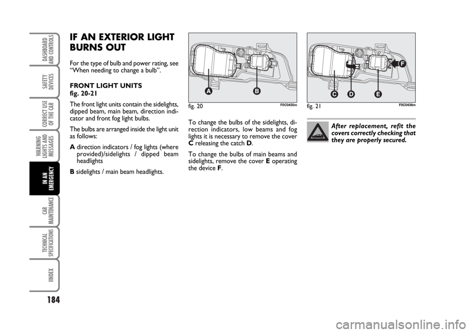
FRONT LIGHT UNITS
fig. 20-21
The front light units contain the sidelights,
dipped beam, main beam, direction indi-
cator and front fog light bulbs.
The bulbs are arranged inside the light unit
as follows:
Adirection indicators / fog lights (where
provided)/sidelights / dipped beam
headlights
Bsidelights / main beam headlights.To change the bulbs of the sidelights, di-
rection indicators, low beams and fog
lights it is necessary to remove the cover
Creleasing the catch D.
To change the bulbs of main beams and
sidelights, remove the cover Eoperating
the device F.
fig. 20F0C0435mfig. 21F0C0436m
After replacement, refit the
covers correctly checking that
they are properly secured.
Page 186 of 274
185
WARNING
LIGHTS AND
MESSAGES
CAR
MAINTENANCE
TECHNICAL
SPECIFICATIONS
INDEX
DASHBOARD
AND CONTROLS
SAFETY
DEVICES
CORRECT USE
OF THE CAR
IN AN
EMERGENCY
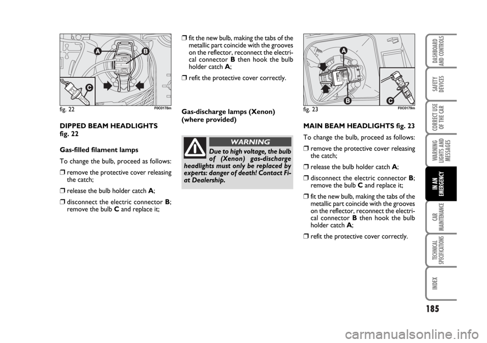
DIPPED BEAM HEADLIGHTS
fig. 22
Gas-filled filament lamps
To change the bulb, proceed as follows:
❒remove the protective cover releasing
the catch;
❒release the bulb holder catch A;
❒disconnect the electric connector B;
remove the bulb Cand replace it;Gas-discharge lamps (Xenon)
(where provided)
MAIN BEAM HEADLIGHTS fig. 23
To change the bulb, proceed as follows:
❒remove the protective cover releasing
the catch;
❒release the bulb holder catch A;
❒disconnect the electric connector B;
remove the bulb Cand replace it;
❒fit the new bulb, making the tabs of the
metallic part coincide with the grooves
on the reflector, reconnect the electri-
cal connector Bthen hook the bulb
holder catch A;
❒refit the protective cover correctly.
fig. 22F0C0178mfig. 23F0C0179m
Due to high voltage, the bulb
of (Xenon) gas-discharge
headlights must only be replaced by
experts: danger of death! Contact Fi-
at Dealership.
WARNING
❒fit the new bulb, making the tabs of the
metallic part coincide with the grooves
on the reflector, reconnect the electri-
cal connector Bthen hook the bulb
holder catch A;
❒refit the protective cover correctly.
Page 187 of 274
186
WARNING
LIGHTS AND
MESSAGES
CAR
MAINTENANCE
TECHNICAL
SPECIFICATIONS
IINDEX
DASHBOARD
AND CONTROLS
SAFETY
DEVICES
CORRECT USE
OF THE CAR
IN AN
EMERGENCY
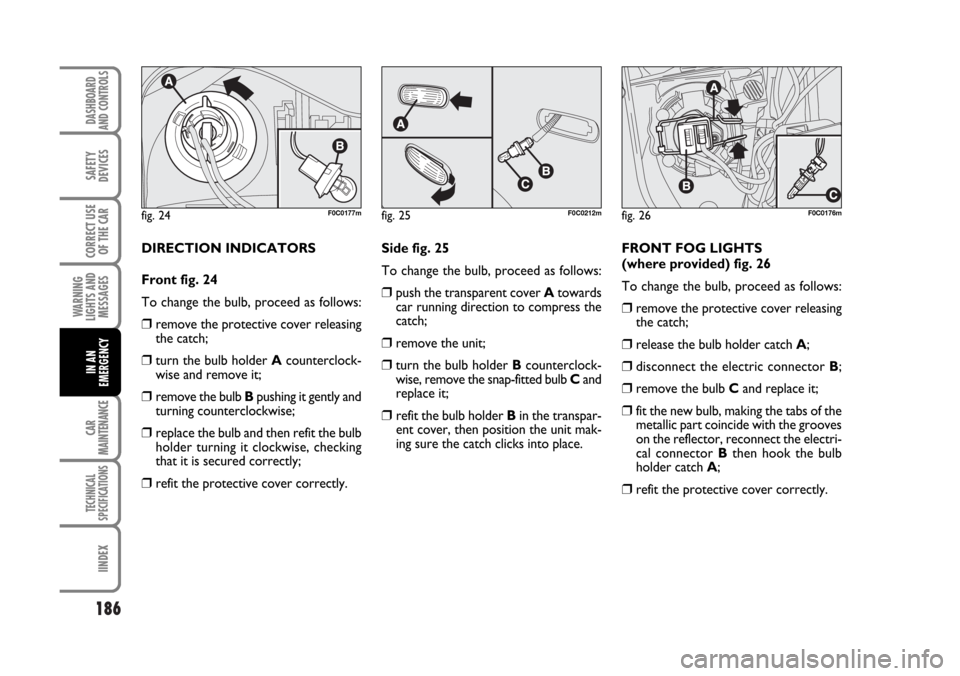
DIRECTION INDICATORS
Front fig. 24
To change the bulb, proceed as follows:
❒remove the protective cover releasing
the catch;
❒turn the bulb holder Acounterclock-
wise and remove it;
❒remove the bulb Bpushing it gently and
turning counterclockwise;
❒replace the bulb and then refit the bulb
holder turning it clockwise, checking
that it is secured correctly;
❒refit the protective cover correctly.Side fig. 25
To change the bulb, proceed as follows:
❒push the transparent cover Atowards
car running direction to compress the
catch;
❒remove the unit;
❒turn the bulb holder Bcounterclock-
wise, remove the snap-fitted bulb Cand
replace it;
❒ refit the bulb holder Bin the transpar-
ent cover, then position the unit mak-
ing sure the catch clicks into place.FRONT FOG LIGHTS
(where provided) fig. 26
To change the bulb, proceed as follows:
❒remove the protective cover releasing
the catch;
❒release the bulb holder catch A;
❒disconnect the electric connector B;
❒remove the bulb Cand replace it;
❒fit the new bulb, making the tabs of the
metallic part coincide with the grooves
on the reflector, reconnect the electri-
cal connector Bthen hook the bulb
holder catch A;
❒refit the protective cover correctly.
fig. 24F0C0177mfig. 25F0C0212mfig. 26F0C0176m
Page 188 of 274
187
WARNING
LIGHTS AND
MESSAGES
CAR
MAINTENANCE
TECHNICAL
SPECIFICATIONS
INDEX
DASHBOARD
AND CONTROLS
SAFETY
DEVICES
CORRECT USE
OF THE CAR
IN AN
EMERGENCY
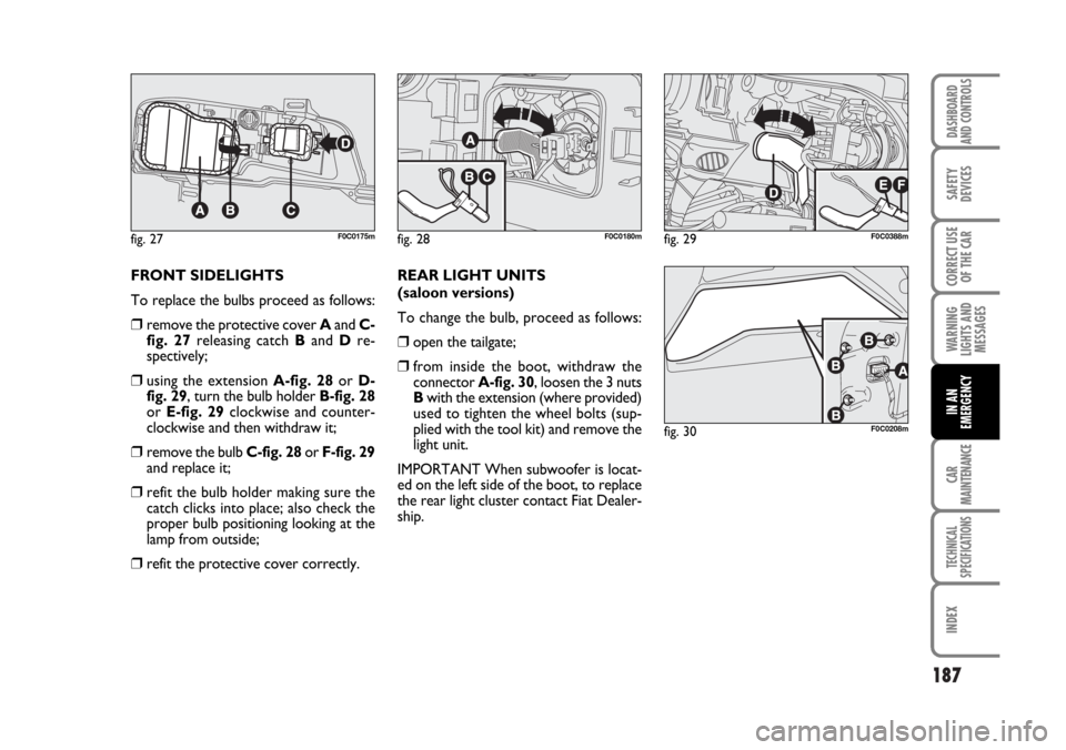
FRONT SIDELIGHTS
To replace the bulbs proceed as follows:
❒remove the protective cover Aand C-
fig. 27releasing catch Band Dre-
spectively;
❒using the extension A-fig. 28or D-
fig. 29, turn the bulb holder B-fig. 28
or E-fig. 29clockwise and counter-
clockwise and then withdraw it;
❒remove the bulb C-fig. 28or F-fig. 29
and replace it;
❒refit the bulb holder making sure the
catch clicks into place; also check the
proper bulb positioning looking at the
lamp from outside;
❒refit the protective cover correctly.REAR LIGHT UNITS
(saloon versions)
To change the bulb, proceed as follows:
❒open the tailgate;
❒from inside the boot, withdraw the
connector A-fig. 30, loosen the 3 nuts
Bwith the extension (where provided)
used to tighten the wheel bolts (sup-
plied with the tool kit) and remove the
light unit.
IMPORTANT When subwoofer is locat-
ed on the left side of the boot, to replace
the rear light cluster contact Fiat Dealer-
ship.
fig. 27F0C0175mfig. 28F0C0180mfig. 29F0C0388m
fig. 30F0C0208m
Page 189 of 274
188
WARNING
LIGHTS AND
MESSAGES
CAR
MAINTENANCE
TECHNICAL
SPECIFICATIONS
IINDEX
DASHBOARD
AND CONTROLS
SAFETY
DEVICES
CORRECT USE
OF THE CAR
IN AN
EMERGENCY
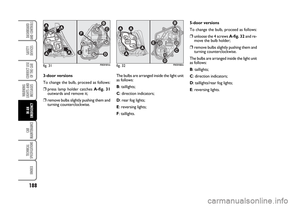
3-door versions
To change the bulb, proceed as follows:
❒press lamp holder catches A-fig. 31
outwards and remove it;
❒remove bulbs slightly pushing them and
turning counterclockwise.The bulbs are arranged inside the light unit
as follows:
B: taillights;
C: direction indicators;
D: rear fog lights;
E: reversing lights;
F: taillights.
fig. 31F0C0181mfig. 32F0C0182m
5-door versions
To change the bulb, proceed as follows:
❒unloose the 4 screws A-fig. 32and re-
move the bulb holder;
❒ remove bulbs slightly pushing them and
turning counterclockwise.
The bulbs are arranged inside the light unit
as follows:
B: taillights;
C: direction indicators;
D: taillights/rear fog lights;
E: reversing lights.
Page 190 of 274
189
WARNING
LIGHTS AND
MESSAGES
CAR
MAINTENANCE
TECHNICAL
SPECIFICATIONS
INDEX
DASHBOARD
AND CONTROLS
SAFETY
DEVICES
CORRECT USE
OF THE CAR
IN AN
EMERGENCY
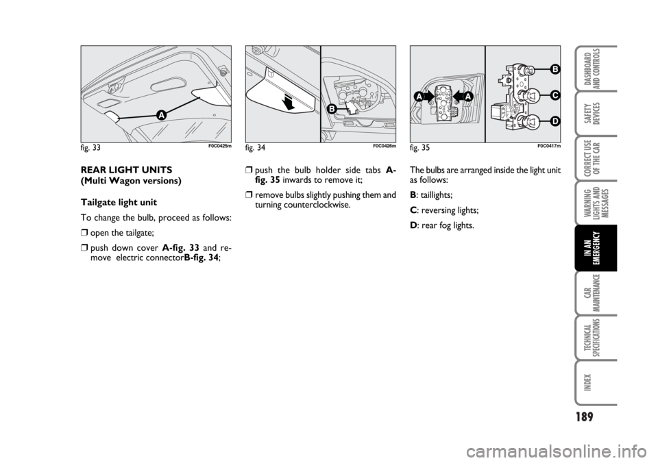
REAR LIGHT UNITS
(Multi Wagon versions)
Tailgate light unit
To change the bulb, proceed as follows:
❒open the tailgate;
❒ push down cover A-fig. 33and re-
move electric connectorB-fig. 34;
fig. 33F0C0425m
❒push the bulb holder side tabs A-
fig. 35inwards to remove it;
❒ remove bulbs slightly pushing them and
turning counterclockwise.
fig. 34F0C0426mfig. 35F0C0417m
The bulbs are arranged inside the light unit
as follows:
B: taillights;
C: reversing lights;
D: rear fog lights.
Page 191 of 274
190
WARNING
LIGHTS AND
MESSAGES
CAR
MAINTENANCE
TECHNICAL
SPECIFICATIONS
IINDEX
DASHBOARD
AND CONTROLS
SAFETY
DEVICES
CORRECT USE
OF THE CAR
IN AN
EMERGENCY
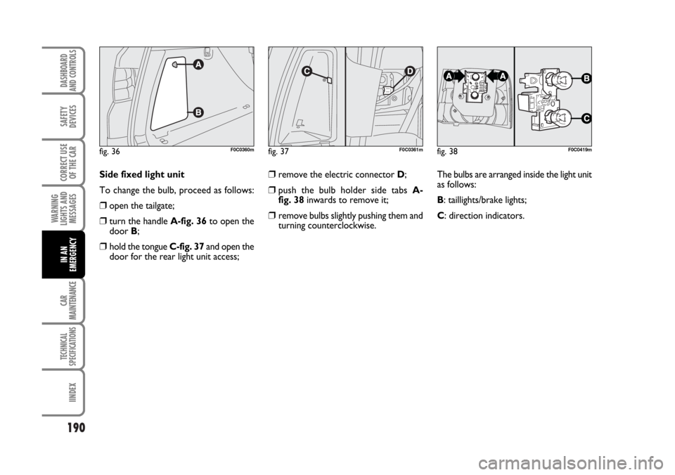
fig. 36F0C0360mfig. 37F0C0361mfig. 38F0C0419m
Side fixed light unit
To change the bulb, proceed as follows:
❒open the tailgate;
❒turn the handle A-fig. 36to open the
door B;
❒hold the tongue C-fig. 37and open the
door for the rear light unit access;
❒remove the electric connector D;
❒push the bulb holder side tabs A-
fig. 38inwards to remove it;
❒ remove bulbs slightly pushing them and
turning counterclockwise.The bulbs are arranged inside the light unit
as follows:
B: taillights/brake lights;
C: direction indicators.
Page 192 of 274
191
WARNING
LIGHTS AND
MESSAGES
CAR
MAINTENANCE
TECHNICAL
SPECIFICATIONS
INDEX
DASHBOARD
AND CONTROLS
SAFETY
DEVICES
CORRECT USE
OF THE CAR
IN AN
EMERGENCY
ADDITIONAL BRAKING LIGHT
(THIRD STOP)
IMPORTANT To replace the additional
braking lights (third stop) contact a Fiat
Dealership.
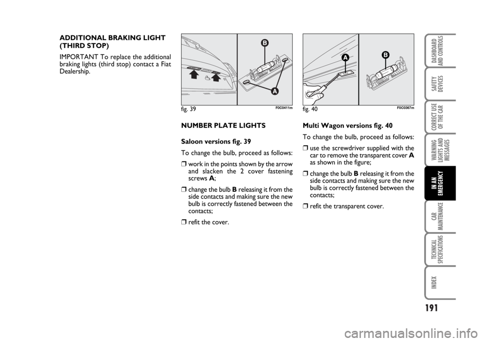
NUMBER PLATE LIGHTS
Saloon versions fig. 39
To change the bulb, proceed as follows:
❒work in the points shown by the arrow
and slacken the 2 cover fastening
screws A;
❒change the bulb Breleasing it from the
side contacts and making sure the new
bulb is correctly fastened between the
contacts;
❒refit the cover.
fig. 39F0C0411mfig. 40F0C0367m
Multi Wagon versions fig. 40
To change the bulb, proceed as follows:
❒use the screwdriver supplied with the
car to remove the transparent cover A
as shown in the figure;
❒change the bulb Breleasing it from the
side contacts and making sure the new
bulb is correctly fastened between the
contacts;
❒refit the transparent cover.
Page 193 of 274
192
WARNING
LIGHTS AND
MESSAGES
CAR
MAINTENANCE
TECHNICAL
SPECIFICATIONS
IINDEX
DASHBOARD
AND CONTROLS
SAFETY
DEVICES
CORRECT USE
OF THE CAR
IN AN
EMERGENCY
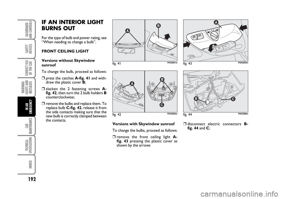
IF AN INTERIOR LIGHT
BURNS OUT
For the type of bulb and power rating, see
“When needing to change a bulb”.
FRONT CEILING LIGHT
Versions without Skywindow
sunroof
To change the bulb, proceed as follows:
❒press the catches A-fig. 41and with-
draw the plastic cover B;
❒slacken the 2 fastening screws A-
fig. 42, then turn the 2 bulb holders B
counterclockwise;
❒remove the bulbs and replace them. To
replace bulb C-fig. 42, release it from
the side contacts making sure that the
new bulb is correctly clamped between
the contacts.
Versions with Skywindow sunroof
To change the bulbs, proceed as follows:
❒remove the front ceiling light A-
fig. 43pressing the plastic cover as
shown by the arrows
❒disconnect electric connectors B-
fig. 44and C;
fig. 41F0C0201m
fig. 42F0C0202m
fig. 43F0C0253m
fig. 44F0C0398m
Page 194 of 274
193
WARNING
LIGHTS AND
MESSAGES
CAR
MAINTENANCE
TECHNICAL
SPECIFICATIONS
INDEX
DASHBOARD
AND CONTROLS
SAFETY
DEVICES
CORRECT USE
OF THE CAR
IN AN
EMERGENCY
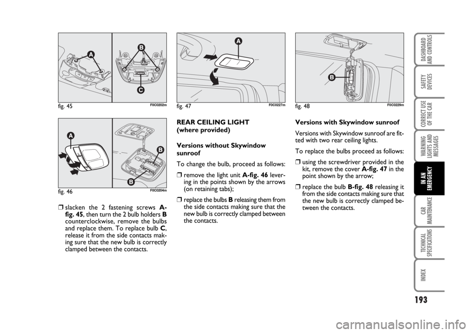
❒slacken the 2 fastening screws A-
fig. 45, then turn the 2 bulb holders B
counterclockwise, remove the bulbs
and replace them. To replace bulb C,
release it from the side contacts mak-
ing sure that the new bulb is correctly
clamped between the contacts.REAR CEILING LIGHT
(where provided)
Versions without Skywindow
sunroof
To change the bulb, proceed as follows:
❒remove the light unit A-fig. 46lever-
ing in the points shown by the arrows
(on retaining tabs);
❒replace the bulbs Breleasing them from
the side contacts making sure that the
new bulb is correctly clamped between
the contacts.Versions with Skywindow sunroof
Versions with Skywindow sunroof are fit-
ted with two rear ceiling lights.
To replace the bulbs proceed as follows:
❒using the screwdriver provided in the
kit, remove the cover A-fig. 47in the
point shown by the arrow;
❒replace the bulb B-fig. 48releasing it
from the side contacts making sure that
the new bulb is correctly clamped be-
tween the contacts.
fig. 45F0C0202m
fig. 46F0C0204m
fig. 47F0C0227mfig. 48F0C0229m