check engine FIAT TEMPRA 1988 Service And Workshop Manual
[x] Cancel search | Manufacturer: FIAT, Model Year: 1988, Model line: TEMPRA, Model: FIAT TEMPRA 1988Pages: 171, PDF Size: 18.05 MB
Page 88 of 171
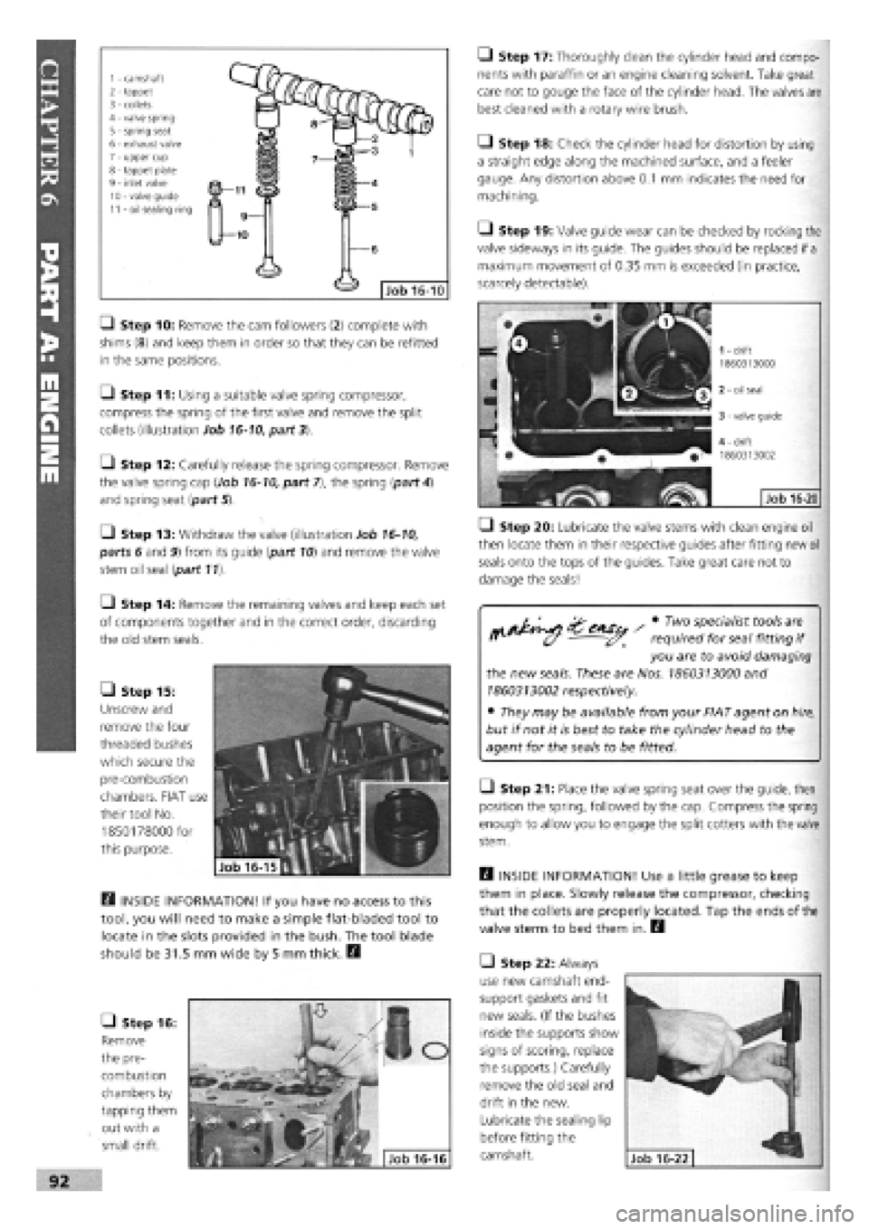
1 - camshaft 2 - tappet 3 - collets 4 - valve spring 5
-
spring seat 6 - exhaust valve 7 - upper cup 8 - tappet plate 9 - inlet valve 10 - valve guide 11 - oil sealing ring
• Step 10: Remove the cam followers (2) complete with
shims
(8)
and keep them in order so that they can be refitted
in the same positions.
O Step 11: Using a suitable valve spring compressor,
compress the spring of the first valve and remove the split
collets (illustration Job
16-10,
part 3).
[J Step 12: Carefully release the spring compressor. Remove
the valve spring cap (Job
16-10,
part 7), the spring {part
4)
and spring seat {part 5).
•
Step 13: Withdraw the valve (illustration Job
16-10,
parts 6 and 9) from its guide {part
10)
and remove the valve
stem oil seal {part 11).
Q Step 14: Remove the remaining valves and keep each set
of components together and in the correct order, discarding
the old stem seals.
• Step 15:
Unscrew and
remove the four
threaded bushes
which secure the
pre-combustion
chambers. FIAT use
their tool No.
1850178000 for
this purpose.
Q INSIDE INFORMATION! If you have no access to this
tool, you will need to make a simple flat-bladed tool to
locate in the slots provided in the bush. The tool blade
should be 31.5 mm wide by 5 mm thick. B
• Step 16:
Remove
the pre-
combustion
chambers by
tapping them
out with a
small drift.
Q Step 17: Thoroughly clean the cylinder head and compo-
nents with paraffin or an engine cleaning solvent. Take great
care not to gouge the face of the cylinder head. The valves are
best cleaned with a rotary wire brush.
• Step 18: Check the cylinder head for distortion by using
a straight edge along the machined surface, and a feeler
gauge. Any distortion above
0.1
mm indicates the need for
machining.
Q Step 19: Valve guide wear can be checked by rocking the
valve sideways in its guide. The guides should be replaced if
a
maximum movement of 0.35 mm is exceeded (in practice,
scarcely detectable).
• Step 20: Lubricate the valve stems with clean engine oil
then locate them in their respective guides after fitting new
oil
seals onto the tops of the guides. Take great care not to
damage the seals!
^ ^^iSu / * TW°
VfaliSt*?0lS
"'I
f' (y - required for seal fitting
if
you are to avoid damaging
the new
seals.
These are Nos.
1860313000
and
1860313002
respectively.
• They may be available from your FIAT agent on
hire,
but if not it is best to take the cylinder head to the
agent for the seals to be fitted.
Q Step 21: Place the valve spring seat over the guide, then
position the spring, followed by the cap. Compress the spring
enough to allow you to engage the split cotters with the valve
stem.
Q INSIDE INFORMATION! Use a little grease to keep
them in place. Slowly release the compressor, checking
that the collets are properly located. Tap the ends of the
valve stems to bed them in. B
• Step 22: Always
use new camshaft end-
support gaskets and fit
new seals. (If the bushes
inside the supports show
signs of scoring, replace
the supports.) Carefully
remove the old seal and
drift in the new.
Lubricate the sealing lip
before fitting the
camshaft.
Page 91 of 171
Q Step 2: Before starting the engine, make sure all your
electrical connections are sound and your fuel, oil and coolant
connections are correct and secure.
Q Step 3: Run the engine to working temperature and then
allow to cool. Re-check all fluid levels.
Job 20. Diesel engine.
Mountings - replacement.
See
Job
12
and Job
18,
Step 20
Job 21. Diesel engine/
transmission (removed from car)
- separation.
Q Step 1: Remove the starter motor.
• Step 2: On the turbo version, undo the flange bolts see
Job
18,
Step 16A and withdraw the drive-shaft extension, if
still
fitted.
Q Step 3: Unbolt and remove the rear engine plate and the
gearbox, being careful to support the gearbox weight as it is
withdrawn.
Job 22. Diesel engine/
transmission (removed from car)
- reconnection.
Q Step 1: Before proceeding, check the condition of the
clutch and
its release mechanism. Make sure the driven plate
is
properly centred on the flywheel
-
see PART B: TRANS-
MISSION.
Q Step 2: Now reverse the order of separation, but be
careful when
engaging the gearbox input shaft with the
clutch
driven plate that you don't 'hang' its weight on the
splines.
Also,
see
Job 11.
Job 23. Diesel engine -
dismantling.
This Job should
be read in conjunction with Job 5 The
engines are
broadly similar although the information given in
this Job takes
priority for diesel engines. It is MOST
IMPORTANT that you read the FACT FILE on page 84.
SAFETY FIRST!
•
The inside
of diesel engines are particularly filthy
places!
•
Old diesel
oil
is
carcinogenic!
•
Wear suitable
impervious gloves!
I
• Step 1: Remove the timing belt and cylinder head. See
Jobs
13
and 14.
Q Step 2: Remove the alternator, water pump and
thermostat housing distribution pipe.
• Step 3: Remove the crankshaft timing belt sprocket.
Q INSIDE INFORMATION! Note that the bolt securing
the crankshaft sprocket has a left-hand thread and must
be undone clockwise. D
• Step 4: Unbolt the timing belt tensioner and idler pulleys.
• Step 5: Remove the injection pump sprocket.
Q INSIDE INFORMATION! You will need two FIAT tools
for this operation. One (No. 1860473000) is to prevent
the sprocket from turning when undoing the nut, and
the other (extractor No. 1842128000) to pull the sprocket
from the injection pump shaft. Alternatively it may be
possible to improvise a means of preventing sprocket
rotation, and a suitable three-leg puller may be carefully
used to withdraw the sprocket. Take care not to lose the
pump shaft Woodruff key. B
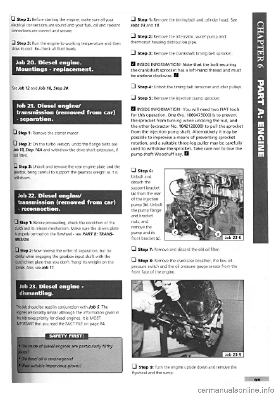
• Step 6:
Unbolt and
detach the
support bracket
(a) from the rear
of the injection
pump (b). Unbolt
the pump flange
and bracket
nuts, and
remove the
pump and its
front bracket (c).
• Step 7: Remove and discard the old oil filter.
Step 8: Remove the crankcase breather, the low-oil-
pressure switch and the oil pressure gauge sensor from the
front face of the engine.
• Step 9: Turn the engine upside down and remove the
flywheel and the sump.
Page 93 of 171
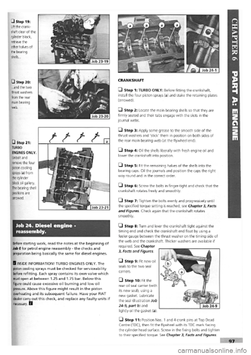
CRANKSHAFT
• Step 1: TURBO ONLY: Before fitting the crankshaft,
install the four piston sprays (a) and stake the retaining plates
(arrowed).
Q Step 2: Locate the main bearing shells so that they are
firmly seated and their tabs engage with the slots in the
journal webs.
• Step 3: Apply some grease to the smooth side of the
thrust washers and 'stick' them in position on both sides of
the rear main bearing web (at the flywheel end).
• Step 4: Oil the shells liberally with fresh engine oil and
lower the crankshaft into position.
• Step 5: Fit the remaining halves of the shells into the
bearing caps. Oil the journals and position the caps the right
way round and in the correct order.
• Step 6: Screw the bolts in finger-tight and check that the
crankshaft rotates freely and smoothly.
Q Step 7: Tighten the bolts evenly and progressively until
the specified torque setting is reached, see Chapter
3,
Facts
and Figures. Check again that the crankshaft rotates
smoothly.
• Step 19:
Lift
the crank-
shaft clear of the
cylinder block,
retrieve the
other halves of
the
bearing
shells...
• Step 20:
...and
the two
thrust
washers
from
the rear
main bearing
web.
• Step 21:
TURBO
ENGINES ONLY.
Unbolt and
remove
the four
piston cooling
sprays
(a) from
the
cylinder
block oil gallery.
The
bearing shell
positions are
arrowed.
Job 24. Diesel engine -
reassembly.
Before starting work, read the notes at the beginning of
Job 6 for petrol engine reassembly
-
the checks and
preparation being basically the same for diesel engines.
H INSIDE INFORMATION! TURBO ENGINES ONLY. The
piston cooling sprays must be checked for serviceability
before refitting. Each spray contains its own valve which
must
open at between 1.25 and 1.75 bar. Below this
figure could cause excessive oil burning and low oil
pressure. Above this figure might result in the piston
overheating and its subsequent failure. Have your FIAT
dealer carry out this check, and replace any faulty units if
necessary. Q
• Step 9: Fit new oil
seals to the two seal
carriers.
• Step 10: Fit the
rear oil seal carrier (with
its new seal), using a
new gasket. Lubricate
the seal (illustration Job
24-9,
part b) and
lightly oil the gasket (a).
• Step 11: Position Nos. 1 and 4 crank pins at Top Dead
Centre (TDC), then fit the flywheel with its TDC mark facing
the cylinder head surface. Screw in the fixing bolts and tighten
to their specified torque. See Chapter
3,
Facts and Figures
Job 23-21
Q Step 8: Turn and lever the crankshaft tight against the
timing end and check the crankshaft end float by using a
feeler gauge between the thrust washer on the timing side of
the web and the crankshaft. Thicker washers are available if
required. See Chapter
3, Facts and Figures.
Page 94 of 171
U Step 12: Fit a new seal to the front cover/oil pump
assembly, unless a new pump is being fitted, and install with a
new gasket, lightly oiling both gasket and seal. Align the cover
with the sump support plate.
PISTON CONNECTING RODS ASSEMBLIES
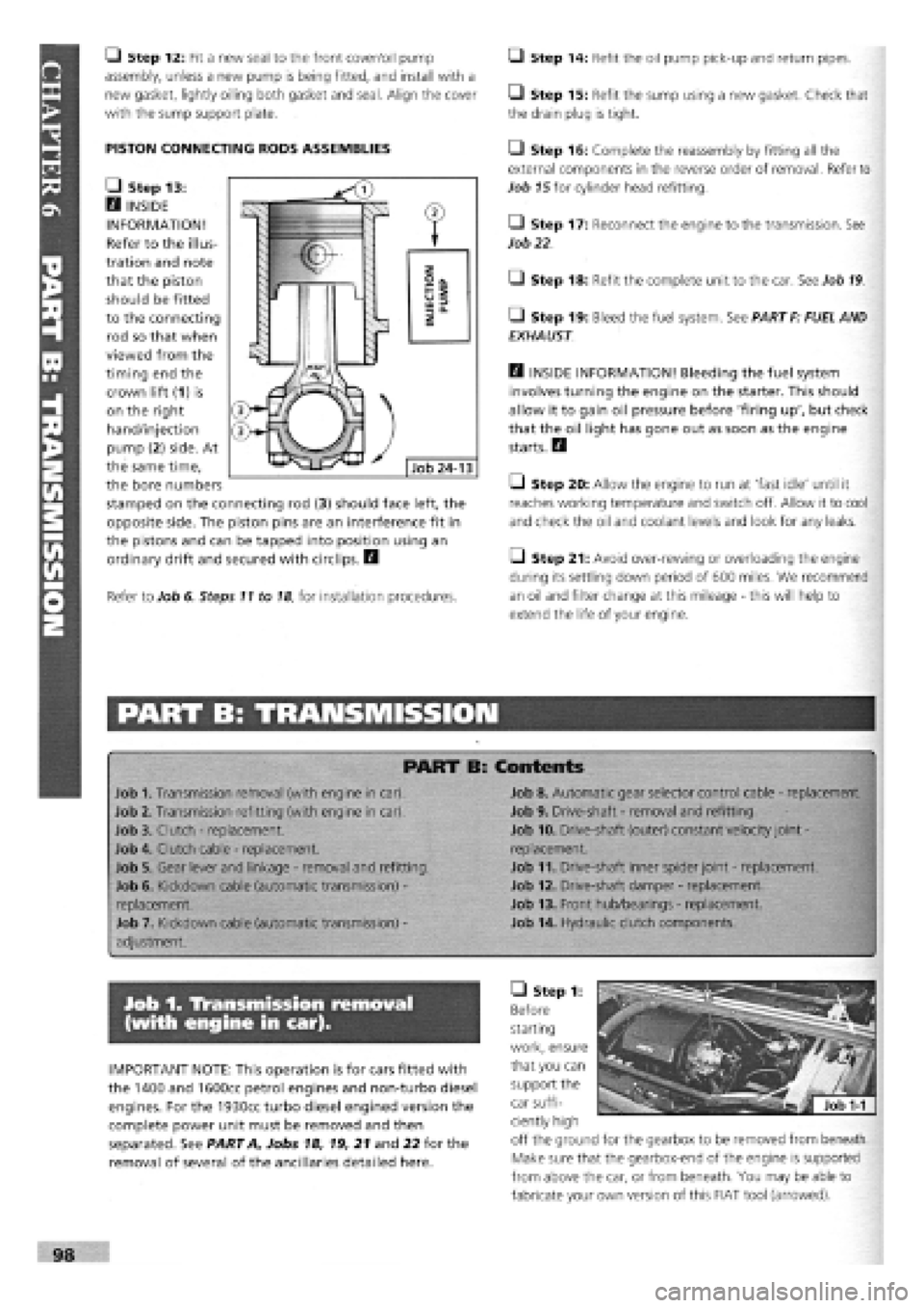
• Step 13:
H INSIDE
INFORMATION!
Refer to the illus-
tration and note
that the piston
should be fitted
to the connecting
rod so that when
viewed from the
timing end the
crown lift (1) is
on the right
hand/injection
pump (2) side. At
the same time,
the bore numbers
stamped on the connecting rod (3) should face left, the
opposite side. The piston pins are an interference fit in
the pistons and can be tapped into position using an
ordinary drift and secured with circlips. H
Refer to Job 6. Steps 11 to
18,
for installation procedures.
Q Step 14: Refit the oil pump pick-up and return pipes.
• Step 15: Refit the sump using a new gasket. Check that
the drain plug is tight.
• Step 16: Complete the reassembly by fitting all the
external components in the reverse order of removal. Refer to
Job
15
for cylinder head refitting.
• Step 17: Reconnect the engine to the transmission. See
Job
22
• Step 18: Refit the complete unit to the car. See Job
19
• Step 19: Bleed the fuel system. See PART F: FUEL AND
EXHAUST
Q INSIDE INFORMATION! Bleeding the fuel system
involves turning the engine on the starter. This should
allow it to gain oil pressure before 'firing up', but check
that the oil light has gone out as soon as the engine
starts. H
Q Step 20: Allow the engine to run at 'fast idle' until it
reaches working temperature and switch off. Allow it to cool
and check the oil and coolant levels and look for any leaks.
Q Step 21: Avoid over-rewing or overloading the engine
during its settling down period of 600 miles. We recommend
an oil and filter change at this mileage
-
this will help to
extend the life of your engine.
PART B: TRANSMISSION
PART B: Contents
Job 1. Transmission removal (with engine in car).
Job 2. Transmission refitting (with engine in car).
Job 3. Clutch
-
replacement.
Job 4. Clutch cable
-
replacement.
Job 5. Gear lever and linkage
-
removal and refitting.
Job 6. Kickdown cable (automatic transmission)
-
replacement.
Job 7. Kickdown cable (automatic transmission)
-
adjustment.
Job 8. Automatic gear selector control cable
-
replacement.
Job 9. Drive-shaft
-
removal and refitting.
Job 10. Drive-shaft (outer) constant velocity joint
-
replacement.
Job 11. Drive-shaft inner spider joint
-
replacement.
Job 12. Drive-shaft damper
-
replacement.
Job 13. Front hub/bearings
-
replacement.
Job 14. Hydraulic clutch components.
Job 1. Transmission removal
(with engine in car).
IMPORTANT NOTE: This operation is for cars fitted with
the 1400 and 1600cc petrol engines and non-turbo diesel
engines. For the 1930cc turbo diesel engined version the
complete power unit must be removed and then
separated. See PART A, Jobs 18, 19, 21 and 22 for the
removal of several of the ancillaries detailed here.
• Step 1:
Before
starting
work, ensure
that you can
support the
car suffi-
ciently high
off the ground for the gearbox to be removed from beneath.
Make sure that the gearbox-end of the engine is supported
from above the car, or from beneath. You may be able to
fabricate your own version of this FIAT tool (arrowed).
Page 96 of 171
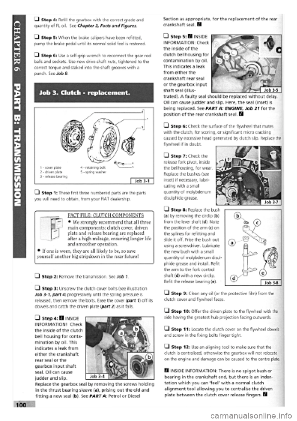
• Step 4: Refill the gearbox with the correct grade and
quantity of FL oil. See Chapter
3,
Facts and Figures.
Section as appropriate, for the replacement of the rear
crankshaft seal. B
—1 Step 5: When the brake calipers have been refitted,
pump the brake pedal until its normal solid feel is restored.
• Step 6: Use a self-grip wrench to reconnect the gear rod
balls and sockets. Use new drive-shaft nuts, tightened to the
correct torque and staked into the shaft grooves with a
punch. See Job 9.
Job 3. Clutch - replacement.
1 - cover plate 2 - driven plate 3 - release bearing
4 - retaining bolt 5 - spring washer
;
Job 3-1
Q Step 1: These first three numbered parts are the parts
you will need to obtain, from your FIAT dealership.
FACT FILE: CLUTCH COMPONENTS
• We strongly recommend that all three
main components: clutch cover, driven
plate and release bearing are replaced
after a high mileage, ensuring longer life
and smoother operation.
• If one is worn, they are all likely to be, so save
yourself another big stripdown in the near future!
LI Step 2: Remove the transmission. See Job 1.
• Step 3: Unscrew the clutch cover bolts (see illustration
Job
3-1,
part 4) progressively until the spring pressure is
released, then remove the bolts. Ease the cover (part 1) off its
dowels and catch the driven plate {part 2) as it falls.
• Step 6: Check the surface of the flywheel that mates
with the clutch, for scoring, or significant micro cracking
caused by excessive head generated by clutch slip. Replace the
flywheel if in doubt.
7ZJ
• Step 7: Check the
release fork pivot, inside
the bellhousing, for wear
Replace the bushes (see
inset) if necessary, lubri-
cating with a small
quantity of molybdenum
disulphide grease.
• Step 8: Replace the bush
(a) by removing the circlip (b)
from the lever shaft (d). Note
the position of the arm (c) on
the splines for refitting and
slide it off. Prise the bush out
using a screwdriver. Lubricate
the new bush with a small
quantity of molybdenum disul-
phide grease and install. Refit
the arm to the fork control
shaft (d) with a new circlip.
Refit the release bearing (e).
• Step 9: Clean any oil (or the protective film) from the
clutch cover and flywheel faces.
• Step 10: Offer the driven plate to the flywheel with the
side having the greatest hub projection facing outwards.
• Step 11: Locate the clutch cover on the flywheel dowels
and screw in the fixing bolts finger tight.
• Step 12: Use an aligning tool to make sure that the
clutch is centralised, otherwise the gearbox will not relocate
on the engine and damage can be caused to the centre plate.
B INSIDE INFORMATION: There is no spigot bush or
bearing in the crankshaft end, but there is an inden-
tation which you can 'feel' with a normal clutch
alignment tool allowing you to centralise the driven
plate between the clutch cover release fingers. B
• Step 5: B INSIDE
INFORMATION: Check
the inside of the
clutch bellhousing for
contamination by oil.
This indicates a leak
from either the
crankshaft rear seal
or the gearbox input
shaft seal (illus-
trated). A faulty seal should be replaced without delay.
Oil can cause judder and slip. Here, the seal (inset) is
being replaced. See PART A: ENGINE, Job 21 for the
position of the rear crankshaft seal. B
• Step 4: B INSIDE
INFORMATION! Check
the inside of the clutch
bell housing for conta-
mination by oil. This
indicates a leak from
either the crankshaft
rear seal or the
gearbox input shaft
seal. Oil can cause
judder and slip.
Replace the gearbox seal by removing the screws holding
in the thrust bearing sleeve (a), prising out the old and
fitting a new seal (b). See PART A: Petrol or Diesel
Page 98 of 171
Job 8. Automatic gear selector
control cable - replacement.
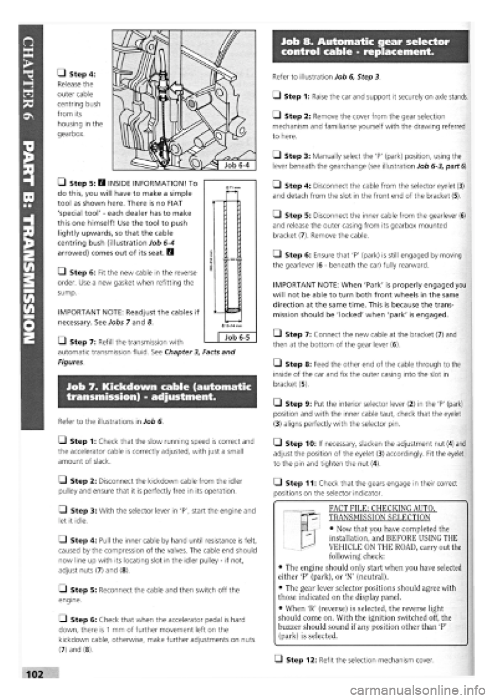
• Step 4:
Release the
outer cable
centring bush
from its
housing in the
gearbox.
• Step 5: H INSIDE INFORMATION! To
do this, you will have to make a simple
tool as shown here. There is no FIAT
'special tool'
-
each dealer has to make
this one himself! Use the tool to push
lightly upwards, so that the cable
centring bush (illustration Job
6-4
arrowed) comes out of its seat. B
• Step 6: Fit the new cable in the reverse
order. Use a new gasket when refitting the
sump.
IMPORTANT NOTE: Readjust the cables if
necessary. See Jobs 7 and 8.
Q Step 7: Refill the transmission with
automatic transmission fluid. See Chapter
3,
Facts and
Figures.
Job 7. Kickdown cable (automatic
transmission) - adjustment.
Refer to the illustrations in Job 6.
Q Step 1: Check that the slow running speed is correct and
the accelerator cable is correctly adjusted, with just a small
amount of slack.
Q Step 2: Disconnect the kickdown cable from the idler
pulley and ensure that it is perfectly free in its operation.
• Step 3: With the selector lever in 'P', start the engine and
let it idle.
Q Step 4: Pull the inner cable by hand until resistance is felt,
caused by the compression of the valves. The cable end should
now line up with its locating slot in the idler pulley
-
if not,
adjust nuts (7) and (8).
[_l Step 5: Reconnect the cable and then switch off the
engine.
• Step 6: Check that when the accelerator pedal is hard
down, there is
1
mm of further movement left on the
kickdown cable, otherwise, make further adjustments on nuts
(7) and (8).
Refer to illustration Job 6, Step 3.
• Step 1: Raise the car and support it securely on axle stands.
• Step 2: Remove the cover from the gear selection
mechanism and familiarise yourself with the drawing referred
to here.
Q Step 3: Manually select the 'P' (park) position, using the
lever beneath the gearchange (see illustration Job
6-3,
part
6).
• Step 4: Disconnect the cable from the selector eyelet (3)
and detach from the slot in the front end of the bracket (5).
Q Step 5: Disconnect the inner cable from the gearlever (6)
and release the outer casing from its gearbox mounted
bracket (7). Remove the cable.
Q Step 6: Ensure that 'P' (park) is still engaged by moving
the gearlever (6
-
beneath the car) fully rearward.
IMPORTANT NOTE: When 'Park' is properly engaged you
will not be able to turn both front wheels in the same
direction at the same time. This is because the trans-
mission should be 'locked' when 'park' is engaged.
• Step 7: Connect the new cable at the bracket (7) and
then at the bottom of the gear lever (6).
• Step 8: Feed the other end of the cable through to the
inside of the car and fix the outer casing into the slot in
bracket (5).
• Step 9: Put the interior selector lever (2) in the 'P' (park)
position and with the inner cable taut, check that the eyelet
(3) aligns perfectly with the selector pin.
• Step 10: If necessary, slacken the adjustment nut (4) and
adjust the position of the eyelet (3) accordingly. Fit the eyelet
to the pin and tighten the nut (4).
• Step 11: Check that the gears engage in their correct
positions on the selector indicator.
T "I FACT FILE: CHECKING AUTOT
qp- TRANSMISSION SELECTION
EL
-
• Now that you have completed the
installation, and BEFORE USING THE
VEHICLE ON THE ROAD, carry out the
following check:
• The engine should only start when you have selected
either 'P' (park), or 'N' (neutral).
• The gear lever selector positions should agree with
those indicated on the display panel.
• When 'R' (reverse) is selected, the reverse light
should come on. With the ignition switched off, the
buzzer should sound if any position other than 'P'
(park) is selected.
Q Step 12: Refit the selection mechanism cover.
0
Job 6-5
Page 99 of 171
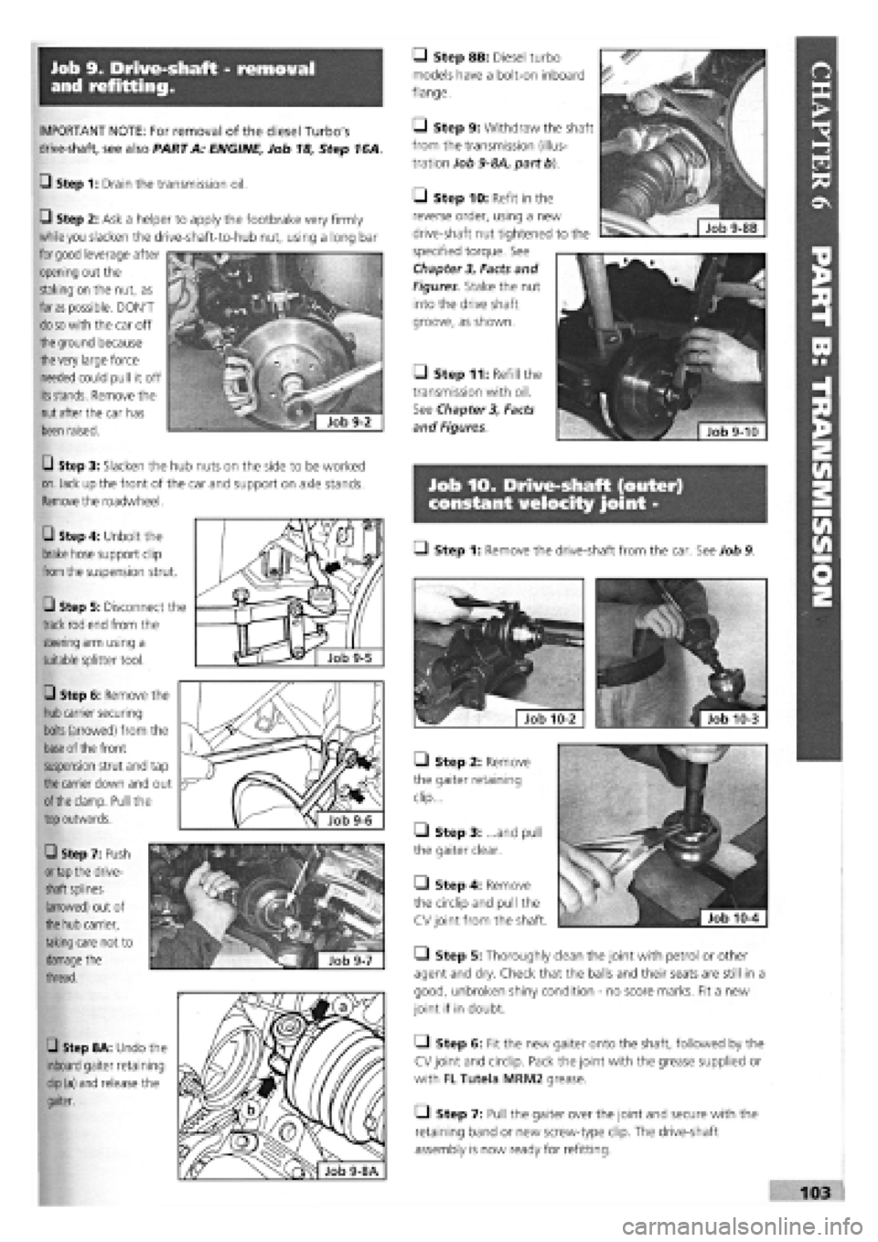
Job 9. Drive-shaft - removal
and refitting.
IMPORTANT NOTE: For removal of the diesel Turbo's
drive-shaft, see also PART A: ENGINE, Job 18, Step 16A.
G Step 1: Drain the transmission oil.
• Step 8B: Diesel turbo
models have a bolt-on inboard
flange.
• Step 9: Withdraw the shaft
from the transmission (illus-
tration Job
9-8A,
part b).
G Step 2: Ask a helper to apply the footbrake very firmly
while
you
slacken the drive-shaft-to-hub nut, using a long bar
for
good
leverage after
opening out the
staking on the nut, as
far
as
possible. DON'T
do so
with the car off
the
ground because
the
very large force
needed could pull it off
its stands.
Remove the
nut
after the car has
been raised.
Job 10. Drive-shaft (outer)
constant velocity joint -
G Step 8A: Undo the
inboard
gaiter retaining
clip
(a) and release the
gaiter.
• Step 11: Refill the
transmission with oil.
See Chapter
3,
Facts
and Figures.
G Step 3: Slacken the hub nuts on the side to be worked
on.
Jack up the front of the car and support on axle stands.
Remove the roadwheel.
G Step 6: Remove the
hub
carrier securing
bolts
(arrowed) from the
base
of the front
suspension strut and tap
the
carrier down and out
of the
clamp. Pull the
top
outwards.
G Step 7: Push
or tap
the drive-
shaft
splines
(arrowed) out of
the hub
carrier,
taking
care not to
damage
the
thread.
Q Step 1: Remove the drive-shaft from the car. See Job 9. G Step 4: Unbolt the
brake hose support clip
from
the suspension strut.
G Step 5: Disconnect the
track rod end from the
steering arm using a
suitable splitter tool.
• Step 2: Remove
the gaiter retaining
clip...
Q Step 3: ...and pull
the gaiter clear.
• Step 4: Remove
the circlip and pull the
CV joint from the shaft.
Q Step 5: Thoroughly clean the joint with petrol or other
agent and dry. Check that the balls and their seats are still in a
good, unbroken shiny condition
-
no score marks. Fit a new
joint if in doubt.
• Step 6: Fit the new gaiter onto the shaft, followed by the
CV joint and circlip. Pack the joint with the grease supplied or
with FL Tutela MRM2 grease.
Q Step 7: Pull the gaiter over the joint and secure with the
retaining band or new screw-type clip. The drive-shaft
assembly is now ready for refitting.
• Step 10: Refit in the
reverse order, using a new
drive-shaft nut tightened to the
specified torque. See
Chapter
3,
Facts and
Figures Stake the nut
into the drive shaft
groove, as shown.
Page 100 of 171
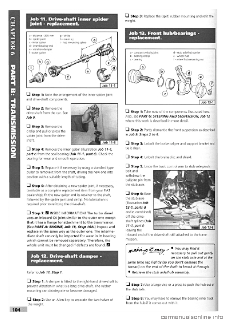
Job 11. Drive-shaft inner spider
joint - replacement.
• Step 3: Replace the (split) rubber mounting and refit the
weight.
Job 13. Front hub/bearings -
replacement.
Job 11-1
a - distance - 305 mm b - spider joint c - inner gaiter d - inner bearing seal e
-
vibration damper f
-
outer gaiter
g - circlip h - outer u.j. i - hub mounting spline
• Step 1: Note the arrangement of the inner spider joint
and drive-shaft components.
Q Step 2: Remove the
drive-shaft from the car. See
Job 9.
• Step 3: Remove the
circlip and pull or press the
spider joint from the drive-
shaft.
• Step 4: Remove the inner gaiter (illustration Job
11-1,
part c) from the seal bearing (Job
11-1,
partd). Check the
bearing for wear and smooth operation.
Q Step 5: Replace it if necessary by using a standard type
puller to remove it from the shaft, driving the new one into
position with a suitable length of tubing.
Q Step 6: After obtaining a new spider joint, if necessary,
(available as a complete replacement item from your FIAT
dealership), fit the new gaiter and its retainer to the shaft,
followed by the spider joint and circlip. No lubrication is
required prior to refitting the drive-shaft.
• Step 7: E9 INSIDE INFORMATION! The turbo diesel
uses an inboard CV joint similar to the outer one except
that it has a flange for attachment to the transmission.
(See PART A: ENGINE, Job 18, Step 16A ) Inspect and
replace in the same way as the outer one. The interme-
diate shaft can only be inspected for wear in its bearing
which cannot be removed separately. Therefore, the
whole unit must be changed if defects are found. Q
Job 12. Drive-shaft damper -
replacement.
Refer to Job
11,
Step 1
Q Step 1: A damper is fitted to the right-hand drive-shaft to
prevent vibration in what is a long drive-shaft. The rubber
mounting can disintegrate or become damaged.
Q Step 2: Use an Allen key to separate the two halves of
the weight.
s * You ™yfind *
" U ' necessary to pull out
gently
on the stub axle and at
the
same time tap lightly (so you don't damage the
thread) on the end of the shaft to knock it through.
• Retrieve the stub axle/hub assembly.
Q Step 7: Use a large vice or a press to push the hub out of
the stub axle.
• Step 8: You may have to remove the bearing inner track
from the hub if it comes out with it.
• Step 2: Partly dismantle the front suspension as described
in Job 9. Steps 2 to 6.
• Step 3: Unbolt the brake caliper and support bracket and
tie it clear.
• Step 1: Take note of the components illustrated here.
Also, see PART G: STEERING AND SUSPENSION, Job
12
where this work is described in more detail.
Q Step 4: Unbolt the brake disc and shield.
• Step 5: Undo the track control arm to stub axle pinch
bolt and
withdraw the
balljoint pin from
the stub axle.
• Step 6: Ease
the stub axle
(illustration Job
13-1,
parts d
and c, combined)
off the drive-
shaft splines (Job
11-1,
parti)
leaving the
inboard end of the
mission.
drive-shaft still attached to the trans-
Page 105 of 171
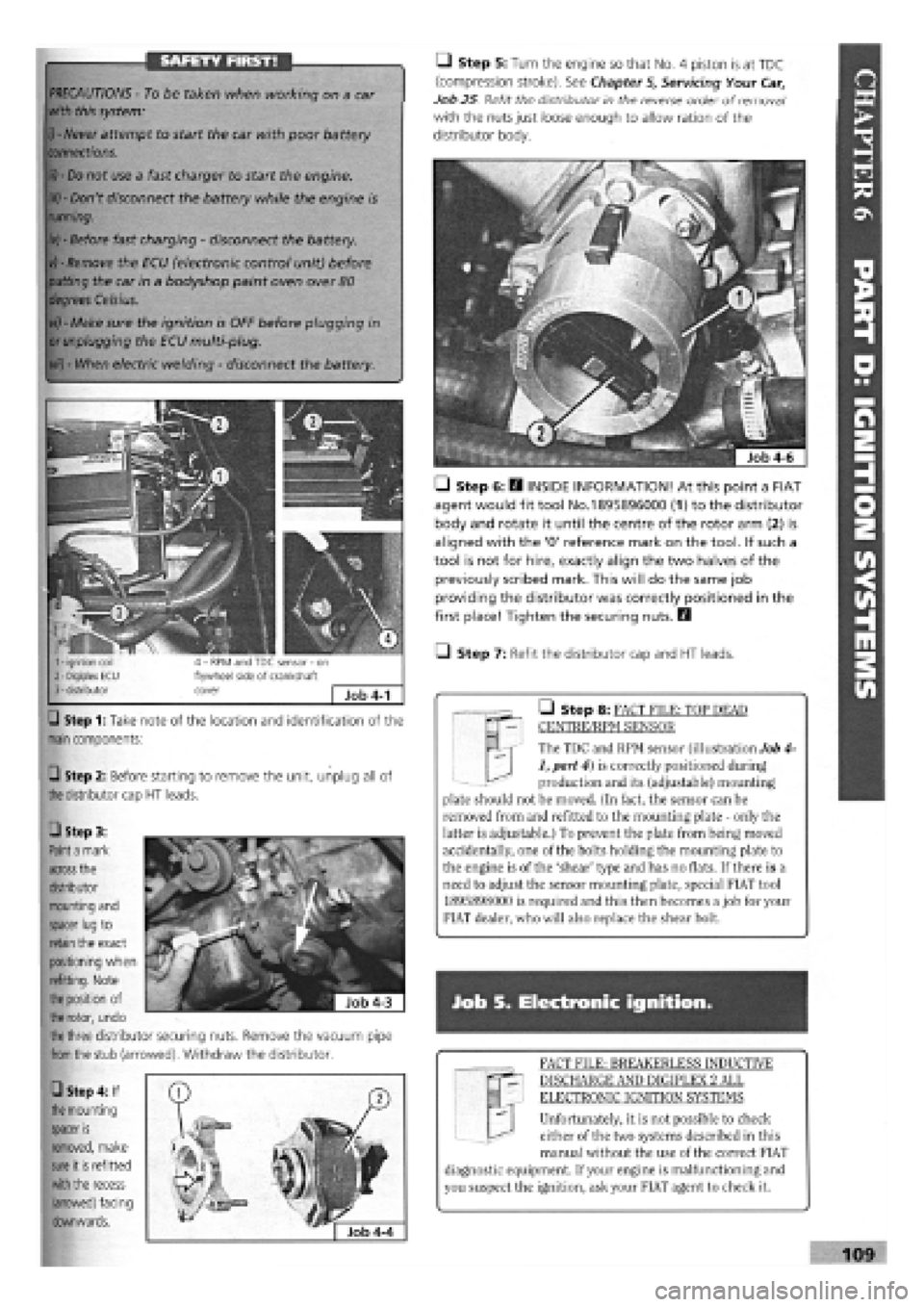
SAFETY FIRST!
Step 1: Take note of the location and identification of the
main
components:
Q Step 2: Before starting to remove the unit, unplug all of
the
distributor cap
HT
leads.
M | The TDC and RPM sensor (illustration Job 4-
1, part 4) is correctly positioned during
production and its (adjustable) mounting
plate should not be moved. (In fact, the sensor can be
removed from and refitted to the mounting plate - only the
latter is adjustable.) To prevent the plate from being moved
accidentally, one of the bolts holding the mounting plate to
the engine is of the 'shear' type and has no flats. If there is a
need to adjust the sensor mounting plate, special FIAT tool
1895898000 is required and this then becomes a job for your
FIAT dealer, who will also replace the shear bolt.
• Step 8: FACT FILE: TOP DEAD
CENTRE/RPM SENSOR
PRECAUTIONS -
To be taken when working on a car
with this system:
i) - Never
attempt to start the car with poor battery
connections.
ii) - Do
not use a fast charger to start the engine.
iii) -
Don't disconnect the battery while the engine is
running.
iv) -
Before fast charging
-
disconnect the battery.
vj - Remove
the ECU (electronic control unit) before
putting
the car in a bodyshop paint oven over
80
degrees Celsius.
vi) -
Make sure the ignition is OFF before plugging in
or unplugging
the ECU multi-plug.
vii) -
When electric welding
-
disconnect the battery.
Q Step 5: Turn the engine so that No. 4 piston is at TDC
(compression stroke). See Chapter
5,
Servicing Your Car,
Job 25 Refit the distributor in the reverse order of removal1
with the nuts just loose enough to allow ration of the
distributor body.
• Step 6: E3 INSIDE INFORMATION! At this point a FIAT
agent would fit tool No.1895896000 (1) to the distributor
body and rotate it until the centre of the rotor arm (2) is
aligned with the '0' reference mark on the tool. If such a
tool is not for hire, exactly align the two halves of the
previously scribed mark. This will do the same job
providing the distributor was correctly positioned in the
first place! Tighten the securing nuts. Q
• Step 7: Refit the distributor cap and HT leads.
Job S. Electronic ignition.
FACT FILE: BREAKERLESS INDUCTIVE
DISCHARGE AND DIGIPLEX 2 ALL
ELECTRONIC IGNITION SYSTEMS
Unfortunately, it is not possible to check
either of the two systems described in this
manual without the use of the correct FIAT
diagnostic equipment. If your engine is malfunctioning and
you suspect the ignition, ask your FIAT agent to check it.
109
• Step 3:
Paint a
mark
across
the
distributor
mounting and
spacer lug
to
retain
the exact
positioning when
refitting. Note
the position
of
the rotor,
undo
the three
distributor securing nuts. Remove the vacuum pipe
from the
stub (arrowed). Withdraw the distributor.
• Step 4: If
the
mounting
spacer
is
removed, make
sure
it
is
refitted
with the
recess
(arrowed) facing
downwards.
Page 106 of 171
PART E: ELECTRICAL ARID INSTRUMENTS
PART E: Contents
Job 1. Alternator
-
removal and refitting. Job 10. Rear light cluster
-
replacement.
Job 2. Starter motor
-
removal and refitting. Job 11. Side repeater indicators
-
replacement.
Job 3. Instrument panel
-
removal and refitting. Job 12. Number plate light
-
replacement.
Job 4. Speedometer cable
-
replacement. Job 13. Interior/courtesy light
-
removal and refitting.
Job 5. Windscreen wiper motor
-
replacement. Job 14. Fuel gauge sender unit
-
removal and refitting.
Job 6. Hatchback wiper motor
-
replacement. Job 15. Central locking
-
replacement of components.
Job 7. Windscreen washer pump
-
replacement. Job 16. Electric windows
-
replacement of components.
Job 8. Radio aerial
-
replacement. Job 17. Diesel engines. Glow plugs
-
checking and
Job 9. Headlight cluster
-
replacement. replacement.
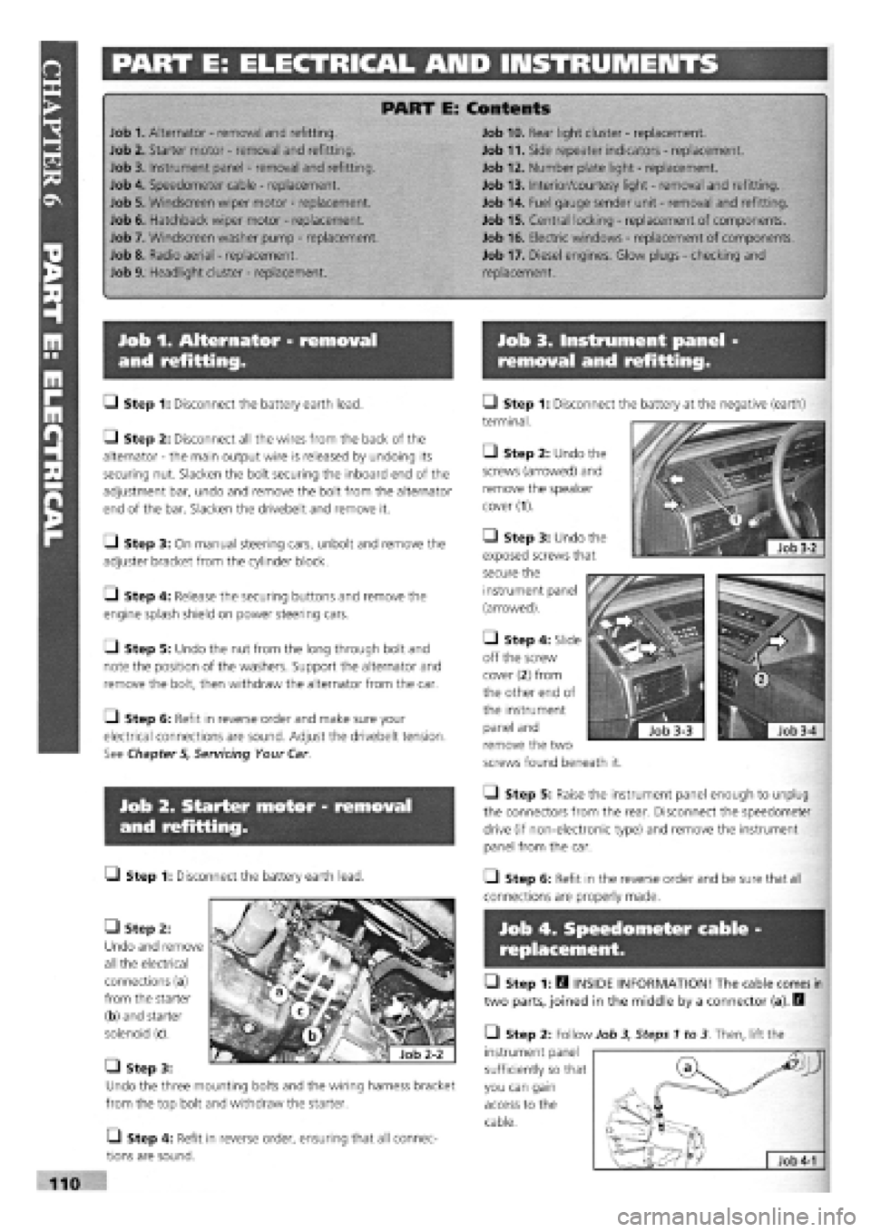
Job 1. Alternator - removal
and refitting.
Job 3. Instrument panel -
removal and refitting.
• Step 1: Disconnect the battery earth lead.
Q Step 2: Disconnect all the wires from the back of the
alternator
-
the main output wire is released by undoing its
securing nut. Slacken the bolt securing the inboard end of the
adjustment bar, undo and remove the bolt from the alternator
end of the bar. Slacken the drivebelt and remove it.
Q Step 3: On manual steering cars, unbolt and remove the
adjuster bracket from the cylinder block.
Q Step 4: Release the securing buttons and remove the
engine splash shield on power steering cars.
Q Step 5: Undo the nut from the long through bolt and
note the position of the washers. Support the alternator and
remove the bolt, then withdraw the alternator from the car.
Q Step 6: Refit in reverse order and make sure your
electrical connections are sound. Adjust the drivebelt tension.
See Chapter 5, Servicing Your Car
• Step 1: Disconnect
terminal.
• Step 2: Undo the
screws (arrowed) and
remove the speaker
cover (1).
Job 2. Starter motor - removal
and refitting.
• Step 1: Disconnect the battery earth lead.
• Step 2:
Undo and remove
all the electrical
connections (a)
from the starter
(b) and starter
solenoid (c).
Q Step 4: Refit in reverse order, ensuring that all connec-
tions are sound.
Q Step 5: Raise the instrument panel enough to unplug
the connectors from the rear. Disconnect the speedometer
drive (if non-electronic type) and remove the instrument
panel from the car.
Q Step 6: Refit in the reverse order and be sure that all
connections are properly made.
Job 4. Speedometer cable
replacement.
• Step 1: H INSIDE INFORMATION! The cable comes in
two parts, joined in the middle by a connector (a). Q
• Step 2: Follow Job 3, Steps 1 to 3 Then, lift the
instrument panel
sufficiently so that
you can gain
access to the
cable.
^Jj
Job
4-1
the battery at the negative (earth)
• Step 3: Undo the
exposed screws that
secure the
instrument panel
(arrowed).
• Step 4: Slide
off the screw
cover
(2)
from
the other end of
the instrument
panel and
remove the two
screws found beneath it.
• Step 3:
Undo the three mounting bolts and the wiring harness bracket
from the top bolt and withdraw the starter.