FIAT UNO 1983 Service Repair Manual
Manufacturer: FIAT, Model Year: 1983, Model line: UNO, Model: FIAT UNO 1983Pages: 303, PDF Size: 10.36 MB
Page 121 of 303
speakers, central door locking or power
operated windows, the electrical leads must be
disconnected and withdrawn through the
flexible duct before the door hinges are
unbolted. Disconnection will require removal of
the door trim panel as described in Section 11.
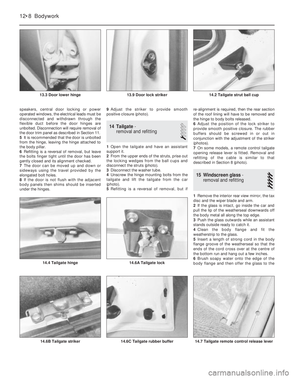
5It is recommended that the door is unbolted
from the hinge, leaving the hinge attached to
the body pillar.
6Refitting is a reversal of removal, but leave
the bolts finger tight until the door has been
gently closed and its alignment checked.
7The door can be moved up and down or
sideways using the travel provided by the
elongated bolt holes.
8If the door is not flush with the adjacent
body panels then shims should be inserted
under the hinges.9Adjust the striker to provide smooth
positive closure (photo).
14 Tailgate-
removal and refitting
1
1Open the tailgate and have an assistant
support it.
2From the upper ends of the struts, prise out
the locking wedges from the ball cups and
disconnect the struts (photo).
3Disconnect the washer tube.
4Unscrew the hinge mounting bolts from the
tailgate and lift the tailgate from the car
(photo).
5Refitting is a reversal of removal, but ifre-alignment is required, then the rear section
of the roof lining will have to be removed and
the hinge to body bolts released.
6Adjust the position of the lock striker to
provide smooth positive closure. The rubber
buffers should be screwed in or out in
conjunction with the adjustment of the striker
(photos).
7On some models, a remote control tailgate
opening release lever is fitted. Removal and
refitting of the cable is similar to that
described in Section 8 (photo).
15 Windscreen glass-
removal and refitting
5
1Remove the interior rear view mirror, the tax
disc and the wiper blade and arm.
2If the glass is intact, go inside the car and
pull the lip of the weatherseal downwards off
the body metal all along the top edge.
3Push the glass outwards while an assistant
stands outside ready to catch it.
4Clean the body flange and fit the
weatherstrip to the glass.
5Insert a length of strong cord in the body
flange groove of the weatherseal so that the
ends of the cord cross over at the centre of
the bottom run and hang out a few inches.
6Brush soapy water onto the edge of the
body flange and then offer the glass to the
12•8 Bodywork
14.7 Tailgate remote control release lever14.6C Tailgate rubber buffer14.6B Tailgate striker
14.6A Tailgate lock14.4 Tailgate hinge
14.2 Tailgate strut ball cup13.9 Door lock striker13.3 Door lower hinge
Page 122 of 303
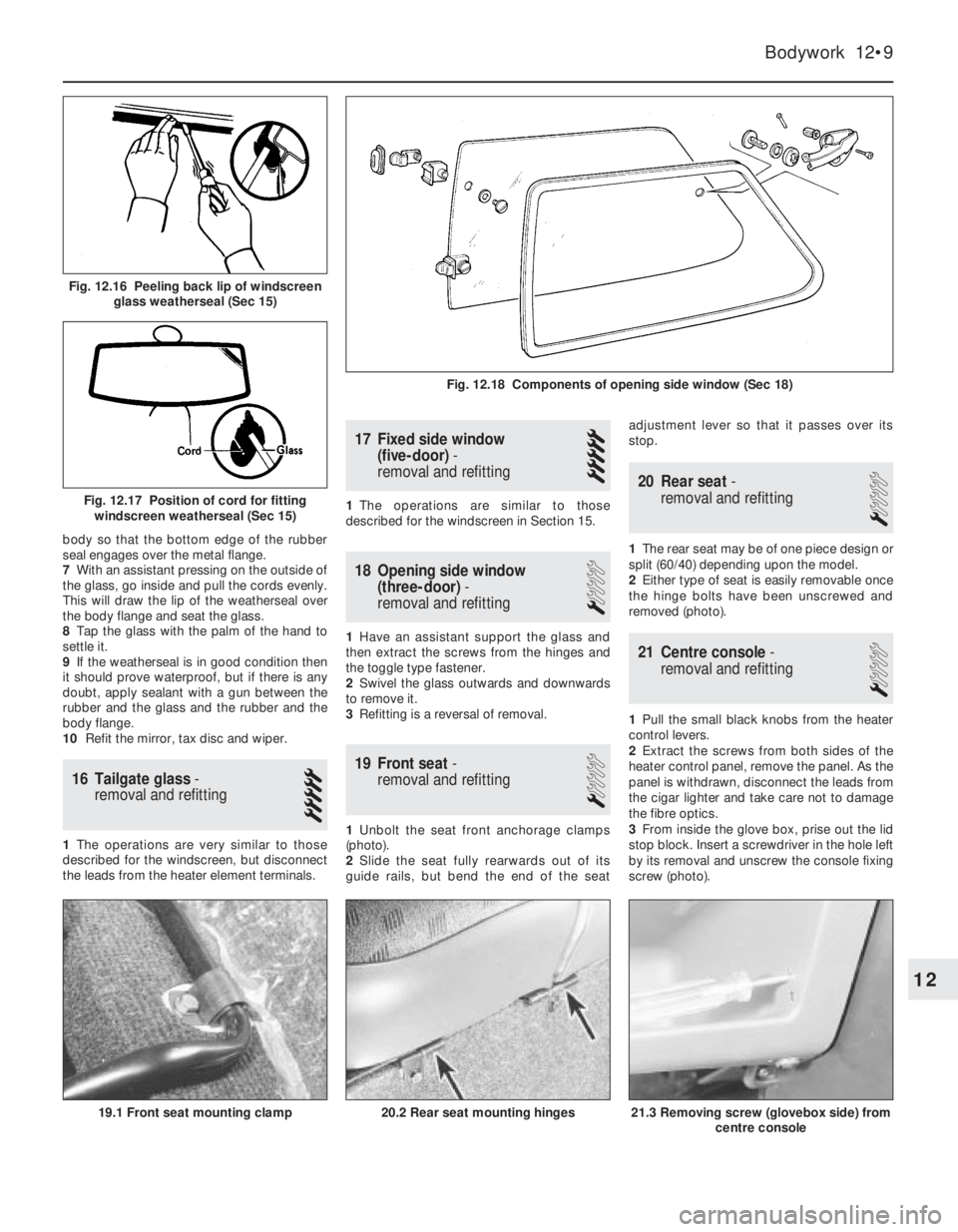
body so that the bottom edge of the rubber
seal engages over the metal flange.
7With an assistant pressing on the outside of
the glass, go inside and pull the cords evenly.
This will draw the lip of the weatherseal over
the body flange and seat the glass.
8Tap the glass with the palm of the hand to
settle it.
9If the weatherseal is in good condition then
it should prove waterproof, but if there is any
doubt, apply sealant with a gun between the
rubber and the glass and the rubber and the
body flange.
10Refit the mirror, tax disc and wiper.
16 Tailgate glass-
removal and refitting
5
1The operations are very similar to those
described for the windscreen, but disconnect
the leads from the heater element terminals.
17 Fixed side window
(five-door)-
removal and refitting
5
1The operations are similar to those
described for the windscreen in Section 15.
18 Opening side window
(three-door)-
removal and refitting
1
1Have an assistant support the glass and
then extract the screws from the hinges and
the toggle type fastener.
2Swivel the glass outwards and downwards
to remove it.
3Refitting is a reversal of removal.
19 Front seat-
removal and refitting
1
1Unbolt the seat front anchorage clamps
(photo).
2Slide the seat fully rearwards out of its
guide rails, but bend the end of the seatadjustment lever so that it passes over its
stop.
20 Rear seat-
removal and refitting
1
1The rear seat may be of one piece design or
split (60/40) depending upon the model.
2Either type of seat is easily removable once
the hinge bolts have been unscrewed and
removed (photo).
21 Centre console-
removal and refitting
1
1Pull the small black knobs from the heater
control levers.
2Extract the screws from both sides of the
heater control panel, remove the panel. As the
panel is withdrawn, disconnect the leads from
the cigar lighter and take care not to damage
the fibre optics.
3From inside the glove box, prise out the lid
stop block. Insert a screwdriver in the hole left
by its removal and unscrew the console fixing
screw (photo).
Bodywork 12•9
Fig. 12.18 Components of opening side window (Sec 18)
Fig. 12.17 Position of cord for fitting
windscreen weatherseal (Sec 15)
Fig. 12.16 Peeling back lip of windscreen
glass weatherseal (Sec 15)
21.3 Removing screw (glovebox side) from
centre console20.2 Rear seat mounting hinges19.1 Front seat mounting clamp
12
Page 123 of 303
4Reach up behind the facia panel on the side
opposite to the glove box and unscrew the
remaining console fixing screw.
5Withdraw the console downwards and
disconnect the fibre optics from their source.
6Refitting is a reversal of removal.
22 Facia panel-
removal and refitting
1
1Remove the instrument panel as described
in Chapter 9.
2Remove the steering wheel (Chapter 10). 3Disconnect the choke control lever and
cable from the facia panel as described in
Chapter 3.
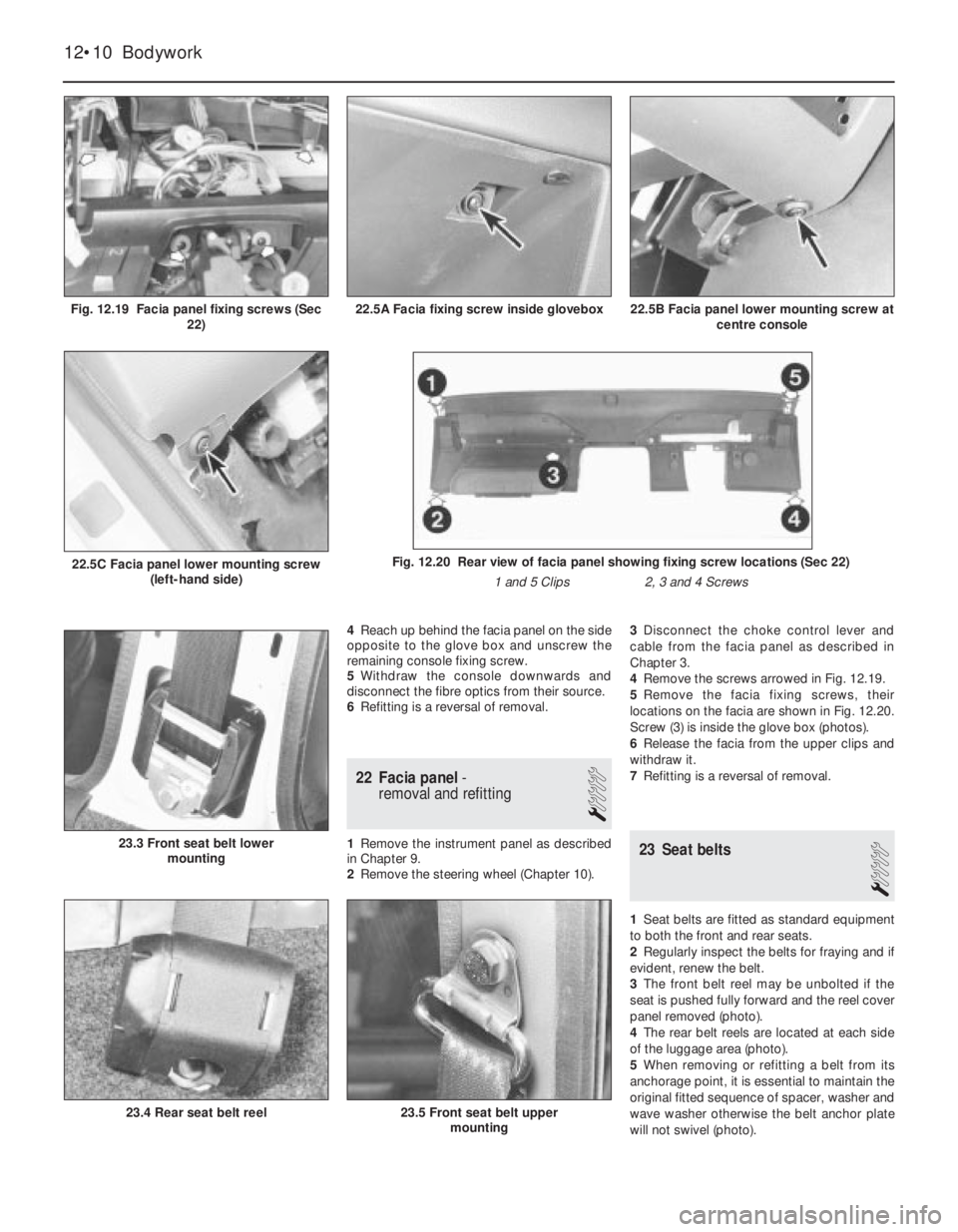
4Remove the screws arrowed in Fig. 12.19.
5Remove the facia fixing screws, their
locations on the facia are shown in Fig. 12.20.
Screw (3) is inside the glove box (photos).
6Release the facia from the upper clips and
withdraw it.
7Refitting is a reversal of removal.23 Seat belts
1
1Seat belts are fitted as standard equipment
to both the front and rear seats.
2Regularly inspect the belts for fraying and if
evident, renew the belt.
3The front belt reel may be unbolted if the
seat is pushed fully forward and the reel cover
panel removed (photo).
4The rear belt reels are located at each side
of the luggage area (photo).
5When removing or refitting a belt from its
anchorage point, it is essential to maintain the
original fitted sequence of spacer, washer and
wave washer otherwise the belt anchor plate
will not swivel (photo).
23.4 Rear seat belt reel
23.3 Front seat belt lower
mounting
12•10 Bodywork
23.5 Front seat belt upper
mounting
Fig. 12.20 Rear view of facia panel showing fixing screw locations (Sec 22)
1 and 5 Clips 2, 3 and 4 Screws22.5C Facia panel lower mounting screw
(left-hand side)
22.5B Facia panel lower mounting screw at
centre console22.5A Facia fixing screw inside gloveboxFig. 12.19 Facia panel fixing screws (Sec
22)
Page 124 of 303
24 Rear view mirrors
1
Interior
1The mirror may be removed after extracting
the fixing screws. The mirror is designed to
break off if struck.
Exterior
2The mirror is remotely controlled. To
remove the mirror, peel back the rubber cover
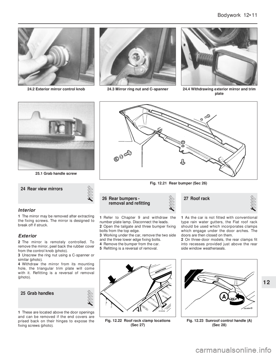
from the control knob (photo).
3Unscrew the ring nut using a C-spanner or
similar (photo).
4Withdraw the mirror from its mounting
hole, the triangular trim plate will come
with it. Refitting is a reversal of removal
(photo).
25 Grab handles
1
1These are located above the door openings
and can be removed if the end covers are
prised back on their hinges to expose the
fixing screws (photo).
26 Rear bumpers -
removal and refitting
1
1Refer to Chapter 9 and withdraw the
number plate lamp. Disconnect the leads.
2Open the tailgate and three bumper fixing
bolts from the top edge.
3Working under the car, remove the two side
and the three lower edge fixing bolts.
4Remove the bumper from the car.
5Refitting is a reversal of removal.
27 Roof rack
1
1As the car is not fitted with conventional
type rain water gutters, the Fiat roof rack
should be used which incorporates clamps
which engage under the door arches. The
doors are then closed on them.
2On three-door models, the rear clamps fit
into recesses provided just above the rear
side window weatherseals.
Bodywork 12•11
24.4 Withdrawing exterior mirror and trim
plate
25.1 Grab handle screw
24.3 Mirror ring nut and C-spanner24.2 Exterior mirror control knob
Fig. 12.23 Sunroof control handle (A)
(Sec 28)Fig. 12.22 Roof rack clamp locations
(Sec 27)
Fig. 12.21 Rear bumper (Sec 26)
12
Page 125 of 303
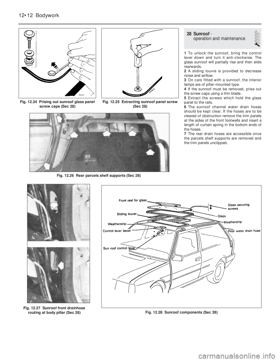
28 Sunroof-
operation and maintenance
1
1To unlock the sunroof, bring the control
lever down and turn it anti-clockwise. The
glass sunroof will partially rise and then slide
rearwards.
2A sliding louvre is provided to decrease
noise and airflow.
3On cars fitted with a sunroof, the interior
lamps are of pillar-mounted type.
4If the sunroof must be removed, prise out
the screw caps using a thin blade.
5Extract the screws which hold the glass
panel to the rails.
6The sunroof channel water drain hoses
should be kept clear. If the hoses are to be
cleared of obstruction remove the trim panels
at the sides of the front footwells and insert a
length of curtain spring in the bottom ends of
the hoses.
7The rear drain hoses are accessible once
the parcels shelf supports are removed and
the trim panels unclipped.
12•12 Bodywork
Fig. 12.28 Sunroof components (Sec 28)Fig. 12.27 Sunroof front drainhose
routing at body pillar (Sec 28)
Fig. 12.26 Rear parcels shelf supports (Sec 28)
Fig. 12.25 Extracting sunroof panel screw
(Sec 28)Fig. 12.24 Prising out sunroof glass panel
screw caps (Sec 28)
Page 126 of 303
13
Chapter 13 Supplement:
Revisions and information on later models
Introduction . . . . . . . . . . . . . . . . . . . . . . . . . . . . . . . . . . . . . . . . . . . 1
Specifications . . . . . . . . . . . . . . . . . . . . . . . . . . . . . . . . . . . . . . . . . 2
Routine maintenance - all models from June 1991 . . . . . . . . . . . 3
Engine 903 and 1299/1301 cc . . . . . . . . . . . . . . . . . . . . . . . . . . . . . 4
Sump pan sealing strips (903 cc engine) - modification
1299 cc engine - description
Rocker cover (903 cc engine) - removal
Cylinder head (903 cc engine) - refitting
Engine - 999 and 1108 cc (FIRE) . . . . . . . . . . . . . . . . . . . . . . . . . . 5
Part A: General
Description
Part B: Operations possible with engine in car
Valve clearances - adjustment
Timing belt - renewal
Camshaft - removal and refitting
Cylinder head - removal and refitting
Sump pan - removal and refitting
Oil pump - removal, checking and refitting
Pistons/connecting rods - removal and refitting
Pistons/connecting rods - separation and piston ring renewal
Engine/transmission mountings - renewal
Part C: Engine removal and dismantling
Method of removal - general
Engine/transmission - removal and separation
Dismantling - general
Complete dismantling
Examination and renovation
Part D: Engine reassembly and refitting
Reassembly - general
Complete reassembly
Engine/transmission - reconnection and refitting
Initial start-up after major overhaul
Engine 1301 cc Turbo ie.................................................................. 6
Part A: General
Description
Lubrication system - description
Part B: Operations possible with engine in car
Camshaft and camshaft carrier - removal and refitting
Cylinder head - removal and refitting
Piston rings
Engine mountings - renewal
Timing belt - renewal
Oil pump drivegear cover plate
Engine oil cooler - removal and refittingPart C: Engine removal, dismantling, reassembly and refitting
Engine/transmission - removal and separation
Engine - dismantling and reassembly
Engine/transmission - reconnection and refitting
Initial start-up after major overhaul
Engine 1372 cc ie and 1372 cc Turbo ie......................................... 7
Part A: General
Description
Maintenance
Part B: Operations possible with the engine in car
Valve clearances - checking and adjustment
Timing belt, tensioner and sprockets - removal and refitting
Camshaft front oil seal - renewal
Camshaft, housing and followers - removal and refitting
Camshaft housing, camshaft and cam followers - dismantling,
inspection and reassembly
Cylinder head (1372 cc ie engine) - removal and refitting
Cylinder head (1372 cc Turbo ie engine) - removal and refitting
Cylinder head - inspection and renovation
Crankshaft front oil seal - removal and renewal
Crankshaft rear oil seal - removal and renewal
Flywheel - removal, inspection and refitting
Sump - removal and refitting
Oil pump - removal, checking and refitting
Pistons/connecting rods - removal and refitting
Pistons/connecting rods - examination and renovation
Engine/transmission mountings - renewal
Part C: Engine removal and dismantling
Method of removal - general
1372 cc ie engine/transmission - removal and separation
1372 cc Turbo ie engine/transmission - removal and separation
Engine dismantling - general
Auxiliary shaft - removal, inspection and refitting
Engine - complete dismantling
Crankshaft and main bearings - removal
Engine components - examination and renovation
Part D: Engine reassembly
Reassembly - general
Crankshaft and main bearings - refitting
Pistons and connecting rods - refitting
Oil pump - refitting
Sump - refitting
Flywheel - refitting
Auxiliary shaft - refitting
Cylinder head - refitting
Timing belt and covers - refitting
Engine/transmission - reconnection and refitting
Initial start-up after major overhaul
13•1
Contents
Page 127 of 303
Cooling system................................................................................. 8
Part A: 999 cc engine
Description
Maintenance
Thermostat - removal and refitting
Coolant pump - removal and refitting
Part B: 1301 cc Turbo ie engine
Description
Part C: 1372 cc ie and 1372 cc Turbo ie engines
Description
Maintenance
Cooling system - draining, flushing and refilling
Radiator (and cooling fan) - removal and refitting
Thermostat - removal and refitting
Coolant pump - removal and refitting
Coolant pump/alternator drivebelt - checking, renewal and
tensioning
Part D: Heater unit later models
Heater unit - removal and refitting
Heater unit - dismantling and reassembly
Fuel and exhaust systems............................................................... 9
Part A: General
Unleaded fuel
Air cleaner modified types
Fuel pump (999 cc engine) - description, removal and
refitting
Fuel tank (999 cc engine)
Part B: Carburettor models
Carburettor (Weber 32 TLF) - description
Carburettor (Weber 32 TLF) - idle speed and mixture
Carburettor (Weber 32 TLF) - removal and refitting
Carburettor (Weber 32 TLF) - overhaul
Carburettor (Weber 30/32 DMTE) - general
Carburettor (Weber 30/32 DMTE) - overhaul
Carburettor (Weber 32 ICEV 61/250 and DMTE 30/32,
DMTE 30/150) - general
Carburettor (Solex C 30/32-CIC 8) - description
Part C: Bosch LE-2 Jetronic fuel injection system
Description
Maintenance
Fuel filter - renewal
Air cleaner element - renewal
Idle speed and mixture - adjustment
Fuel injection system - electrical tests
Fuel injection system - mechanical tests
Fuel injection system components - removal and
refitting
Throttle control linkage - general
Fuel tank - general
Part D: Bosch Mono-Jetronic fuel injection system
Description
Maintenance
Fuel filter - renewal
Air cleaner element - renewal
Idle speed and mixture adjustment
Accelerator control system - check and adjustment
Fuel system - depressurisation
Fuel pump and supply - system checks
Fuel pump - removal and refitting
Injector unit - removal and refitting
Intake air temperature sensor - removal and refitting
Fuel injector - removal and refitting
Electronic control unit (ECU) - removal and refitting
Inlet manifold - removal and refitting
Exhaust manifold - removal and refitting
Catalytic converter - general information
Fuel evaporation control system - generalPart E: Bosch L3.1/2 Jetronic fuel injection systems
Description
Fuel system - depressurisation
Maintenance
Fuel filter - renewal
Air cleaner element - renewal
Checks and adjustments
Injection system components - removal and refitting
Part G: Turbocharger system
Description
Precautions
Turbocharger (1301 cc ie engine) - removal and refitting
Turbocharger (1372 cc ie engine) - removal and refitting
Intercooler - removal and refitting
Injector cooling fan - removal and refitting
Fault finding - fuel injection system
Fault finding - turbocharger system
Ignition system................................................................................. 10
General
Ignition timing (all later models)
Breakerless ignition system - description
Distributor (breakerless type) - removal and refitting
Distributor (breakerless type) - overhaul
Breakerless ignition system components - testing
Microplex ignition system - description
Distributor (Microplex) - removal and refitting
Microplex ignition system components - testing
Digiplex 2 ignition system - description
Distributor (Digiplex 2) - removal and refitting
Spark plugs and HT leads - general
Fault finding - Microplex ignition system
Clutch................................................................................................ 11
Clutch pedal adjustment (cable clutch)
Hydraulic clutch - description
Maintenance (hydraulic clutch)
Clutch master cylinder - removal, overhaul and
refitting
Clutch operating cylinder - removal, overhaul and
refitting
Clutch hydraulic system - bleeding
Transmission.................................................................................... 12
Part A: 1301 cc Turbo ie engine
Description
Gearchange linkage - removal and refitting
Gearchange linkage (Antiskid models) - general
Final drive output shafts - description and oil seal
renewal
Part B: 1372 cc ie and 1372 cc Turbo ie engines
Description
Maintenance
Oil level - checking
Oil - renewal
Gearlever and linkages - general
Transmission - removal and refitting
Part C: 999 and 1108 cc with C514 type transmission
Description
Maintenance
Driveshafts........................................................................................ 13
Inboard joint boots (non-Turbo models, September 1987 on) -
modification
Intermediate driveshaft (Turbo ie models)
Inboard CV joints (Turbo ie models - overhaul
Right-hand driveshaft damper weight (1108 and 1372 cc
models) - removal and refitting
13•2 Supplement: Revisions and information on later models
Page 128 of 303
Braking system................................................................................. 14
Part A: Braking system general
Front brake pads all later models
Part B: Braking system - Turbo ie models
Description
Front disc pads - renewal
Front disc caliper - removal and refitting
Front disc caliper - overhaul
Front brake disc - inspection, renovation or renewal
Rear disc pads - renewal
Rear disc caliper - removal, overhaul and refitting
Rear brake disc - inspection, renovation and renewal
Pressure regulating valve
Brake pedal - removal and refitting
Vacuum servo unit and master cylinder - general
Antiskid system - description
Electrical system.............................................................................. 15
Alternator (999 cc models) - removal and refitting
Alternator (later models) - removal and refitting
Alternator brushes - renewal
Starter motor (999 cc models) - removal and refitting
Starter motor (1301 cc Turbo ie, 1372 cc ie, 1372 cc Turbo ie)
- removal and refitting
Starter motor brushes (later models) - renewal
Fuses - later models
Relays (Turbo ie models) - general
Headlamps - later models
Headlamp beam adjusters for load compensation - later models
Headlamp unit removal - later models
Headlamp dim-dip system - description
Front fog lamps bulb/unit - removal and refitting and beam
adjustment
Horn - relocation
Steering column combination switches (later models) - removal
and refittingInstrument panel (Turbo ie models) - removal and refitting
Facia-mounted switches (1301 cc Turbo ie model) - removal
and refitting
Instrument panel (later models) - removal and refitting
Auxiliary control panel (later models) - removal and refitting
Heater control panel (later models) - removal and refitting
Trip master
Interior roof mounted spotlamp, switch and/or clock - removal
and refitting
Central door locking system
Cigar lighter (later models) - removal and refitting
Electrically operated window switches - removal and refitting
Windscreen wiper motor (later models) - removal and refitting
Windscreen washer reservoir (Turbo) - removal and refitting
Tailgate wiper motor (later models) - removal and refitting
Radio Check control system sensors - description
Check control system sensors - testing
Suspension....................................................................................... 16
Front anti-roll bar - removal and refitting
Suspension strut later models
Bodywork.......................................................................................... 17
Plastic components
Rear view mirrors
Door armrest
Tailgate (Turbo ie model) - component removal and refitting
Radiator grille (1301 cc Turbo ie model) - removal and
refitting
Radiator grille (1372 cc ie and 1372 cc Turbo ie models) -
removal and refitting
Bumpers (1301 cc Turbo ie, 1372 cc ie and 1372 cc Turbo ie
models) - removal and refitting
Rear hinged windows - removal and refitting
Door trim panel (Turbo ie model) - removal and refitting
Supplement: Revisions and information on later models 13•3
13
1 Introduction
Since its introduction in 1983, the FIAT Uno
has had a number of modifications and
improvements including the fitting of a twin
choke carburettor, low profile tyres, tinted
windows and remotely-controlled central door
locking.
The major mechanical change was the
introduction of the FIRE (Fully Integrated
Robotised Engine) on 45 and 45S models to
be followed by a new 1108 cc “FIRE” engine
on the 60S model from 1989 on.
A 1301 cc Turbo ie engine model wasavailable for a short period. This model had a
Bosch LE2 Jetronic electronic fuel injection
(ie) and a turbocharger to give added
performance. To uprate the braking to suit,
disc brakes were fitted to the rear in place of
the original drum type brakes.
A 1372 cc engine model was introduced in
1989. Two versions were initially available. A
Bosch Mono-Jetronic single-point fuel
injection (SPi) system, as found on the 70 SX
model and Bosch L3.1 or L3.2 Jetronic
multi-point fuel injection (MPi) systems were
fitted to Turbo models. L3.2 MPi system
models were equipped with catalytic
converters, to improve exhaust emission. All
fuel injection engines are fitted with electroni-
cally controlled engine management systems.
A new style instrument panel, switchgearand a revised facia layout was introduced in
1989.
During 1992, SPi fuel systems were fitted to
the 999 cc and 1108 cc engines, along with
catalytic converters for improved exhaust
emissions.
Five speed transmissions were introduced
to 999 cc models in 1993.
It is recommended that this Supplement is
always referred to before the main Chapters
of the Manual.
Project vehicles
The vehicles used in the preparation of this
supplement, and appearing in many of the
photographic sequences were a 1986 Uno
45S FIRE, a 1988 1301 cc Uno Turbo ie and a
1991 1372 cc Uno SXie.
Easy,suitable for
novice with little
experienceFairly easy,suitable
for beginner with
some experienceFairly difficult,
suitable for competent
DIY mechanic
Difficult,suitable for
experienced DIY
mechanicVery difficult,
suitable for expert DIY
or professional
Degrees of difficulty
54321
Page 129 of 303
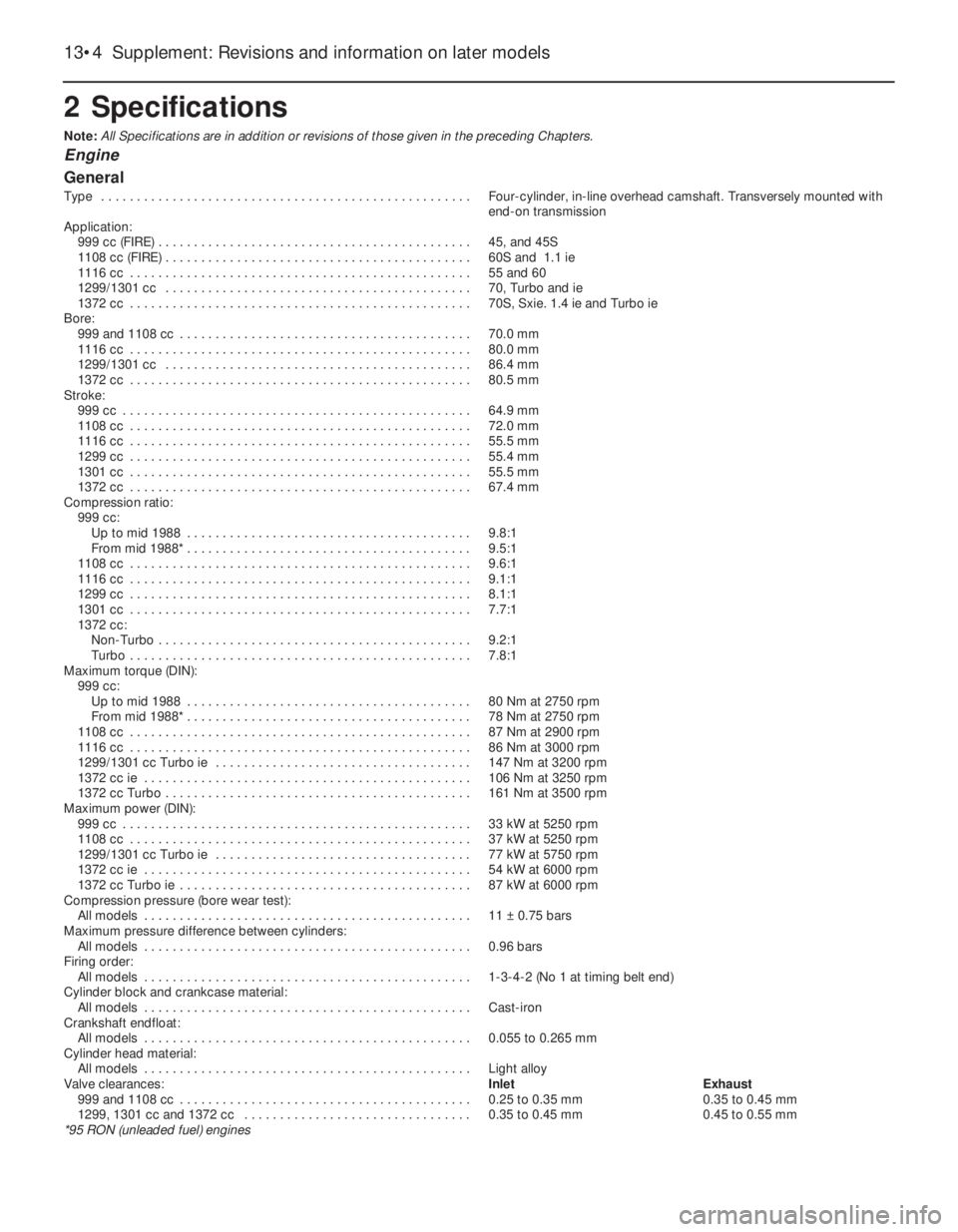
2 Specifications
Note: All Specifications are in addition or revisions of those given in the preceding Chapters.
Engine
General
Type . . . . . . . . . . . . . . . . . . . . . . . . . . . . . . . . . . . . . . . . . . . . . . . . . . . . Four-cylinder, in-line overhead camshaft. Transversely mounted with
end-on transmission
Application:
999 cc (FIRE) . . . . . . . . . . . . . . . . . . . . . . . . . . . . . . . . . . . . . . . . . . . . 45, and 45S
1108 cc (FIRE) . . . . . . . . . . . . . . . . . . . . . . . . . . . . . . . . . . . . . . . . . . . 60S and 1.1 ie
1116 cc . . . . . . . . . . . . . . . . . . . . . . . . . . . . . . . . . . . . . . . . . . . . . . . . 55 and 60
1299/1301 cc . . . . . . . . . . . . . . . . . . . . . . . . . . . . . . . . . . . . . . . . . . . 70, Turbo and ie
1372 cc . . . . . . . . . . . . . . . . . . . . . . . . . . . . . . . . . . . . . . . . . . . . . . . . 70S, Sxie. 1.4 ie and Turbo ie
Bore:
999 and 1108 cc . . . . . . . . . . . . . . . . . . . . . . . . . . . . . . . . . . . . . . . . . 70.0 mm
1116 cc . . . . . . . . . . . . . . . . . . . . . . . . . . . . . . . . . . . . . . . . . . . . . . . . 80.0 mm
1299/1301 cc . . . . . . . . . . . . . . . . . . . . . . . . . . . . . . . . . . . . . . . . . . . 86.4 mm
1372 cc . . . . . . . . . . . . . . . . . . . . . . . . . . . . . . . . . . . . . . . . . . . . . . . . 80.5 mm
Stroke:
999 cc . . . . . . . . . . . . . . . . . . . . . . . . . . . . . . . . . . . . . . . . . . . . . . . . . 64.9 mm
1108 cc . . . . . . . . . . . . . . . . . . . . . . . . . . . . . . . . . . . . . . . . . . . . . . . . 72.0 mm
1116 cc . . . . . . . . . . . . . . . . . . . . . . . . . . . . . . . . . . . . . . . . . . . . . . . . 55.5 mm
1299 cc . . . . . . . . . . . . . . . . . . . . . . . . . . . . . . . . . . . . . . . . . . . . . . . . 55.4 mm
1301 cc . . . . . . . . . . . . . . . . . . . . . . . . . . . . . . . . . . . . . . . . . . . . . . . . 55.5 mm
1372 cc . . . . . . . . . . . . . . . . . . . . . . . . . . . . . . . . . . . . . . . . . . . . . . . . 67.4 mm
Compression ratio:
999 cc:
Up to mid 1988 . . . . . . . . . . . . . . . . . . . . . . . . . . . . . . . . . . . . . . . . 9.8:1
From mid 1988* . . . . . . . . . . . . . . . . . . . . . . . . . . . . . . . . . . . . . . . . 9.5:1
1108 cc . . . . . . . . . . . . . . . . . . . . . . . . . . . . . . . . . . . . . . . . . . . . . . . . 9.6:1
1116 cc . . . . . . . . . . . . . . . . . . . . . . . . . . . . . . . . . . . . . . . . . . . . . . . . 9.1:1
1299 cc . . . . . . . . . . . . . . . . . . . . . . . . . . . . . . . . . . . . . . . . . . . . . . . . 8.1:1
1301 cc . . . . . . . . . . . . . . . . . . . . . . . . . . . . . . . . . . . . . . . . . . . . . . . . 7.7:1
1372 cc:
Non-Turbo . . . . . . . . . . . . . . . . . . . . . . . . . . . . . . . . . . . . . . . . . . . . 9.2:1
Turbo . . . . . . . . . . . . . . . . . . . . . . . . . . . . . . . . . . . . . . . . . . . . . . . . 7.8:1
Maximum torque (DIN):
999 cc:
Up to mid 1988 . . . . . . . . . . . . . . . . . . . . . . . . . . . . . . . . . . . . . . . . 80 Nm at 2750 rpm
From mid 1988* . . . . . . . . . . . . . . . . . . . . . . . . . . . . . . . . . . . . . . . . 78 Nm at 2750 rpm
1108 cc . . . . . . . . . . . . . . . . . . . . . . . . . . . . . . . . . . . . . . . . . . . . . . . . 87 Nm at 2900 rpm
1116 cc . . . . . . . . . . . . . . . . . . . . . . . . . . . . . . . . . . . . . . . . . . . . . . . . 86 Nm at 3000 rpm
1299/1301 cc Turbo ie . . . . . . . . . . . . . . . . . . . . . . . . . . . . . . . . . . . . 147 Nm at 3200 rpm
1372 cc ie . . . . . . . . . . . . . . . . . . . . . . . . . . . . . . . . . . . . . . . . . . . . . . 106 Nm at 3250 rpm
1372 cc Turbo . . . . . . . . . . . . . . . . . . . . . . . . . . . . . . . . . . . . . . . . . . . 161 Nm at 3500 rpm
Maximum power (DIN):
999 cc . . . . . . . . . . . . . . . . . . . . . . . . . . . . . . . . . . . . . . . . . . . . . . . . . 33 kW at 5250 rpm
1108 cc . . . . . . . . . . . . . . . . . . . . . . . . . . . . . . . . . . . . . . . . . . . . . . . . 37 kW at 5250 rpm
1299/1301 cc Turbo ie . . . . . . . . . . . . . . . . . . . . . . . . . . . . . . . . . . . . 77 kW at 5750 rpm
1372 cc ie . . . . . . . . . . . . . . . . . . . . . . . . . . . . . . . . . . . . . . . . . . . . . . 54 kW at 6000 rpm
1372 cc Turbo ie . . . . . . . . . . . . . . . . . . . . . . . . . . . . . . . . . . . . . . . . . 87 kW at 6000 rpm
Compression pressure (bore wear test):
All models . . . . . . . . . . . . . . . . . . . . . . . . . . . . . . . . . . . . . . . . . . . . . . 11 ± 0.75 bars
Maximum pressure difference between cylinders:
All models . . . . . . . . . . . . . . . . . . . . . . . . . . . . . . . . . . . . . . . . . . . . . . 0.96 bars
Firing order:
All models . . . . . . . . . . . . . . . . . . . . . . . . . . . . . . . . . . . . . . . . . . . . . . 1-3-4-2 (No 1 at timing belt end)
Cylinder block and crankcase material:
All models . . . . . . . . . . . . . . . . . . . . . . . . . . . . . . . . . . . . . . . . . . . . . . Cast-iron
Crankshaft endfloat:
All models . . . . . . . . . . . . . . . . . . . . . . . . . . . . . . . . . . . . . . . . . . . . . . 0.055 to 0.265 mm
Cylinder head material:
All models . . . . . . . . . . . . . . . . . . . . . . . . . . . . . . . . . . . . . . . . . . . . . . Light alloy
Valve clearances:Inlet Exhaust
999 and 1108 cc . . . . . . . . . . . . . . . . . . . . . . . . . . . . . . . . . . . . . . . . . 0.25 to 0.35 mm 0.35 to 0.45 mm
1299, 1301 cc and 1372 cc . . . . . . . . . . . . . . . . . . . . . . . . . . . . . . . . 0.35 to 0.45 mm 0.45 to 0.55 mm
*95 RON (unleaded fuel) engines
13•4 Supplement: Revisions and information on later models
Page 130 of 303
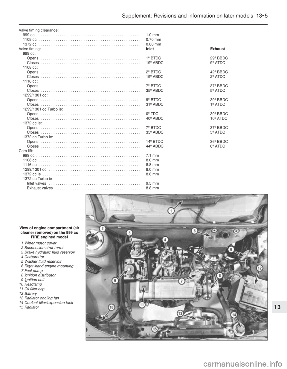
Valve timing clearance:
999 cc . . . . . . . . . . . . . . . . . . . . . . . . . . . . . . . . . . . . . . . . . . . . . . . . . 1.0 mm
1108 cc . . . . . . . . . . . . . . . . . . . . . . . . . . . . . . . . . . . . . . . . . . . . . . . . 0.70 mm
1372 cc . . . . . . . . . . . . . . . . . . . . . . . . . . . . . . . . . . . . . . . . . . . . . . . . 0.80 mm
Valve timing:Inlet Exhaust
999 cc:
Opens . . . . . . . . . . . . . . . . . . . . . . . . . . . . . . . . . . . . . . . . . . . . . . . 1º BTDC 29º BBDC
Closes . . . . . . . . . . . . . . . . . . . . . . . . . . . . . . . . . . . . . . . . . . . . . . . 19º ABDC 9º ATDC
1108 cc:
Opens . . . . . . . . . . . . . . . . . . . . . . . . . . . . . . . . . . . . . . . . . . . . . . . 2º BTDC 42º BBDC
Closes . . . . . . . . . . . . . . . . . . . . . . . . . . . . . . . . . . . . . . . . . . . . . . . 19º ABDC 2º ATDC
1116 cc:
Opens . . . . . . . . . . . . . . . . . . . . . . . . . . . . . . . . . . . . . . . . . . . . . . . 7º BTDC 37º BBDC
Closes . . . . . . . . . . . . . . . . . . . . . . . . . . . . . . . . . . . . . . . . . . . . . . . 35º ABDC 5º ATDC
1299/1301 cc:
Opens . . . . . . . . . . . . . . . . . . . . . . . . . . . . . . . . . . . . . . . . . . . . . . . 9º BTDC 39º BBDC
Closes . . . . . . . . . . . . . . . . . . . . . . . . . . . . . . . . . . . . . . . . . . . . . . . 31º ABDC 1º ATDC
1299/1301 cc Turbo ie:
Opens . . . . . . . . . . . . . . . . . . . . . . . . . . . . . . . . . . . . . . . . . . . . . . . 0º TDC 30º BBDC
Closes . . . . . . . . . . . . . . . . . . . . . . . . . . . . . . . . . . . . . . . . . . . . . . . 40º ABDC 10º ATDC
1372 cc ie:
Opens . . . . . . . . . . . . . . . . . . . . . . . . . . . . . . . . . . . . . . . . . . . . . . . 7º BTDC 37º BBDC
Closes . . . . . . . . . . . . . . . . . . . . . . . . . . . . . . . . . . . . . . . . . . . . . . . 35º ABDC 5º ATDC
1372 cc Turbo ie:
Opens . . . . . . . . . . . . . . . . . . . . . . . . . . . . . . . . . . . . . . . . . . . . . . . 14º BTDC 36º BBDC
Closes . . . . . . . . . . . . . . . . . . . . . . . . . . . . . . . . . . . . . . . . . . . . . . . 44º ABDC 6º ATDC
Cam lift:
999 cc . . . . . . . . . . . . . . . . . . . . . . . . . . . . . . . . . . . . . . . . . . . . . . . . . 7.1 mm
1108 cc . . . . . . . . . . . . . . . . . . . . . . . . . . . . . . . . . . . . . . . . . . . . . . . . 8.0 mm
1116 cc . . . . . . . . . . . . . . . . . . . . . . . . . . . . . . . . . . . . . . . . . . . . . . . . 8.8 mm
1299/1301 cc . . . . . . . . . . . . . . . . . . . . . . . . . . . . . . . . . . . . . . . . . . . 8.0 mm
1372 cc ie . . . . . . . . . . . . . . . . . . . . . . . . . . . . . . . . . . . . . . . . . . . . . . 8.8 mm
1372 cc Turbo ie
Inlet valves . . . . . . . . . . . . . . . . . . . . . . . . . . . . . . . . . . . . . . . . . . . 9.5 mm
Exhaust valves . . . . . . . . . . . . . . . . . . . . . . . . . . . . . . . . . . . . . . . . 8.8 mm
Supplement: Revisions and information on later models 13•5
13
View of engine compartment (air
cleaner removed) on the 999 cc
FIRE engined model
1 Wiper motor cover
2 Suspension strut turret
3 Brake hydraulic fluid reservoir
4 Carburettor
5 Washer fluid reservoir
6 Right-hand engine mounting
7 Fuel pump
8 Ignition distributor
9 Ignition coil
10 Headlamp
11 Oil filler cap
12 Battery
13 Radiator cooling fan
14 Coolant filler/expansion tank
15 Radiator