FIAT UNO 1983 Service Repair Manual
Manufacturer: FIAT, Model Year: 1983, Model line: UNO, Model: FIAT UNO 1983Pages: 303, PDF Size: 10.36 MB
Page 231 of 303
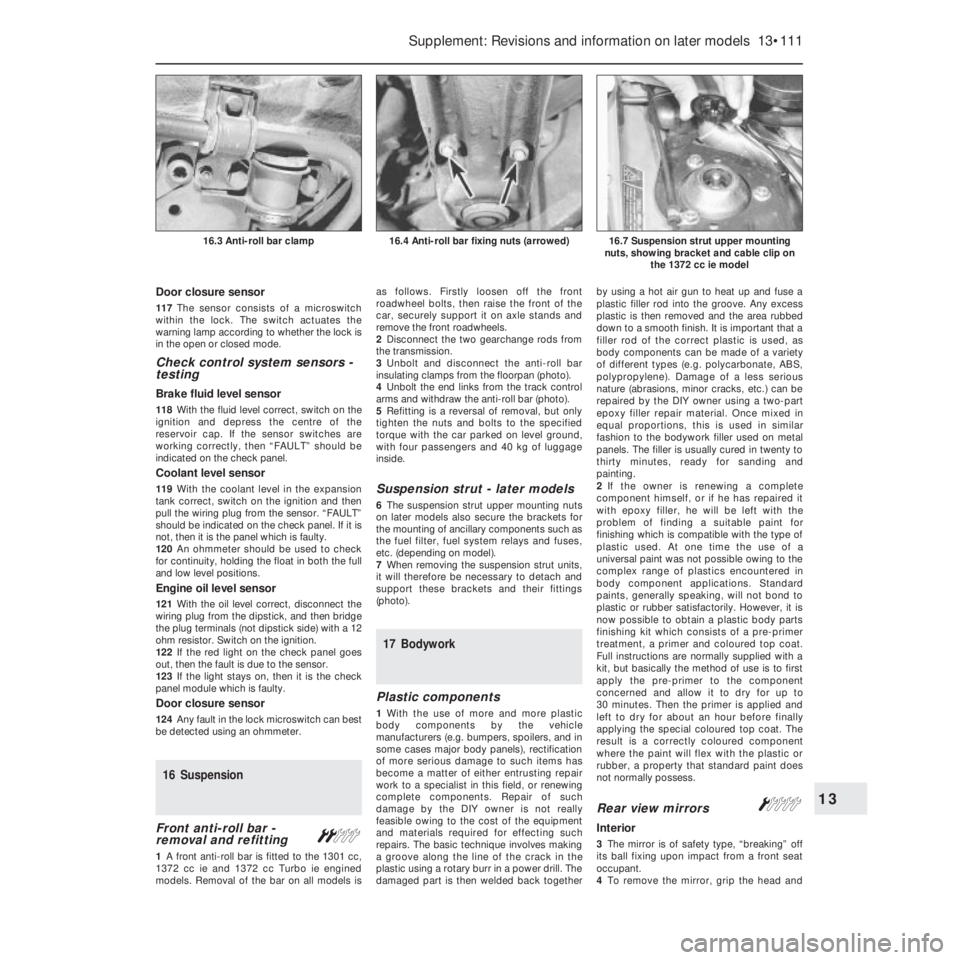
adjustment procedures are the same as those
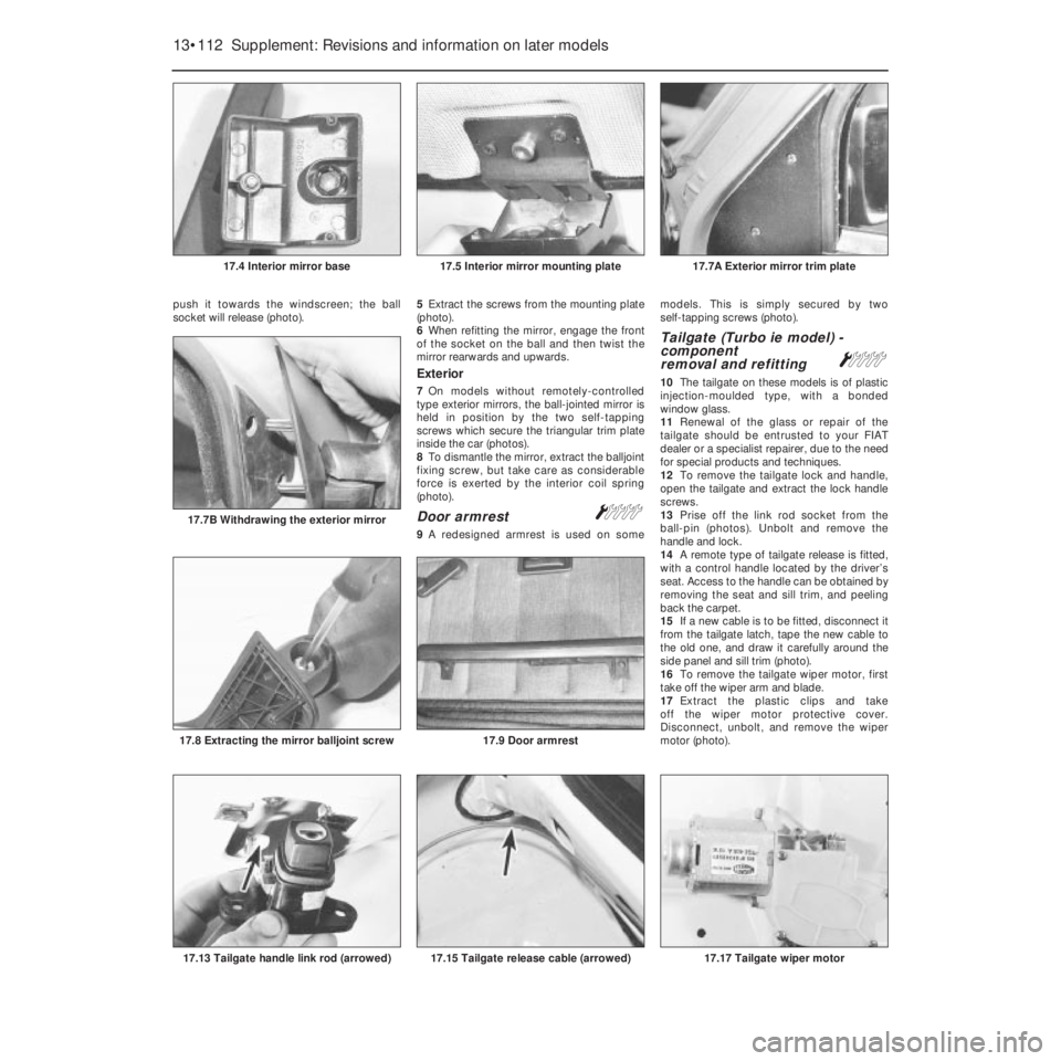
outlined for the previous model units in
Chapter 9, but ensure that the load
compensation lever is turned to the “O”
(normal load setting) position before making
any adjustments.
Headlamp unit removal - later
models
32The removal and refitting procedures
described in Chapter 9 also apply to the later
headlamp type, but note that later units are
secured in position by three retaining screws.
Headlamp dim-dip system -
description
33On later models, the wiring circuit has
been modified to prevent the car being drivenon parking lamps only in built-up areas.
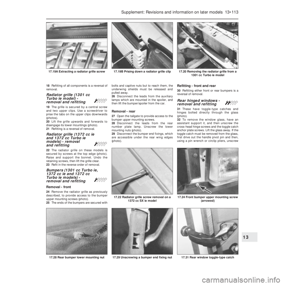
34Headlamp intensity is reduced by the
transformer located at the front of the engine
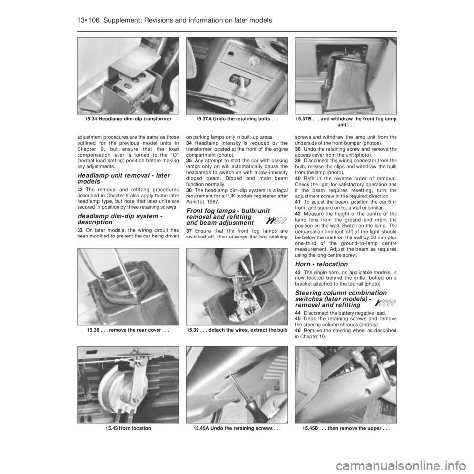
compartment (photo).
35Any attempt to start the car with parking
lamps only on will automatically cause the
headlamps to switch on with a low-intensity
dipped beam. Dipped and main beam
function normally.
36The headlamp dim-dip system is a legal
requirement for all UK models registered after
April 1st, 1987.
Front fog lamps - bulb/unit
removal and refitting
and beam adjustment
ª
37Ensure that the front fog lamps are
switched off, then unscrew the two retainingscrews and withdraw the lamp unit from the
underside of the front bumper (photos).
38Undo the retaining screw and remove the
access cover from the unit (photo).
39Disconnect the wiring connector from the
bulb, release the clips and withdraw the bulb
from the lamp (photo).
40Refit in the reverse order of removal.
Check the light for satisfactory operation and
if the beam requires resetting, turn the
adjustment screw in the required direction.
41To adjust the beam, position the car 5 m
from, and square on to, a wall or similar.
42Measure the height of the centre of the
lamp lens from the ground and mark the
position on the wall. Switch on the lamp. The
demarcation line (cut-off) of the light should
be below the mark on the wall by 50 mm plus
one-third of the ground-to-lamp centre
measurement. Adjust the beam as required
using the long centre screw.
Horn - relocation
43The single horn, on applicable models, is
now located behind the grille, bolted on a
bracket attached to the top rail (photo).
Steering column combination
switches (later models) -
removal and refitting
Á
44Disconnect the battery negative lead.
45Undo the retaining screws and remove
the steering column shrouds (photos).
46Remove the steering wheel as described
in Chapter 10.
13•106 Supplement: Revisions and information on later models
15.45B . . . then remove the upper . . .15.45A Undo the retaining screws . . .15.43 Horn location
15.39 . . . detach the wires, extract the bulb15.38 . . . remove the rear cover . . .
15.37B . . . and withdraw the front fog lamp
unit . . .15.37A Undo the retaining bolts . . .15.34 Headlamp dim-dip transformer
Page 232 of 303
47Loosen off the switch-to-column clamp
screw, disconnect the wiring connectors to
the switch and withdraw the switch from the
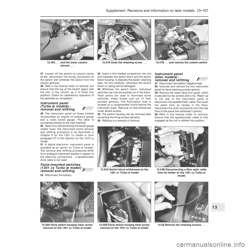
column (photos).
48Refit in the reverse order of removal, but
ensure that the lug of the switch aligns with
the slot in the column as it is fitted into
position. Check for satisfactory operation of
the switches on completion.
Instrument panel
(Turbo ie models) -
removal and refitting
Á
49The instrument panel on these models
incorporates an engine oil pressure gauge
and a turbo boost gauge. The latter is
connected directly to the inlet manifold.
50Apart from disconnecting the boost gauge
rubber hose, the instrument panel removal
and refitting procedure is as described in
Chapter 9 for the 1301 cc model or from
paragraph 57 in this Section for the 1372 cc
model.
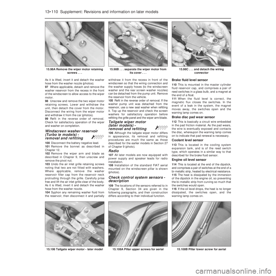
51A digital electronic instrument panel is
available as an option on Turbo ie models.
The removal and refitting procedures differ
from analogue instrument panels in respect of
the electrical connections - a speedometer
drive cable is not used.
Facia-mounted switches
(1301 cc Turbo ie model) -
removal and refitting
Á
52Disconnect the battery.53Insert a thin-bladed screwdriver into the
joint between the switch block and the switch
block housing, to depress the plastic retaining
tabs. Do this carefully, otherwise the switch
block or casing will be damaged.
54Withdraw the switch block. Individual
switches can now be pushed out of the block.
Fibre optics are used to illuminate some
switches, these simply pull out of their
sockets (photos). The illumination bulb is
located on a crossmember found behind the
instrument pack. Removal of instruments/top
cover allows access.
55The switch housing can be removed after
extracting the fixing screws (photos).
56Refitting is a reversal of removal.
Instrument panel
(later models) -
removal and refitting
Á57Disconnect the battery negative lead.
58Unscrew and remove the two instrument
panel-to-facia retaining screws (photo).
59Remove the lower facia trim panel, which
is secured by two screws and a nut. Reach up
to the rear of the instrument panel to
disconnect the speedometer cable, then push
the panel from its recess in the facia.
Disconnect the multi-connectors from the rear
face of the panel and withdraw it (photo).
60Refit in the reverse order of removal.
Ensure that the speedometer cable is fully
engaged as the unit is refitted into position.
Supplement: Revisions and information on later models 13•107
15.47B . . . and remove the column switch15.47A Undo the retaining screw . . .15.45C . . . and the lower column
shroud . . .
15.58 Remove the retaining screws . . .15.55B Facia switch housing inner screw
removal on the 1031 cc Turbo ie model
15.54B Disconnecting a fibre optic cable
from its holder on the 1301 cc Turbo ie
model15.54A Switch block withdrawal on the
1301 cc Turbo ie model
15.55A Facia switch housing lower screw
removal on the 1301 cc Turbo ie model
13
Page 233 of 303
Auxiliary control panel
(later models) -
removal and refitting
Á
61Disconnect the battery negative lead.
62Insert the flat of a screwdriver under the
trim piece at the end of the auxiliary panel as
shown and prise it free. Repeat the procedure
and remove the trim piece at the other end of
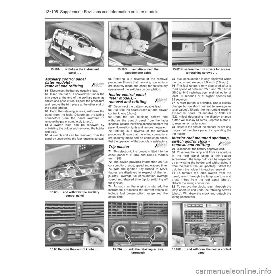
the panel (photo).
63Undo the retaining screws, withdraw the
panel from the facia. Disconnect the wiring
connectors from the panel switches to
remove the panel completely (photo).
64A switch bulb can be renewed by
untwisting the holder and removing the holder
and bulb.
65A switch unit can be removed from the
panel by unscrewing the four retaining screws.66Refitting is a reversal of the removal
procedure. Ensure that the wiring connections
are securely made and check for satisfactory
operation of the switches on completion.
Heater control panel
(later models) -
removal and refitting
Á
67Disconnect the battery negative lead.
68Pull free the heater/fresh air and blower
control knobs (photo).
69Undo the two retaining screws and
withdraw the control panel from the facia
(photos). Detach the wiring connectors from the
panel illumination lights and remove the panel.
70Refitting is a reversal of the removal
procedure. Ensure that the wiring connections
are securely made and on completion check
that the operation of the controls is satisfactory.
Trip master Á
71This electronic instrument is fitted into the
check panel of 1100SL and 1300SL models
from 1986.
72The device provides information on fuel
consumption, range, speed and elapsed time.
73With the ignition key turned to MAR,
figures are displayed in respect of the last
journey - average fuel consumption, average
speed and elapsed time (up to switching off
the ignition).
74As soon as the engine is started, the
instrument processes the current values to
include fuel consumption, range and the
actual time. 75Fuel consumption is only displayed when
the road speed exceeds 8.0 km/h (5.0 mph).
76The fuel range is only displayed after a
road speed of between 25.0 and 70.0 km/h
(15.0 to 44.0 mph) has been maintained for at
least 90 seconds or at higher speeds for
22 seconds.
77A reset button is provided, also a display
change button (from instant to average or
total values). Should the instrument reading
exceed 99 hours, 59 minutes or 1000 km
(622 miles) depressing the display change
button will display all zeros. Depress button E
to resume normal function.
78Refer to the end of the manual for a wiring
diagram of the check panel, incorporating the
trip master.
Interior roof mounted spotlamp,
switch and/or clock -
removal and refitting
Á
79Disconnect the battery negative lead.
80Prise free the lamp unit from its aperture
in the roof panel using a thin-bladed
screwdriver. The lamp bulb can be inspected
by untwisting the holder and withdrawing it
from the rear of the unit (photos). Extract the
bulb from the holder if it requires renewal.
81To remove the lamp switch from the
panel, reach through the lamp aperture and
press it free from the roof panel (photo).
Detach the wiring connectors.
82To remove the clock, reach through the
lamp aperture and undo the retaining screws
(photo). Withdraw the clock and detach the
wiring connectors.
13•108 Supplement: Revisions and information on later models
15.69B . . . and withdraw the heater control
panel15.69A . . . undo the retaining screws
(arrowed)15.68 Remove the control knobs . . .
15.63 . . . and withdraw the auxiliary
control panel
15.62 Prise free the trim covers for access
to retaining screws . . .15.59B . . . and disconnect the
speedometer cable15.59A . . . withdraw the instrument
panel . . .
Page 234 of 303
83Refitting is a reversal of the removal
procedure. Reset the clock on completion.
Central door locking system
84Certain later models, equipped with a
central door locking system, have an infra-red
remote control for opening the door locks.
85It is important that the battery used in the
hand control is renewed when necessary with
one of identical type (Duracell 7H34). This is
only available as a FIAT spare part (No
7595393).
86The remote control door lock receiver unit
can be removed by carefully prising it free
from the roof panel and disconnecting the
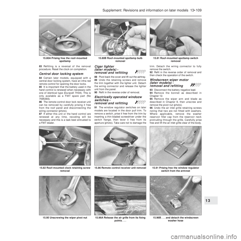
wiring connector (photo).
87If either this unit or the hand control are
renewed at any time, recoding will be
necessary and this is a task best entrusted to
a FIAT dealer.
Cigar lighter
(later models) -
removal and refitting
Á
88Pivot back the cover and lift out the ashtray.
89Undo the retaining screws and remove
the trim together with the lighter unit. Detach
the wiring connector and release the lighter
unit from the panel.
90Refit in the reverse order of removal.
Electrically operated windozw
switches -
removal and refitting
Á
91The window regulator switches on later
models are located in the door pull trim. To
remove a switch, prise it free from the trim by
inserting a thin-bladed screwdriver under the
switch flange, then lever it free from its
aperture (photo). Take care not to damage thetrim. Detach the wiring connector to fully
remove the switch.
92Refit in the reverse order of removal and
then check the operation of the switch.
Windscreen wiper motor
(later models) -
removal and refitting
ª
93Disconnect the battery negative lead.
94Remove the bonnet as described in
Chapter 12.
95Remove the wiper arm and blade as
described in Chapter 9, then unscrew and
remove the pivot nut (photo).
96Undo the air inlet grille retaining screws
noting that two are not fitted with washers.
Where applicable, remove the washer
reservoir filler cap from the reservoir neck
protruding through the grille. Carefully prise
free and lift the air inlet grille clear of the body.
Supplement: Revisions and information on later models 13•109
15.81 Roof-mounted spotlamp switch
removal15.80B Roof-mounted spotlamp bulb
removal15.80A Prising free the roof-mounted
spotlamp
15.96B . . . and detach the windscreen
washer hose15.96A Release the air grille from its fixing
points . . .15.95 Unscrewing the wiper pivot nut
15.91 Prising free the window regulator
switch from the armrest15.86 Remote control receiver unit removal15.82 Roof-mounted clock retaining screw
removal
13
Page 235 of 303
As it is lifted, invert it and detach the washer
hose from the washer nozzle (photos).
97Where applicable, detach and remove the
washer reservoir from the recess in the front
of the windscreen to allow access to the wiper
motor.
98Unscrew and remove the two wiper motor
retaining screws. Lower and withdraw the
unit, then detach the cover from the motor.
Disconnect the wiring from the wiper motor
and withdraw it from the car (photos).
99Refit in the reverse order of removal.
Check for satisfactory operation of the wiper
and washer on completion.
Windscreen washer reservoir
(Turbo ie models) -
removal and refitting
Á
100Disconnect the battery negative lead.
101Remove the bonnet as described in
Chapter 12.
102Remove the wiper arm and blade as
described in Chapter 9, then unscrew and
remove the pivot nut.
103Undo the air inlet grille retaining screws
noting that two are not fitted with washers.
Where applicable, remove the washer
reservoir filler cap from the reservoir neck
protruding through the grille. Carefully prise
free and lift the air inlet grille clear of the body.
As it is lifted, invert it and detach the washer
hose from the washer nozzle.
104Syphon any remaining washer fluid from
the reservoir, then disconnect it and partiallywithdraw it from the recess in front of the
windscreen so that the wiring connection and
the washer supply hoses (to the windscreen
washer and the rear screen washer nozzles)
can be detached from the pump unit. Remove
the reservoir from the vehicle.
105Refit in the reverse order of removal. If the
washer pump unit was detached from the
reservoir, use a new seal washer when refitting
it. Top up the reservoir and check the screen
washers for satisfactory operation before
refitting the grille panel and the wiper arm/blade.
Tailgate wiper motor
(later models) -
removal and refitting
Á
106Although the tailgate wiper motor differs
in appearance, its removal and refitting
procedures are much the same as those
described for the earlier models in Section 27
of Chapter 9 (photo).
Radio
107All later models are now equipped with
power supply and speaker leads for radio
installation.
108Installation of the standard FIAT aerial
mounted on the windscreen pillar is shown
(photos).
Check control system sensors -
description
109The locations of the sensors referred to in
Chapter 9, Section 34 are given in the
following paragraphs, and their construction
differs according to their individual function.
Brake fluid level sensor
110This is mounted in the master cylinder
fluid reservoir cap, and comprises a pair of
reed switches in a glass bulb, and a magnet at
the end of a float.
111When the fluid level is correct, the
magnetic flux closes the switches. In the
event of a leak in the system, the magnet
moves away, the switches open and the
warning lamp comes on.
Brake disc pad wear sensor
112This is basically a circuit wire embedded
in the pad friction material. As the pad wears,
the wire is eventually exposed and contacts
the disc, whereupon the warning lamp comes
on to indicate that pad renewal is necessary.
Coolant level sensor
113This is located in the cooling system
expansion tank, and is of the reed switch
type, which operates in a similar way to that
described for the brake fluid sensor.
Engine oil level sensor
114This is located at the end of the dipstick,
and comprises a pair of switches at the end of a
bi-metallic strip, heated by electrical resistance.
115The heat is dissipated by the immersion
of the dipstick in the engine oil, so preventing
the bi-metallic strip from curving so much that
the switches would open.
116If the oil level drops, the heat is no longer
dissipated, the switches open, and the
warning lamp comes on.
13•110 Supplement: Revisions and information on later models
15.108B Pillar lower screw for aerial15.108A Pillar upper screws for aerial15.106 Tailgate wiper motor - later model
15.98C . . . and detach the wiring
connector15.98B . . . separate the wiper motor from
its cover . . .15.98A Remove the wiper motor retaining
screws . . .
Page 236 of 303
Door closure sensor
117The sensor consists of a microswitch
within the lock. The switch actuates the
warning lamp according to whether the lock is
in the open or closed mode.
Check control system sensors -
testing
Brake fluid level sensor
118With the fluid level correct, switch on the
ignition and depress the centre of the
reservoir cap. If the sensor switches are
working correctly, then “FAULT” should be
indicated on the check panel.
Coolant level sensor
119With the coolant level in the expansion
tank correct, switch on the ignition and then
pull the wiring plug from the sensor. “FAULT”
should be indicated on the check panel. If it is
not, then it is the panel which is faulty.
120An ohmmeter should be used to check
for continuity, holding the float in both the full
and low level positions.
Engine oil level sensor
121With the oil level correct, disconnect the
wiring plug from the dipstick, and then bridge
the plug terminals (not dipstick side) with a 12
ohm resistor. Switch on the ignition.
122If the red light on the check panel goes
out, then the fault is due to the sensor.
123If the light stays on, then it is the check
panel module which is faulty.
Door closure sensor
124Any fault in the lock microswitch can best
be detected using an ohmmeter.
16 Suspension
Front anti-roll bar -
removal and refittingª
1A front anti-roll bar is fitted to the 1301 cc,
1372 cc ie and 1372 cc Turbo ie engined
models. Removal of the bar on all models isas follows. Firstly loosen off the front
roadwheel bolts, then raise the front of the
car, securely support it on axle stands and
remove the front roadwheels.
2Disconnect the two gearchange rods from
the transmission.
3Unbolt and disconnect the anti-roll bar
insulating clamps from the floorpan (photo).
4Unbolt the end links from the track control
arms and withdraw the anti-roll bar (photo).
5Refitting is a reversal of removal, but only
tighten the nuts and bolts to the specified
torque with the car parked on level ground,
with four passengers and 40 kg of luggage
inside.
Suspension strut - later models
6The suspension strut upper mounting nuts
on later models also secure the brackets for
the mounting of ancillary components such as
the fuel filter, fuel system relays and fuses,
etc. (depending on model).
7When removing the suspension strut units,
it will therefore be necessary to detach and
support these brackets and their fittings
(photo).
17 Bodywork
Plastic components
1With the use of more and more plastic
body components by the vehicle
manufacturers (e.g. bumpers, spoilers, and in
some cases major body panels), rectification
of more serious damage to such items has
become a matter of either entrusting repair
work to a specialist in this field, or renewing
complete components. Repair of such
damage by the DIY owner is not really
feasible owing to the cost of the equipment
and materials required for effecting such
repairs. The basic technique involves making
a groove along the line of the crack in the
plastic using a rotary burr in a power drill. The
damaged part is then welded back togetherby using a hot air gun to heat up and fuse a
plastic filler rod into the groove. Any excess
plastic is then removed and the area rubbed
down to a smooth finish. It is important that a
filler rod of the correct plastic is used, as
body components can be made of a variety
of different types (e.g. polycarbonate, ABS,
polypropylene). Damage of a less serious
nature (abrasions, minor cracks, etc.) can be
repaired by the DIY owner using a two-part
epoxy filler repair material. Once mixed in
equal proportions, this is used in similar
fashion to the bodywork filler used on metal
panels. The filler is usually cured in twenty to
thirty minutes, ready for sanding and
painting.
2If the owner is renewing a complete
component himself, or if he has repaired it
with epoxy filler, he will be left with the
problem of finding a suitable paint for
finishing which is compatible with the type of
plastic used. At one time the use of a
universal paint was not possible owing to the
complex range of plastics encountered in
body component applications. Standard
paints, generally speaking, will not bond to
plastic or rubber satisfactorily. However, it is
now possible to obtain a plastic body parts
finishing kit which consists of a pre-primer
treatment, a primer and coloured top coat.
Full instructions are normally supplied with a
kit, but basically the method of use is to first
apply the pre-primer to the component
concerned and allow it to dry for up to
30 minutes. Then the primer is applied and
left to dry for about an hour before finally
applying the special coloured top coat. The
result is a correctly coloured component
where the paint will flex with the plastic or
rubber, a property that standard paint does
not normally possess.
Rear view mirrors Á
Interior
3The mirror is of safety type, “breaking” off
its ball fixing upon impact from a front seat
occupant.
4To remove the mirror, grip the head and
Supplement: Revisions and information on later models 13•111
16.7 Suspension strut upper mounting
nuts, showing bracket and cable clip on
the 1372 cc ie model16.4 Anti-roll bar fixing nuts (arrowed)16.3 Anti-roll bar clamp
13
Page 237 of 303
push it towards the windscreen; the ball
socket will release (photo).5Extract the screws from the mounting plate
(photo).
6When refitting the mirror, engage the front
of the socket on the ball and then twist the
mirror rearwards and upwards.
Exterior
7On models without remotely-controlled
type exterior mirrors, the ball-jointed mirror is
held in position by the two self-tapping
screws which secure the triangular trim plate
inside the car (photos).
8To dismantle the mirror, extract the balljoint
fixing screw, but take care as considerable
force is exerted by the interior coil spring
(photo).
Door armrestÁ
9A redesigned armrest is used on somemodels. This is simply secured by two
self-tapping screws (photo).
Tailgate (Turbo ie model) -
component
removal and refitting
Á
10The tailgate on these models is of plastic
injection-moulded type, with a bonded
window glass.
11Renewal of the glass or repair of the
tailgate should be entrusted to your FIAT
dealer or a specialist repairer, due to the need
for special products and techniques.
12To remove the tailgate lock and handle,
open the tailgate and extract the lock handle
screws.
13Prise off the link rod socket from the
ball-pin (photos). Unbolt and remove the
handle and lock.
14A remote type of tailgate release is fitted,
with a control handle located by the driver’s
seat. Access to the handle can be obtained by
removing the seat and sill trim, and peeling
back the carpet.
15If a new cable is to be fitted, disconnect it
from the tailgate latch, tape the new cable to
the old one, and draw it carefully around the
side panel and sill trim (photo).
16To remove the tailgate wiper motor, first
take off the wiper arm and blade.
17Extract the plastic clips and take
off the wiper motor protective cover.
Disconnect, unbolt, and remove the wiper
motor (photo).
13•112 Supplement: Revisions and information on later models
17.17 Tailgate wiper motor17.15 Tailgate release cable (arrowed)17.13 Tailgate handle link rod (arrowed)
17.9 Door armrest17.8 Extracting the mirror balljoint screw
17.7B Withdrawing the exterior mirror
17.7A Exterior mirror trim plate17.5 Interior mirror mounting plate17.4 Interior mirror base
Page 238 of 303
18Refitting of all components is a reversal of
removal.
Radiator grille (1301 cc
Turbo ie model) -
removal and refitting
Á
19The grille is secured by a central screw
and two upper clips. Use a screwdriver to
prise the tabs on the upper clips downwards
(photos).
20Lift the grille upwards and forwards to
disengage its lower mountings (photo).
21Refitting is a reversal of removal.
Radiator grille (1372 cc ie
and 1372 cc Turbo ie
models) - removal
and refitting
Á
22The radiator grille on these models is
secured by screws at the top edge (photo).
Raise and support the bonnet. Undo the
retaining screws, then lift the grille clear.
23Refit in the reverse order of removal.
Bumpers (1301 cc Turbo ie,
1372 cc ie and 1372 cc
Turbo ie models) -
removal and refitting
Á
Removal - front
24Remove the radiator grille as previously
described, to provide access to the bumper
upper mounting screws (photo).
25The ends of the bumpers are secured withbolts and captive nuts but to reach them, the
underwing shields must be released and
pulled away.
26Disconnect the leads from the auxiliary
lamps which are mounted in the spoiler, and
then lift the bumper/spoiler from the car.
Removal - rear
27Open the tailgate to provide access to the
bumper upper mounting screws.
28Disconnect the leads from the rear
number plate lamp. Unscrew the lower
mounting nuts (photo).
29Disconnect the bumper end fixings, which
are accessible under the rear wing edges
(photo).
Refitting - front and rear
30Refitting either front or rear bumpers is a
reversal of removal.
Rear hinged windows -
removal and refittingª
31These have toggle-type catches and
hinges bolted directly through the glass
(photo).
32To remove the window glass, have an
assistant support it, and then unscrew the
cross-head hinge screws and the toggle catch
anchor plate screws. Lift the glass away. If the
toggle catch must be removed from the glass,
first drive out the handle pivot pin and then,
using a pin wrench or circlip pliers, unscrew
Supplement: Revisions and information on later models 13•113
17.20 Removing the radiator grille from a
1301 cc Turbo ie model17.19B Prising down a radiator grille clip17.19A Extracting a radiator grille screw
17.31 Rear window toggle-type catch17.29 Unscrewing a bumper end fixing nut
17.24 Front bumper upper mounting screw
(arrowed)17.22 Radiator grille screw removal on a
1372 cc SX ie model
17.28 Rear bumper lower mounting nut
13
Page 239 of 303
the ring nut which secures the handle to the
glass.
33When refitting the screws or ring nut to
the glass, make sure that the insulating
washers are in good condition to prevent
metal-to-glass contact.Door trim panel
(Turbo ie model) -
removal and refitting
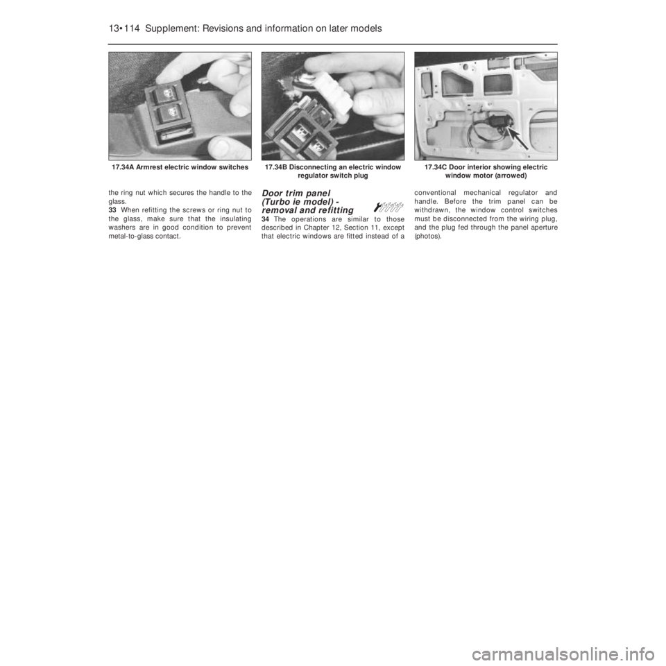
Á34The operations are similar to those
described in Chapter 12, Section 11, except
that electric windows are fitted instead of aconventional mechanical regulator and
handle. Before the trim panel can be
withdrawn, the window control switches
must be disconnected from the wiring plug,
and the plug fed through the panel aperture
(photos).
13•114 Supplement: Revisions and information on later models
17.34C Door interior showing electric
window motor (arrowed)17.34B Disconnecting an electric window
regulator switch plug17.34A Armrest electric window switches
Page 240 of 303
Wiring diagrams 14•1
14
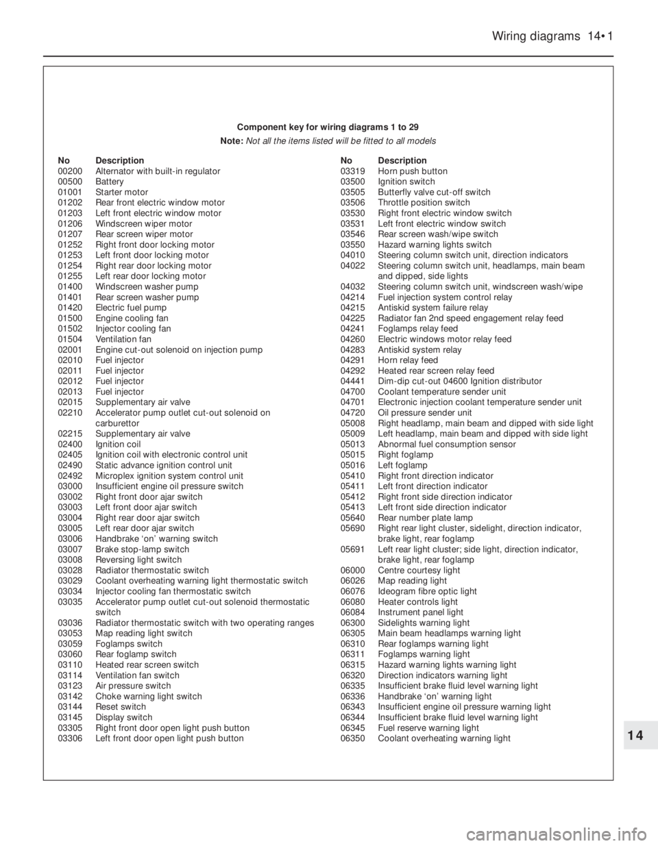
Component key for wiring diagrams 1 to 29
Note: Not all the items listed will be fitted to all models
No Description
00200 Alternator with built-in regulator
00500 Battery
01001 Starter motor
01202 Rear front electric window motor
01203 Left front electric window motor
01206 Windscreen wiper motor
01207 Rear screen wiper motor
01252 Right front door locking motor
01253 Left front door locking motor
01254 Right rear door locking motor
01255 Left rear door locking motor
01400 Windscreen washer pump
01401 Rear screen washer pump
01420 Electric fuel pump
01500 Engine cooling fan
01502 Injector cooling fan
01504 Ventilation fan
02001 Engine cut-out solenoid on injection pump
02010 Fuel injector
02011 Fuel injector
02012 Fuel injector
02013 Fuel injector
02015 Supplementary air valve
02210 Accelerator pump outlet cut-out solenoid on
carburettor
02215 Supplementary air valve
02400 Ignition coil
02405 Ignition coil with electronic control unit
02490 Static advance ignition control unit
02492 Microplex ignition system control unit
03000 Insufficient engine oil pressure switch
03002 Right front door ajar switch
03003 Left front door ajar switch
03004 Right rear door ajar switch
03005 Left rear door ajar switch
03006 Handbrake ‘on’ warning switch
03007 Brake stop-lamp switch
03008 Reversing light switch
03028 Radiator thermostatic switch
03029 Coolant overheating warning light thermostatic switch
03034 Injector cooling fan thermostatic switch
03035 Accelerator pump outlet cut-out solenoid thermostatic
switch
03036 Radiator thermostatic switch with two operating ranges
03053 Map reading light switch
03059 Foglamps switch
03060 Rear foglamp switch
03110 Heated rear screen switch
03114 Ventilation fan switch
03123 Air pressure switch
03142 Choke warning light switch
03144 Reset switch
03145 Display switch
03305 Right front door open light push button
03306 Left front door open light push button No Description
03319 Horn push button
03500 Ignition switch
03505 Butterfly valve cut-off switch
03506 Throttle position switch
03530 Right front electric window switch
03531 Left front electric window switch
03546 Rear screen wash/wipe switch
03550 Hazard warning lights switch
04010 Steering column switch unit, direction indicators
04022 Steering column switch unit, headlamps, main beam
and dipped, side lights
04032 Steering column switch unit, windscreen wash/wipe
04214 Fuel injection system control relay
04215 Antiskid system failure relay
04225 Radiator fan 2nd speed engagement relay feed
04241 Foglamps relay feed
04260 Electric windows motor relay feed
04283 Antiskid system relay
04291 Horn relay feed
04292 Heated rear screen relay feed
04441 Dim-dip cut-out 04600 Ignition distributor
04700 Coolant temperature sender unit
04701 Electronic injection coolant temperature sender unit
04720 Oil pressure sender unit
05008 Right headlamp, main beam and dipped with side light
05009 Left headlamp, main beam and dipped with side light
05013 Abnormal fuel consumption sensor
05015 Right foglamp
05016 Left foglamp
05410 Right front direction indicator
05411 Left front direction indicator
05412 Right front side direction indicator
05413 Left front side direction indicator
05640 Rear number plate lamp
05690 Right rear light cluster, sidelight, direction indicator,
brake light, rear foglamp
05691 Left rear light cluster; side light, direction indicator,
brake light, rear foglamp
06000 Centre courtesy light
06026 Map reading light
06076 Ideogram fibre optic light
06080 Heater controls light
06084 Instrument panel light
06300 Sidelights warning light
06305 Main beam headlamps warning light
06310 Rear foglamps warning light
06311 Foglamps warning light
06315 Hazard warning lights warning light
06320 Direction indicators warning light
06335 Insufficient brake fluid level warning light
06336 Handbrake ‘on’ warning light
06343 Insufficient engine oil pressure warning light
06344 Insufficient brake fluid level warning light
06345 Fuel reserve warning light
06350 Coolant overheating warning light