FORD CAPRI 1974 Workshop Manual
Manufacturer: FORD, Model Year: 1974, Model line: CAPRI, Model: FORD CAPRI 1974Pages: 205, PDF Size: 43.75 MB
Page 161 of 205
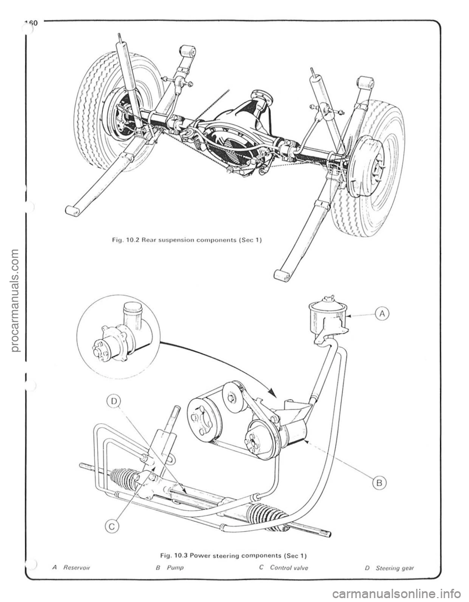
FiU.10.2 Rear Stlspcnsion componen!s (Sec 1 )
- 0
@
FlU. 10 .3 Power s toering comlJonerHS (Sec 1)
A Rcscrvo" 8 Pump C COII/rol valve o Sleelillg gear
procarmanuals.com
Page 162 of 205
Chapter 10 Suspension and steering 161
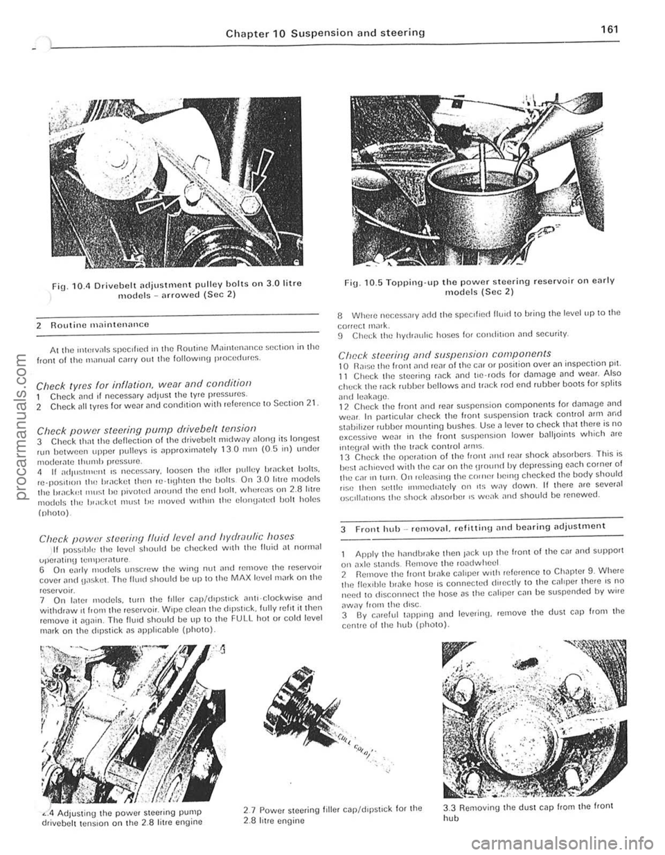
fig. 10.11 Drivebelt [ldjustlllent pulley holts on 3.0 litre models -arrowed (Sec 2)
2 Routine maintenance
At the "*',vals spec ,f,ed III the Routine MainhHlance $()(;t,on in the front of til() manunl c,lIIy out the 101l0wlIl\j p,o(;cdures.
Check lyres for illflalioll, wear and conditioll 1 Check [lnd If necessary adjust the tyre pressures .
2 Check [III t yres for WC[lr and condition with referenc e to Section 21
Check power steering pump drive belt tensiof) 3 Check thm the deflection of the drivebelt m,dway ulon!) its lonyest nlll between upper pulleys is approxirn
(photo).
Clwck puwer steering fluid levef (lnd hydraulic huses II pOSStble the level should be checked w,th the Buid [It nOll1lal
uper,\!mg tClIll)Cr[lture . 6 On c;lrly modcls unscrcw the wing nut nnd relnove Ihe rese,voir cover ilild uaskel. The flu,d should be up 10 Ihe MAX level mark on the
reservo". 7 On later models, wrn tht! hiler C
Fig. 10. 5 Topping·up the power steering reservoir on early models (Sec 2)
8 Whele nec.ess.1'y ~dd Ihe ~pccilled lIU1d to bring Ihe level up to the
correct ,nilrk. 9 ChC(;k the hydr[luhc hoses for comJit,on and security.
Check steerinfj ,-md suspension components 10 n,ll$O tilt) front ilno reM 01 the Cill or position over an inspeclion pn. 11 Check the SleetinlJ wck and t'e 'rods for d[lm3ge und weM. Also check the wek HJbber bellows and track rod end rubber bOOIS for spfilS
ilnd leilk[lge. 12 Chec k the front ,md reilr suspension components lor d"m.Jge [lnd wear. In particuf;lr check the front suspension tr.Jck control Mm ilrod stahiliwr r"bber mounling bushes. Usc a lever to check that there is no excessive we[lr III the Iron I slispenSlon lower IJ[ll lJoints which Me
"'\()\JIill wnh the track conlrol ilflllS . 13 Check the operat,on of the I,ont ;IIHt rear shock absorbers This is
be st ilchievcd with thO} Cilr on the \lfOlind by depressing euch corner of the ca' 1111\I1. On 'ele[lsil\ljthe C()"H~r helllU checked Ihe body should ,,~c thell s"llie IIlIl11ed,mely on ,t~ way down. II there nrc sever.J1 ()sclll;ot'ons the sho(;k absorber IS weilk nnd should be renewed.
3 Front hub _ removal. refitliny and bearing adjustillent
Apply the h[llldhr[lke then Jilek tip the front 01 the cm ilnd support
on axlt! standS Remove til(! rOildwhecl 2 Rernove the front ul;lke CJllper With ,elerence 10 Ch.Jpter 9. Whele the flex,ble br[lke host! is connecte(t dueclly to the cililper ther e IS no need 10 disconnect the hose i1S thO} caliper can be suspcnded by wire
aWily from the diSC. 3 By calelul 1
" :<>,:,~,.
Adjusting the power Sleering pump drivebelt tension on the 2.8 litre engine
2.7 Powcr steeling filler c.Jp/d,pstlck for the 2.8 hIre engine
3.3 Removing the dUSI cap from the front
hob
i
i ,
~ !
procarmanuals.com
Page 163 of 205
162 Chapte r 10 S uspension and steering
)
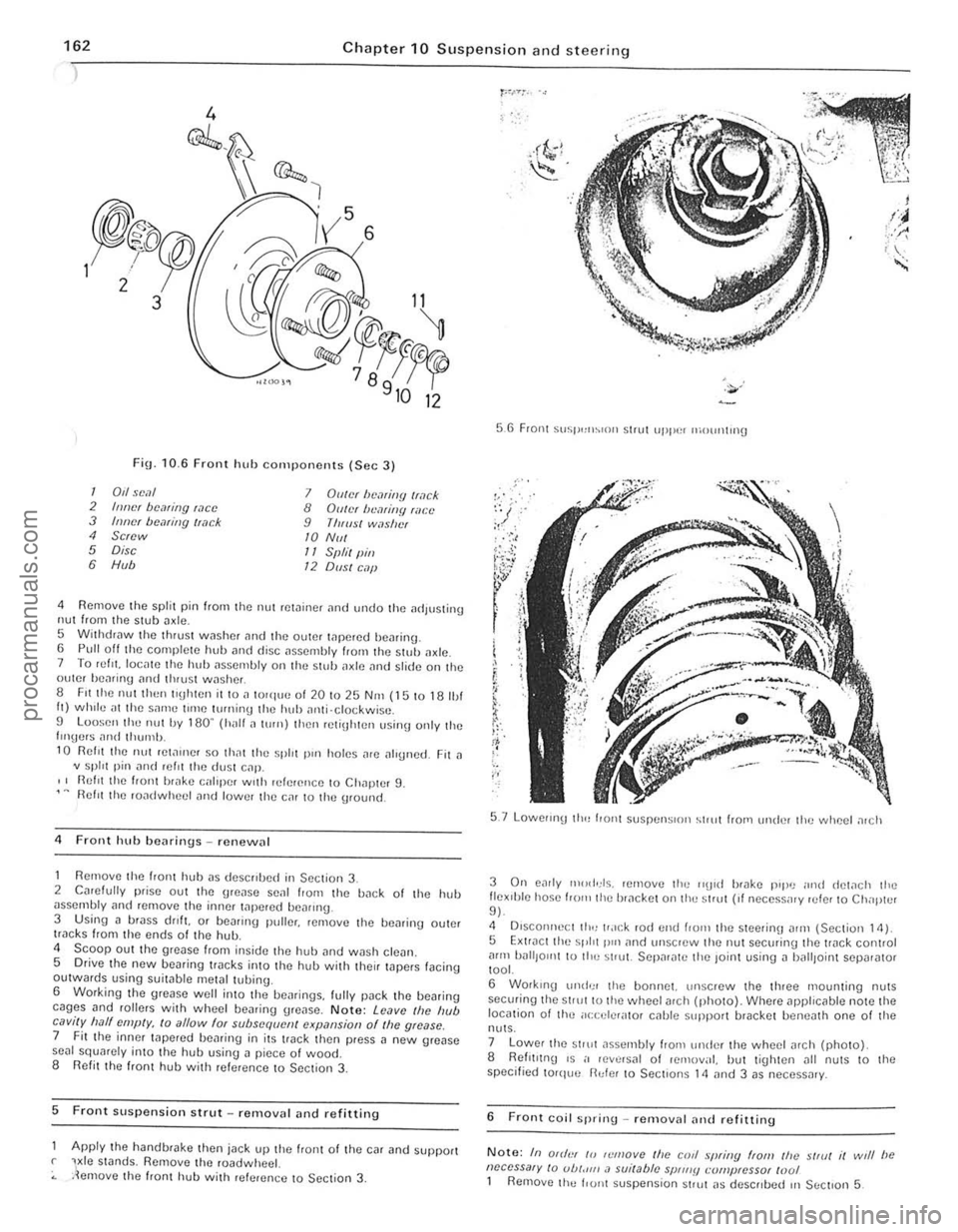
Fin· 10.6 Front
@",.,i
, 5
Y 6
hub cOnll)oncnts (Sec 3)
12
1 0,1 seal 7 Diller be,?li/!{J Iwck 2 IIIlIcr bcaring wee 8 GUiN Iwmitlfl filct' 3 Inner bemiJlg /I,?ck 9 ThlllS! wilslwf 4 Screw 10 NIII 5 Disc 11 Sf"il (lin 6 H", 12 01151 C.1jJ
4 Remove the split pin frorn the nul rC\;linCf and undo the adluS\ing nul from the stub a xle. 5 Wilhd,nw the thr ust washer and the outer tapered he,..ing. 6 Pull off the complete hub ;111(1 disc ilsscrnbly ffOIl11hc s tuh tlXlc. 7 To refit locale the huh tlSscmb ly on the stub il~lc <'Ind slide on the outer hc"rinu nnd II1
1 0 Rei" the nut ret;)u)Cr SO th~t the spill pUl holes ~re ~lIg"ed. Fit a
v split pin
2 Cmelully prise out the gre.lse senl Irom the b~ck 01 the hub
Scoop out the grease 110m inside the huh imd wash clea". S Drive the new bearing tr
glease well into th e beiu ings. lully p
Front Suspension strut _ renl0v
Apply the handbrake then jack up the Iro"t of thc car ilnd SuppOrt r ViC S\Jnds, Remove the roadwheel.
.lel1love th e front hub with referen ce to Sec lion 3,
56 Front SllSI',,"~'nll Slrut uppe, moullt"l{j
5.7 Lowellnl) 110" f'o"l SUSrlt''' S'OIl ~lr"tlro"'ll"der the wheel a,ch
I !:'~
!; ... ~
-;;
3 On e~rly n,,,dds. Icmove the "\lI d brake p'pu ""d dew ch Ihe flex'hle hose 1,0 '" the br.1ckct on thu strut (, f neccssilry ruler to Ch"p ll'r 9 ).
4 OlsconneClilHlu.u:k rod l'nd from the steer;ou n'm (Sect ion 14) 5 Extrncllhl' spirt p,,'
tool.
6 Workrng Ul1d'; r Ihe bonnet. un screw the three mounting nuts sec(Jl iog the 51'Ul 10 the wheel arCh (photo). Where applicable note the location 0 1 Ihe ilce ele r" tor cnble Slipporl bracket be ne3th one of the
nulS .
7 Lower the stru t ~ssembly from undl'r the wheel arch (photo).
8 Refll,!n\) '5 i' reve rsal 01 removal. hut ti\)htcn all nuts 10 Ihe
specified torq(,e fl"fe r 10 Section s 14 and 3 as necessary.
6 F ront coil sp ring - removal and refitting
Note: In Off"" /0 ,(:mo ve Ihe corl .~"{!finy ffOIl! the strut it writ be neccssa,y /0 ub/."" .1 sui/able sP"".
Page 164 of 205
Chapter 10 S uspension and steering 163
~~--,,$iJO
~~\~
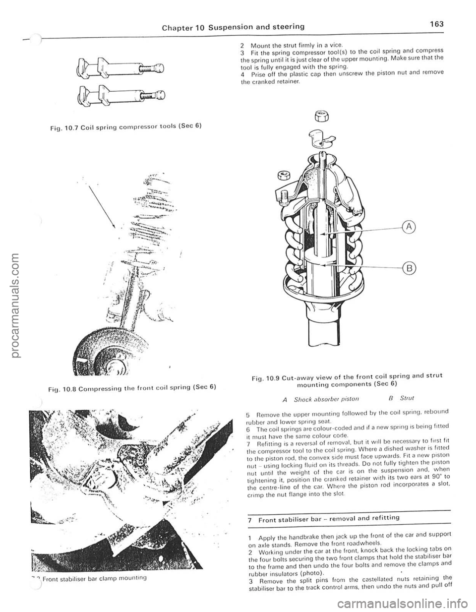
Fig. 10.7 Coil spri n g compressor lOo ls (Sec 6 )
\.
FiU. 1 0 .8 C o rn pressi nu the frOllt Goil spring ( S ec 6)
~ " / ron t stobiliser bar clamp mountrng
2 Mount the strut firmly i n ~ vice .
3 Fit t he spring compressor tool(s) to the coil spring and compress the spring until it is juSt clear of the upper mounting. Milke sure tho t the
1001 is f ully engilged with the spring.
4 Prise off Ihe plastic cap then unscrew Ihe pis ton nut ~nd remove
t he cranked
retoiner .
F ig . 10 .9 CU\·
ilWilY view o f th e front coil spring nnd strut mountin g compo nents (Sec 6)
A Shack absorbfN pis/ull B 51,,11
5 Remove Ihe upper 1110unling lollowed by Ihe corl spring. rebOllnd
rubber and lowe r sprrnU seal. G The coil springs are colour· coded ,1nd II a new sprong 's being I,!led
il muSI hilve the same colour code.
7 Ref itting is a reve,sal 01 removal. but il Will be neceSS
lhe centre.line of Ihe CM. Where the p iSlon rod incorpor
II~nge into the 5101
7 F ront stabiliser bar -removal
he hand brake then Jack up the front of the car and supporl
on axle stands. Remove Ihe fronl roadwheels.
2 Working under Ihe CM at the Irani. knock back the loc king tabS on the four baits securing tile two f,ont ct~mps Iha t hold the swb,hser ba r
t o the frame and then undo t he four bol tS and remove lhe clampS
,
I " I , ,
j
!
procarmanuals.com
Page 165 of 205
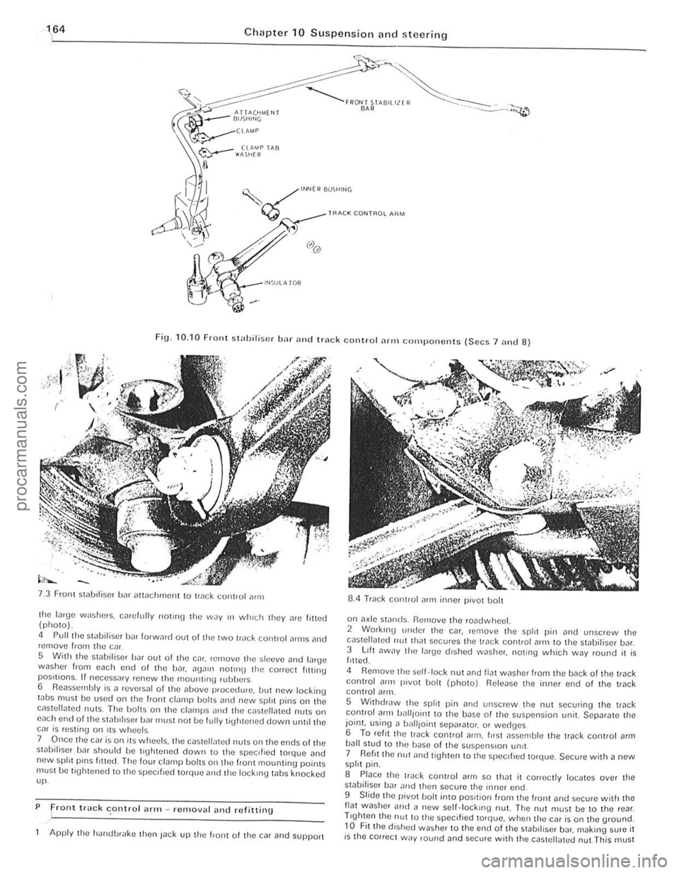
Chapter 10 Suspension and steering
~ l"Nfl> BUS"'''G
~ TRACK CONT~O~ AIIM
Fig. 10. 10 FrOllt st
Front Slilblliser bJr iltlilchmCIll to tr
5 With the stilbiliscr bilr out of tire Cilr. rernovtl the sltltlve Jlld lilrge wnsher from each end 01 the bar.
7 Once the car is on its wheels. the c(lsteli,lted nUlS on Ihe ends olthe st,)bifiser bar should be tl\[htened down to the specIfIed torqlJe .. nd new spill pinS filled The four cl(lmp bOilS on the IranI mountinu poinlS must he tluhtened 10 the specliled torque and tile lockIng whs knocked up.
P
Front truck conlro l ;lrm -removal alld refitting .
Apply the h'lIldl.>r
on a~le swnds. Remove the roadwheel. 2 Working ullde! the C(lr. remove the spirt pin (lnd unscrew Ihe cilslellmed 11111 Ih"t secures the trilck coniroi
5 WithdrJw the split pin [lnd Ullscrew the nut securing the trilck control Jflll battlOIl1 10 the base 01 the suspension unit. SCpar[lte the joint. using n ball,oinl Sepnr[llo,. or wed(Jcs 6 To ret, I thc lI"ck conlrol arm . fllsl JsscOlble the track conlrol [lrm bJIl stud to Ih(~ bilse of the suspenSIon !m't 7 Reflllhe nu! ilnd tighten to the speCIfIed torque. Secure with a new spirt pin.
S Place the track control (lrill so IhJt il conectly locates over the sliIbiliser hJr nltd then secure the iIlller end.
9 Slide Ihe pivot bolt into pOSItion "0111 the "onl and sccure w ith Ihe flat washer Dud il new scll.lock,no nut. The nut must be to the rear . Trghten the nUl to Ihe specified torque. when thu car is on the ground. to Fit the dished washer to the end of the stabll iscr bDr. making sure it is the cOllect way round and secure wit h the cas tellated nut This must
-------------------------.. procarmanuals.com
Page 166 of 205
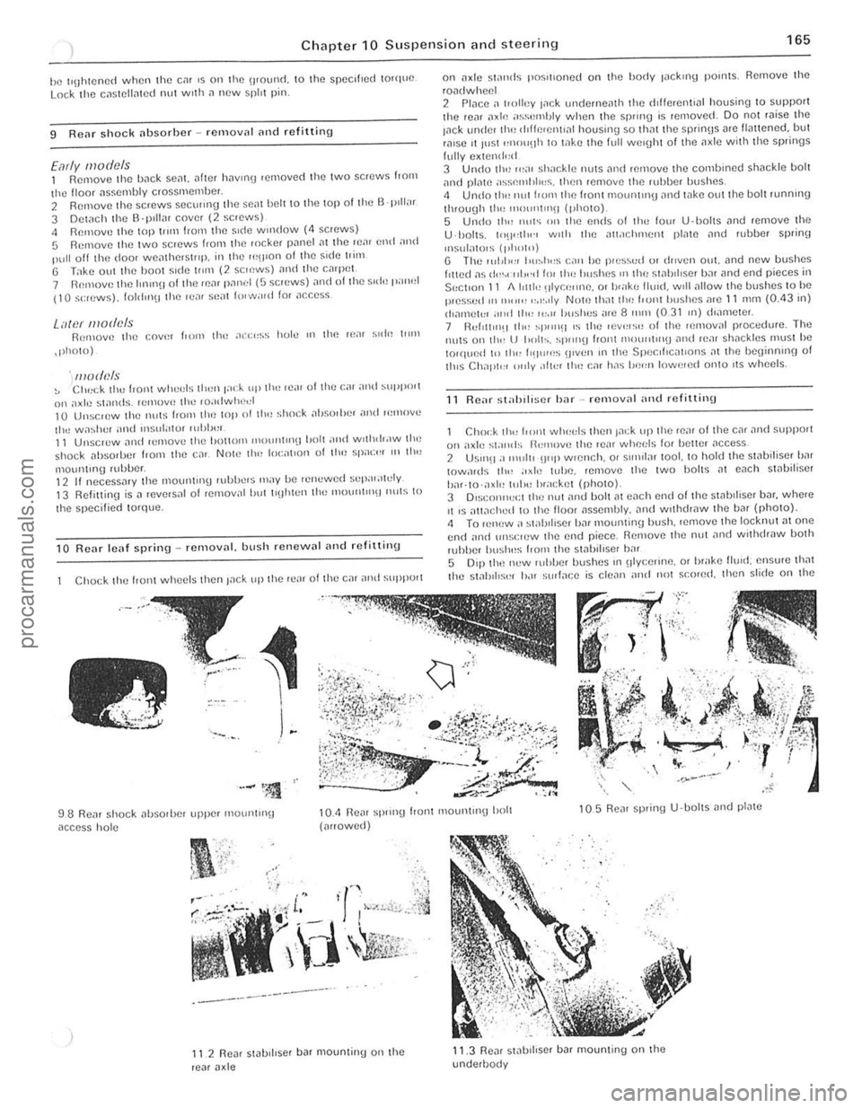
Chapter 10 Suspensio n and ste e ring 165
he IllJhlCned when Ihe em IS on Ihe '1IOUI1(1. \0 Ihe speclhe(1 100quO Lock Iho cnSlC\lnlCd I1UI wllh n new spill pin.
9 Renr shock nbsorbcr -rClllovnl nlld rofitting
Early models 1 Remove Ihe bnck sent.
.pholo)
. models ~, CIlr:ck the front wheds Ihun F":k up th,) rca r olthc (:;" and SUPI"lI l on "xle swnds. tCmovH Ihe ,o.ldwlwel 10 Unsc,ew Ihe nu(S Iron' tim lOp 01 III" ~hock ilhsnrhe, ilnd ,,:move the wa~her and ,nsul"l!)r rllhh,,,. 11 Unscrew nllll ,emove Ihe hollom IIH)l1ll1l"~1 holl and wllhd,.lW Ih(, shock nhsOliJer trom the cnr. Now tlw 100:"t,on of Ihe Sllacr:, '" II",
1110ul1lll1g lubber. 12 If nocessmy (he moun(lng lUhbers IIlay be relwwed sepal;l1cly 13 Relittinu is il reversal of refllov
C
hock I hl) hOI1l whl)l)ls then Inck up Ihe rl);11 of Ihe cm nntl SliPPOlt
98 Renr shock ilhSOlbel upper mOIJnlln\j
nccess hol e
"
-----------_.-
II 2 Re~, stabi llser b ar mountinu on Ihe rear a xle
on
U ·lJol ls. 10'1",1"., WIth Ihe all.lchment pl,110 ilnd fubber splinf)
Insulatols (1,1",11') U The I(lhll'" Ilu~h"s C;\l1 be p,es'>vd 01 dl1ven oul. lind new bushes fllted ns {I",.( ·"l,,·d 11)1 Ih" hushes OIl Ihl! s!ahd ,se r bnr lind end pieces in
SectIon 11 1I1r1l1t~ !lIY CI;"nc. or I,,"kr, flUId . WIll
R eM st"hiliscr har -rcmovnl ,,"d refitting
Chock tlr" from WIH't:I~ Ihen Jack up (h o ron, 01 the cal ~nd ~Hpport 011 nxle stands il"I1love Iho rear whet:ls fo, holtcr ilCCeS$ 2 USlnO :1 11111111 !J"P wlCnch. 0' sll1>llnr tool. to hold the swoiliser b,'r IOwa,ds 11r"
5 0'$1 Ih(~ new ruhber bushes III olycelll1e. 01 hrake lIuld. ensure that tho stabIlise, b.H ~(JIlnce is clc
procarmanuals.com
Page 167 of 205
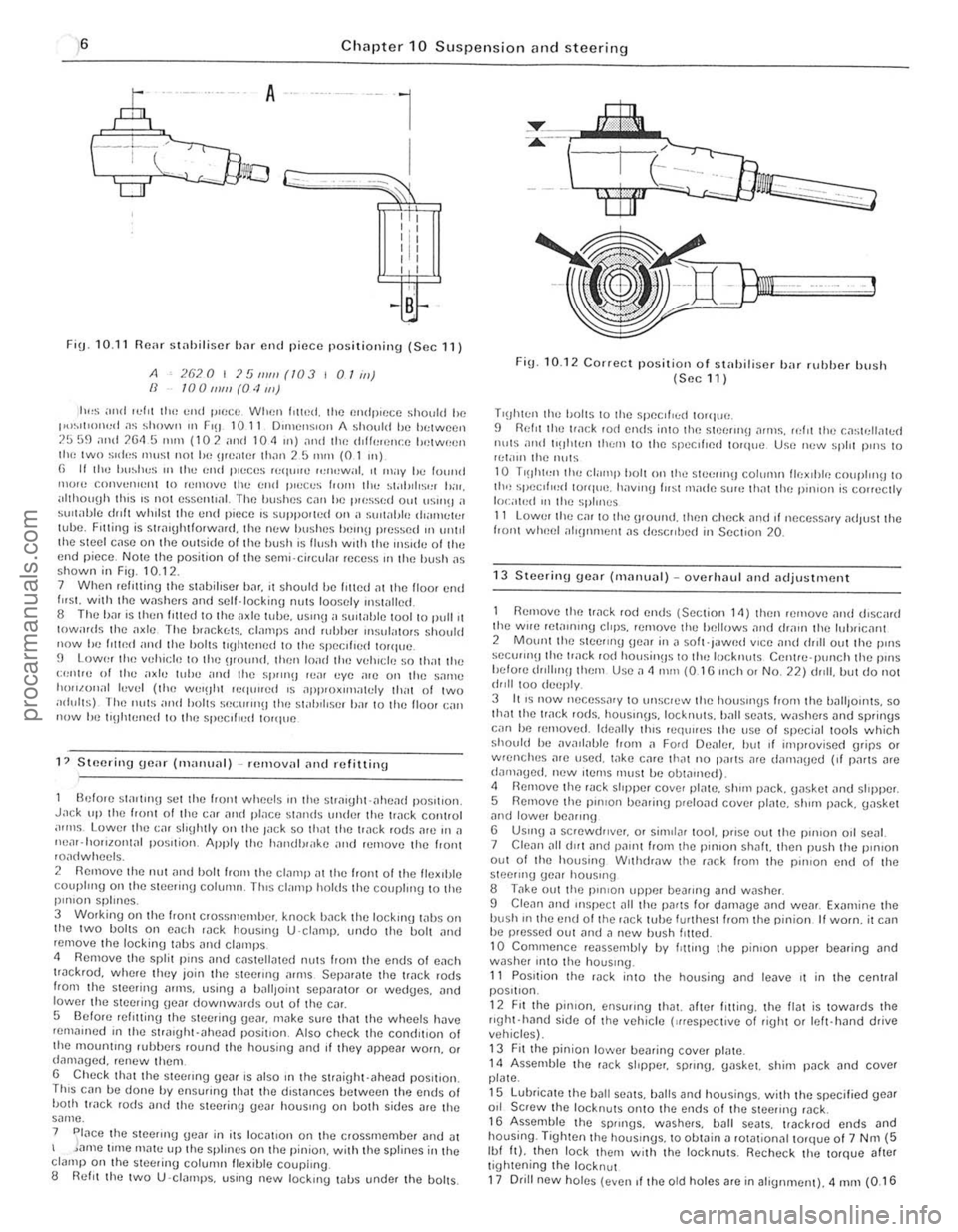
,6 Chapter 10 Suspension and steering
A
l
I Lr;=::;;r""~Jj'Q l
G-cc;;;;-~---~~~~~
, " I : I 'II
'I' , ,
, ,
FiU · 10.11 Fl(Wr stniJiliscr b;H flnd piece positioning (Sec 11)
A IJ 2620 I J!J 111111 (/03 101m) 100111111 (0·1 mJ
1"'5 ;",(1 ,0.:1'1 tile t;1\{1 sHoec When l ilted. the wHip'cec should he 1'''~'ll'''H,,1 .15 shown III FlO 1011 DIIIlCIlS'Oll A should he betweell ?!.i 59 nlld 2Gtl 5 ""ll (102 ami 104 JI') :lnd Ih" (h(fmcncc IWlwr!f!1l IllI! two s"I"5 IIll1S! nOI he \l'catc, th.1rl 2 5 nUll (0 1 m)
(l II Ihe IJl,~hcs "' II", (,11(1 11".:';'$ "''1''''<) """,wi,I, II 'llaV I", found "'O'e COI1V"Il
h",,/.ul1,11 h.'vel (the wUIOht ",qlllred IS dpp'ox,m
J.!Ck lip the front 0 1 thn C,lr and place s1
2 Remove tile nul ~lId holt from the elnmp at the front of tile fleXIble COllpll ll(1 on the steerm!j colllllln, Tills cl,IInp hOlds the couplln(J to the pillion splines.
3 Working on the front crossmemlier, knock hilek the lockmg wbs orl the two bolts on each IJck houslllg U ·C lillllp. undo the bolt ~nd remove tbe locking tabs ~nd clamps
4 Remove Ihe split pillS
Th iS cnn be done by ensuflng that the d,swnces hetween Ihp. ends oj bOlh trllek rods 1111(1 the Stec1inu geilr hOllslng on both sides ~re the same .
7 Place the stee"ng Uear in it s 10c
-,
Fig. 10,12 COfrect position o f stnhiliser bar ruhher bush {Sec11 )
T'!jht(:n the holts to Ihe speclf,(:{! to"lne, 9 Relit the I.,lck rod ends into the stO)(:IIn!) illluS. refIt (he I:a';[ellolted nllts and II!Jhten them to the slleclfl{)d tOlque Use new spill pillS to '!:t.nn the nuts
10 T'!lhten tho I:I,II"P bolt (HI the steeru'!J COItIllHI lIex'hle couphllU to 1f1n spec""~d torque. h,)vIlI!) fll~t rnil(\e SlJlOl tholt tlul pin lOll is cOlfecily 10(;"101(1 III t he S"III1CS 1 1 Lower the cm to tho urOllnd. thcn check nrld If neceSSo1ly ildJlIst the front whlwl ;III(J 'Hncnr 015 descrd)ed in Sec lion 20.
13 Stcerinu geM (Illanual) -overhaul <111(1 adjustment
Remove tlllltr ilc k rod nnds (Section 14) then .elllove 1)nd discard the Wile retalnlllg cliPS. remove the hellows and drall1 the I"hricant 2 Mount the stee"ng Ijear in
15 LubrientIJ the ball Seilts. balls and housings. with the specified gear 011 Screw the locknuts OntO the ends of the steeling (1)ck. 1 G Assemble t he sprlllgs. waShers. bJIl seJts. track rOd ends and housing. Tighten the hOllsmgs. to obwin a rowtionnltorque of 7 N m (5 Ibf It). then lock them w ith the locknuts. Recheck the torque alter tiuhtening the locknut 17 Drill new holes (even If the o ld holes Jre in aliunment). 4 mm {O, 16
______________________________ .1
procarmanuals.com
Page 168 of 205
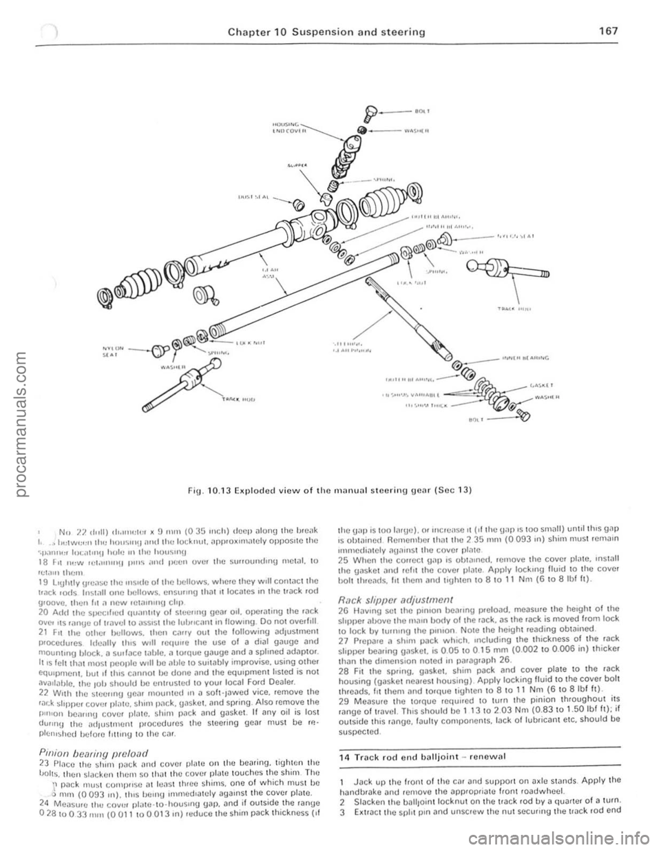
) Chapter 10 Susp e nsion an d steerin g 167
• ____ I,,, .. r,,,.,
.. , ..
"""""
/
..... . '''M'
""'''''' . ..... >'< '.' AU ... , ..... • Ut ~" ... '''toI •• " .. (', @
........ ' ........ -~~ ' • • ~Mr
.,,·,"'·'·,v"""" ".$"'" ''''.''''.",,~. ~
."', ~
F ig. 10. 13 Ellplodcd view o f the IlHII HHl I steering gear (Soc 13)
No 7.7. d"lI) ''''''''':1\:1 )( !) nit" (035 Inch) deep
22 Wllh the ~Ieelmg Ueilr mountud III iI so h·Jawcd yice. remoye the r,:u:k ~I'ppur coy", pl!!Ie. shim p,1ck. {lilskor. mid sprIng . Also "Jmoye the I"n'on bOilflll\J coyer plalC. sh im pac k and gaskot. It i1ny oil is lost dUIIIl!) thc adJustfllenl procedures thO steering gea r must be rl!'
plc'''~hcd hclore IllIIng to Iho cm.
P,niOIl bec1ring preload 23 PlilCC the shun p,l c k alld covcr pl1lle 011 Ihe bearinU. lighten the 'JOlts. then s lacken Ihcm 50 .hal Ihe covel platc louches the shim The \' pilck Illll~t (;omj}lIs e ill hlil st three sh ims. one 01 which musl bc Q m,n (0 093 In). tlus bern!) ullllledlalely agaIns t the COYcr plate. 24 Measure Ihl! COV'" pl,lle .to·housllIg gilp. and if outside I he ranUe 02810033 fllill (0 all 10 a 013 In) reduce 'he shim pack th ic kness {If
Ihe UilP is '00 li1rud. or Illcrei lse II ("the gap IS 100 slllilll) unlll Ihls gill) IS Ob'ilillcd Remembe r Ihat lhc 2 35 111m (0 093 III) shim Illustrcmillll
Immcdiately "UilIllSt Ihe cover pl;)'e 25 When the COIICCt \1.11) IS ohl!!lIlcd. rernoye Ihc coy!;'. pl"le. IlIs!.111 thc gasket ilild r efit ,ho coyer ,)IJ tc. Am)ly locklllg lIuid 10 Ihe coyer hOi' th.eilds. lit Ihem ;)"d lighlen,o a 10 11 N m (6 \0 albf It).
Rack sl/iJpcr .1djus(mell( 26 HilYlllg set thO pOlllon bearing preloJd. measure 'he heIght 01 the stopper il!J.OYC the IIIillll body 0 1 the rJck. as ,he rilck is moyed Irom lock \0 lock by turnIng 'he pillion NOIe thc height reilding obtained. 27 Pr CPilre ;l shim pack w hiCh. Including the thickness 01 the 'ilck sloppe r beJring {JilslIet. is 0.05 to 0 15 mill (0.002 10 0 .006 in) thicker than ,he dimcnSlo n lIoted In piuagrilph 26. 2a FII Ihe spring. gas ke t. shim pilck and coyel plate to 'h e ra ck housing (gaske l ncareSt housing) Apply locking lIuid 10 the coyer bolt thrcads. III them illld 10rque tigh.e n to 8 10 11 Nm (6 to 8 Ibl h). 29 Measur e thc ,orque rC(tullcd \0 lurn Ihe p inion throughout i,s mnge of I!.lY cl. ThiS should bc 1 t 3 10 2.03 Nm (0.83 to 1.50 Ibl It); if oulside th,s ,ange. Iilul,y componcnts. lack ollubriCilnt etc. should be
suspected.
1 4
Track rocl end balljo int -renew al
Jack up thc loon. Of thO Cil r and SUf)pOrt on Jx le stands Apply the halldbrilke ;)nd re!llove Ihe applopriil'C Iiont roadwhcel. 2 Slacken Ihe baliJo in l locknut 011 the track rod by iI quarter 01 a turn. 3 Extra ct the spl, t p,n Jnd unscrew thc nul securrng the !Jilc k .od ond
, .. • • ..
::
procarmanuals.com
Page 169 of 205
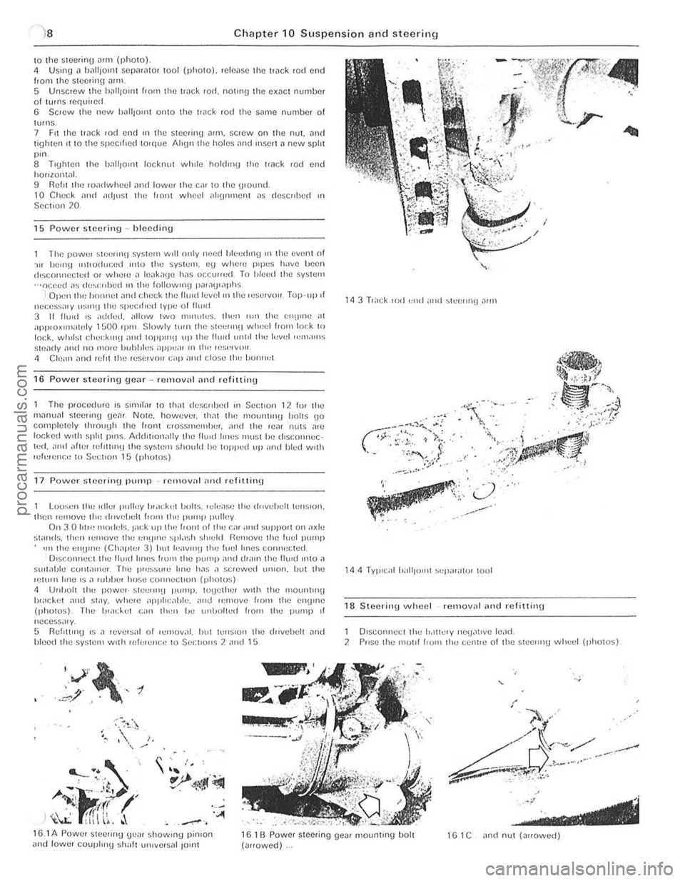
)8 Ch apter 10 Suspensio n and steering
\0 the SI(lcring Mill (photo) 4 USlIlg" 1)[lIi)onH SCpilriltor tool (photo). reh:o,lS(l the ['ilek rod end from the Slc(!rino ""m 5 Unscrew the h,"'IOlilt hom the ['
The power ~1P.elln\J SysHllll WIll only need blc",rhnfj Ifl the even! of . .., hell1\J Il1tl<)(hu:ed ",to the system. cu whcn: IH llI:S h;IV() IW(}1l dlscoI1l1cc«:d or whel() J Ifl.lk"(Je has occlUfed To hleed the system ···ocp.ed ;'s (1<,~<:"I)Cd III 1(11) followlllU l),l';)\J,,1I)hs
I Open llH~ hO'Hl()1 ,111<1 cl\p.(:k the Il",d h:v el "llhe Il'Sl'IVi'" Top·llp.t llucess;IIY IIS"'!J (Il<) spe.:II,ed lype of 11(11<1 3 11 11."d IS added. allow two "'''HlWS. th"l1 lUll 11m I;I\U"W at apPI{)xIIllntnly 1500 rp'" Slowly \illll lhe st'!""Il(! wheel 1,0m lo,:k to lock. wlllisl r:l\.,,;klllH and WPP"'!I up Ih e Ihlld unlll th" l"v,,1 ",m;II11S
Stf),li1y ;1<\<1 no molC hubhl"s ilPP":U I II tlw I"S,,,V,,II
" elc ;,", and refn Ihe r"servoll cap ami close II,,, 1>0"",,1
16 Power steering gear rellloval and refittinu
The p'ocedure IS Sllml", to thilt descrd)<)d III Sc(:t lon 12 10' th" m,10u,,1 steeling gC,lf NOlO. how"ver. lhm tile 111011111(1)(1 1)I)Its (jo cOllipletely tl1(ouyh lhe front e,ossmflmhe,. "nd the II.),,, nil IS a,e
I()(;ked wllh sphl pillS. Add,llon"lly lhe lIuld IIIH)S rnu~;t Iw lhsc.onnec · l"d. and atln' ,uI,Um!J the system ~hollid he loppud III' ,lnd Illed wllh lui"",,,!:,, 10 $"(;tl{>n 15 (photos)
17 Power steerillU pump remov;ll "lid rcfil1 ill\J
Loo~"n tl", «II.." Iwlley 1",lck,,1 b"lts. ,el..,ase Ih" d"ve!Jclt lellSlon. Ihcn ,emOVe II", dllvelu:lt I,,)m the P"'''I' pulley Oil 3 0 101", IIIO
h,;lc.k(,t ~nd st;)y. wlw,e ;1j)1'11 <:;,I)I". ,!Ill! ","'ove f'DIII Ihe CII!) "le (photos). The "",d..,1 C;'rl lh"" 1m (lnl)nlt"d flOm Ihe pUlllp of nccess;"y, 5 RellltlllU IS .1 ,ev,,'~al 01 I..,moval. "ul l"'Il~lon Ihe lhlvehelt ~Ild "Iced Ihe sy~IC'" wllh lek'e'll:tJ to Sec;1I0ns 2 ,!Ild 15
"V',~, , .,' , -t .~/ ,.
~
' ---... . . ' .. ' , "
A-i·J<'~ r~ _ I' .' If! h \l:: fITI \~, . '''''
~
•• :. ' 10)",', / )
. .. 'I.· L../,
'": .. ':;' ., .... ---,.
. .. .
18 S teerinU wheel removnl nnd rIllittinu
1 Dlsconneci the lodlielY nCU~lIve le,,(1, 2 PIISC Ih" mOllf hUIll Ihe celn,,) o f Ihe stcclln(j whc,,1 (photos)
15.1 A Powef SICCIIIl(j (je,, ' showUlU pinlOrl and lowe, coupl",U ~h,,11 un,vcfsnl lo;nl 161 B Power steering ue", mountUlg bolt (,,"owed) 1 G 1 C "nd nul (""owed)
.' ---------------------------------procarmanuals.com
Page 170 of 205
![FORD CAPRI 1974 Workshop Manual ,~
1 Unh"I"!lllo" pow,,, ~I""""!I pUIIlP "OI!! bracket
18 2A Rr,mOVII\!llill] st(;c:rOll\) wlu,cl mOI,f (emly models)
17.313 Rl]rtlov"!III,,· ,,,1,",, Ion,· fol1llil FORD CAPRI 1974 Workshop Manual ,~
1 Unh"I"!lllo" pow,,, ~I""""!I pUIIlP "OI!! bracket
18 2A Rr,mOVII\!llill] st(;c:rOll\) wlu,cl mOI,f (emly models)
17.313 Rl]rtlov"!III,,· ,,,1,",, Ion,· fol1llil](/img/11/56932/w960_56932-169.png)
,~
1 Unh"'I"'!lllo" pow,,, ~I""""!I pUIIlP "''''''''OI'!! bracket
18 2A Rr,mOVII\!llill] st(;c:rOll\) wlu,cl mOI,f (emly models)
17.313 Rl]rtlov"'!III,,· ,,,1,",, Ion,· f'ol1llile I'OW~' step- r'll!) pump
,
" , " ,
I
,1 , :ii~ ,
~i( '1 .-
~(
'.~ .'~' ,
, " L -17 dB olnd ~I,'y
a
~.' , 'II;.:" " . . ~ ....
,
,
----
18.2
8 Relllov",!) lil(: SWcnll'J wheel m01l1 (lalCr models)
',.~ ~ , ;,
r i.
procarmanuals.com