FORD CAPRI 1974 Workshop Manual
Manufacturer: FORD, Model Year: 1974, Model line: CAPRI, Model: FORD CAPRI 1974Pages: 205, PDF Size: 43.75 MB
Page 191 of 205
Chapter 11 Bodywork and fitting
I ..
"
;1' , ~
!
)
!
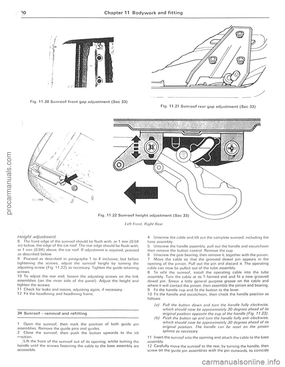
Fig 11.20 Sunroof front g
Neighl adjustment 8 lhll lIont edge 01 the SlUllool should he lIu~h with. o r 1 nUn (004 Ill) heluw. the edUe 01 the Cill loul Th" W
Open the sumool. then m,uk the pOSItion of uoth guide pm assemblies Remove the Uuide pins
)
llft the hom 01 the sumoo! Olll 01 liS opening. whIlst tu'ning Ihe handle unlil the screws l
4 Unsc,ew the cable and hit Ollt the complete Slln,oo/. uldudlll\J the b,lse ~ssemhly. 5 Unsclew the hnndle assen1bly. pllil out the handle Jnd escutcheon then ,emove the button conllol RenlQve the cup. G Unsc,ew the gem beming. then remove il. 10geth(1< with lhe plllJon_ 7 Move the cable so th;]t the g,ooved dowel pin ~ppe
Page 192 of 205
) Chapter 11 Bodywork ar\d fitting 191
..
C
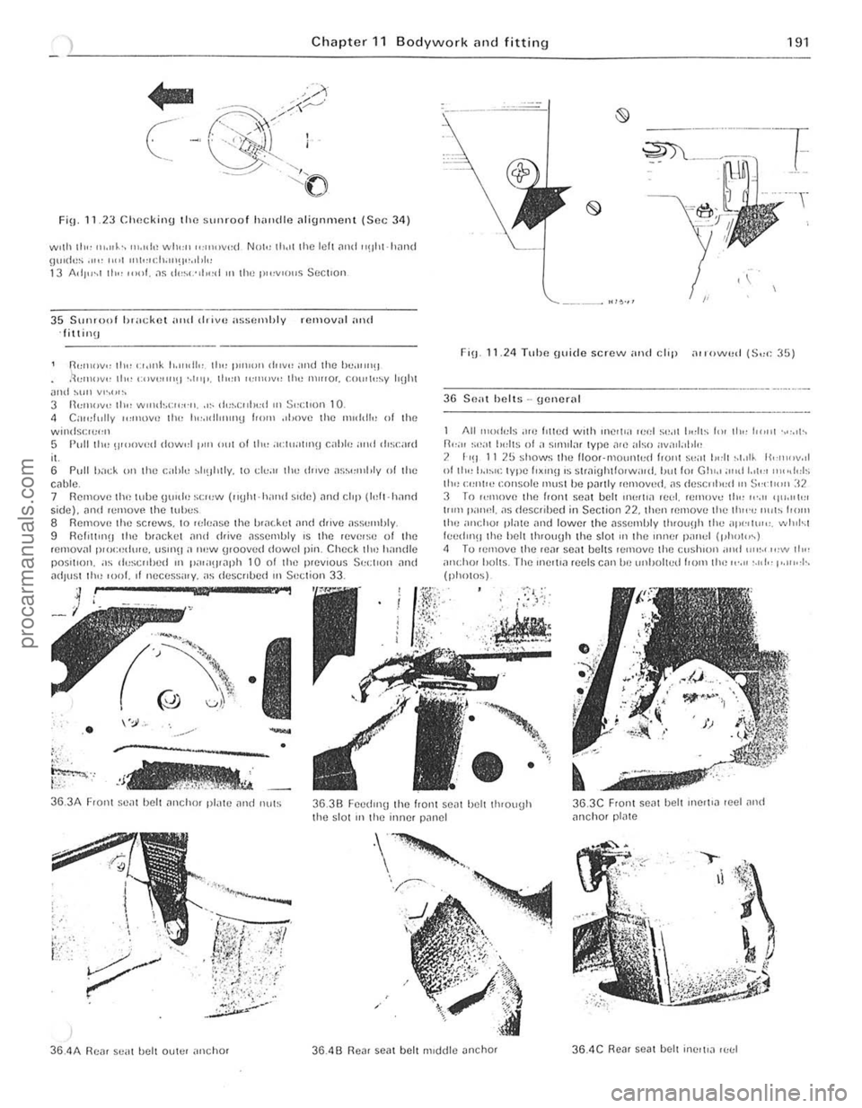
FilJ. 11.23 elweki"\) the sunroof hHndle nlignment (Sec 3 4 )
wllh th" ",.IIk-, " •• "I,~ whO:1l "",,",vt:d NOh! th.,t tile lelt ,lnd "oht·h1lnd gUltit,s .",' ,,,.( "'I,,"cil.LI'!I.,,,I,I,, 13 A,il'''1 II,., ,,",1 , .1<; d"~<-"I""I '" 11", I""V'()US Soctlon
35 Sunloof h',"ckcl M"t d .. ivH n%l)mhly rClllov
til" cr .• Ilk to.lt,dh: til" p"I,on dllv" and the hu"",,!) tl,,, ""V''''''') '.1"1'. II"", ""'IIIV" 11't: m irror, f.()"'t,:~v IIUht
6 Pull bold, Oil Ihe cabl" ~h!lhlly. to (;1",,, 110" d"ve ir~;~,,"'I,ly 01 Ihe cable 7 Reillove Ihe tulle \JlJld'~ S(;"'W ("!)hr·h,u,,l s'de) ,l"d clop (Idr-hand side), ;]Ild remOVO Ihe tull,,~ 8 Ren,ovr~ the screws, 10 rele,lSe the b'ilcket ;]nd dJ1ve ilsse",hly. 9 RehwII!) the ur,1t;kcl il'1(1 drive ,lssembly 's Ihe reV'IIse of the ,emov;,1 p'ocndwe, US"'!! a ""w u,ooved dowel pin. Check 110" h;,ndle
POS'I,oll. ;'S rl,,~cr,lJed ,n I"";'()'ilph 1001 Iho prev,ous Sc,;I,O" and ;]dJu~1 Ih!) "'01. 01 necess,,,y. as de~c"l>ed III Seelion 33.
""'
, !
• . --.-" -
'---:----
-'j~
•
"
FiU 11,24 Tuhe guid e screw ilnd clip a llow"d (S".: 35)
36 S!la t helts -IJener .. 1
All ",,,dels ;H(J hllud with OI1Clt", 1(,(,1 S(!.!I 1,,,11:; In, 110" 1"'''1 """h n",,, ",,;01 ho:llS 01 ,1 s",ul,,. type ,Ire also ilvntl;1I,1,~ 2 I '!I 11 2~ shows Ihe 1I00r -rllo,u'h,(1 hunl S,,"1 1",11 '.I.rl~ Ikn",v.d of II", I>,'~I(: Iype hxu)!1 r~ Sirilitlhlfo,w;"d, IHlIIor GIII,r ;r"d L,("r """Ids II", C""I", console m"SI be parlly removed, ol~ descrrh"d "' S'·,·I,,'" ]2 3 ro ""nove Ihe frOni ~eill belt rn",I,;] re,,1. u~m()ve IhO! "',,, '1","1", III'" POI""', i'S descllbed in SeClion 22. Ihcn relllovc Il>e Ih",!: "ub I,,,,,,
Ihc ,,,,chu, plillC ;rnd lowcr thc nssemtJly Ihrou()h Ihe ;rp"'I\"". whtl~1 feed",!! Ihn hel l Ihrough Ihe sial "' Ihe "ull,r jJ''''ul (ph()I"~l 1 Tu ,emove Ihe ,eilr seill belts remove Ihe cushrun ,,,,,I "",., ",w II",
anchrll holls The "'erlra reels Ciln ue lI"hulted I'om tIH~".II ,.,,10, 1"""'1-. (pholos)
36.3A F,ont S(!ilt belt ilnchor pl;,tc ilnd nuts 36.38 Feedlll\l Ihe honl seill belt IJuouUh
Ihe slOI III Ihl! inner pilllel
36.3C Front seill bell 1llP.,I'il ,eel ;]nrl
;]Ilchor pl,lIe
36.4A Reil! scm belt outer ,lIlehor 36.46 Rear seal belt m,ddle anchor 36.4 C Rear SCJt bell inC'l'a u:(;1
procarmanuals.com
Page 193 of 205
19 2 Chapter" Bodywork and fitting
)r-------------------------------------------------------------------- ---
-, jj
t~
' ',.,,,. '
·l .. ..... ..
-.. ""~" . . ,. ~ lOO'''''''''' ''''''''~' "'" , .. ,:.'~.:~'"''''.'''"''''~'''
".L. e' ' ...... "" .,,,~., ,
e: ii)<> .. , ,
'----;,' J
r:~
" , • IJ( .. , ",
(~
" ., -"' '' ...
Gj ...... ".
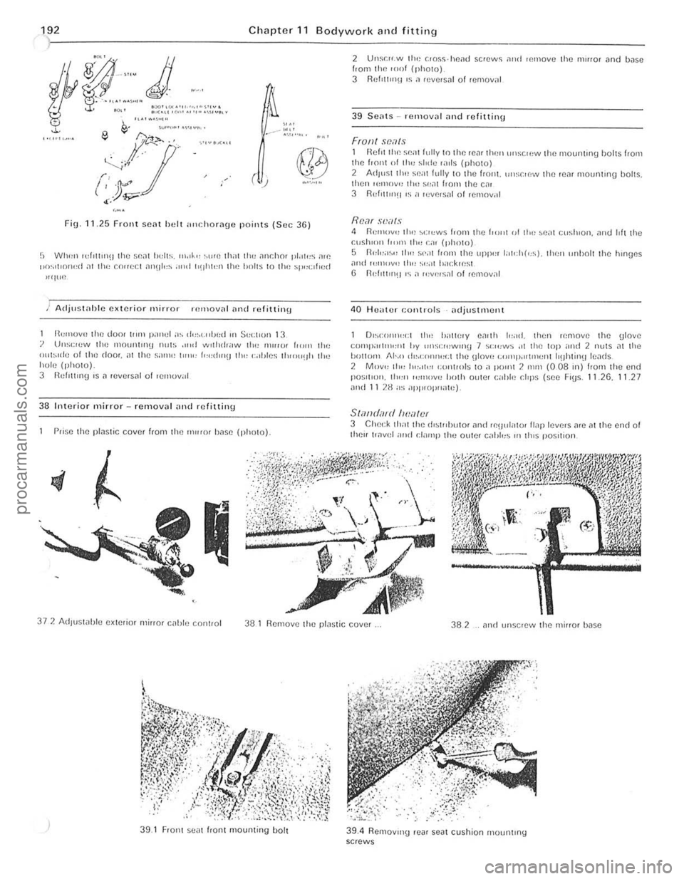
FiU.ll.25 Front sen 1 h e l! ;,IIchorilu e points (Sec 36 )
!; Wlu,,, ",!oWIl!) Ihe se a t hcll~. rn," " ,."'fl thai lin: .l1H:hor pl.,u,s ;H() "n~'t(()lu,d n! Ihe co"eCI an!ll,,~ a"d 1'!lilll,n IllI! h()lt~ 10 11m sp,,(:,I',~d
"'J'lI!
) Adju slilhle exterio r .n ir ror HlInovnl ilnd refittinu
1l,,,,,OV'!
Ih~ doo< 1"1ll panel "~ ,lo:~,-"lJr:d .. , S"C\ ,orl 13 ? Un~c'cw Ihl) mOunllll!) nul,; ... ,of wllhd,aw 110" 'lHllll! f""" IIor: ()ul~"le 01 111() doo,. ill Ihe S,Hll<: I """ I""(!")~I 1Il1' (,,,hies I Io",u,)h liln hole (),holO). 3 fkllltlllg ,s n ,eve'slli 01 ,ellloval
38 Interior m ir ror -remova l ,mel relittinu
P"se Ihe p!nstic cover 110m the nlllio r bilsc (photo)
2 Un!":" .w the C«)~~·heillj scr~wS nnd ,r.move the IlHr fO' and bilse
/,om thp. ,o"f (photo) 3 Rd,tI'fln 'S n ,e"crsal of remo",,1
39 S eilt s - .e lllovill illle! relittin\!
Fronl scals 1 Hef,1 tllp. seat fully In Ihp. len, Ihl'" \ll\sc,ew Ill(! ",ount,n\! hails from the f,ont "I tl", ~fode 'ilil$ (photo) 2 Adlust Ih" seat fully to the fran I. unsc'ew Ihe r~m [nOwllong boits. th~" ,e'nn"" th" SI,,11 frail' the eil' 3 R(,f'II"'~1 os a ,cvllosill of 1I;1110V,oI
Rcnr sl.'als 4 RCIIl"V", lilt) ~';'"ws hom the 10",,, "I th" ~e,ll cosh,on. nnd 1011 the cush,on f",m Ill" cn, (pholo) 5 n"l"a~" 110" s,';l1 from 11m LlPP'" l:oIch«; s). 11«,,, ,,"bolt the hmUes nlHl ",n,,,v., 11<" S""I i>;)cklr:s l
6 n"roIIO!l!! o~ a ",v,~os"l of removal
4 0 Huatflr (;onU'ols
) 39.1 F,ont seat fron t nlounting bolt
39_4 RernovlllU ,ear seat cushion rnoulllIng sClews
procarmanuals.com
Page 194 of 205
Chapter 11 B odywork an d fitting 1 93
)~--------------------------~-- ------------
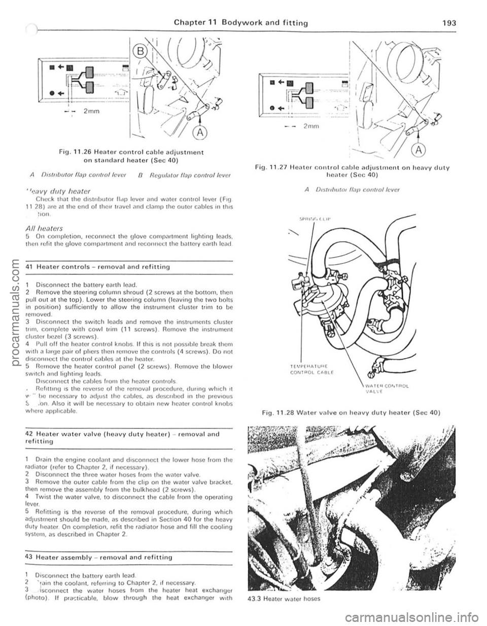
Fig . 11 .2 6 Heilter control cil blc 1Hljus tm ent
on SlHn (IMd heilter (S ec 40)
A (),.\·/"UlI/Ot flajl COII/ro//aVllr 8 I/Cgll/;I/O( Il.7p con/fo/h'vt'f
"'!ovy dilly IIfHltOf Chl.-r.k thilt Ihe d'Slflhutor 1I"p levc. ,HId WilIC, cont.ollcve. (FlU 11 28) we 011 Ihc cnd ollhl)" Ir,"vel ilnd clamp Ihe oulC, cablcs "I \IllS lIon.
AlllwMCfS 5 On complct ion. reconrWC I Ihe ulove comp;lr llllent liUhtinU leads.
Ihen lelil Ihe Ulove COllll)nltrllell1 nnd reconnet;1 Ihe hnllelY emlh len {1
41 H OMe r controls - removal and refittinu
1 Disconnect Ihe ballery eimh lend. 2 Rcmove Ihe s teer ing column shroud (2 screws D tthe bOliO",. then pull oul .lIlhe lOp). Lo wer thc stee.ing column (lel\Ving Ihe twO bOltS in position) sufficiently to ullow t he inst.umenl cluster I rim to be remOve d. 3 DIsconnect Ihc switch 10MIs ;lnd remove the instruments cluSIO' t"m. COllll)lot e with cowl "im (11 screws). Rcmovc the instrumont clusle r l!clOI (3 scrcws). 4 Pull oil Ihe hOiltor control knobs. II t his IS 1I0t possIble I>
.. hc neccssmy 10 adjust th e callies. as dl.'SCfllled III the p.evlous ::. .on Also it w,1I be necessary to obtall1 new hCille. control knobs where npphcable.
42 HCHte r
water villve (hellvy duty heater) -IC lll oval an( 1
refittin g
Drilin
the engine coolant ilnd dlsconncct tho lowe. hosc !rom th c ,aulato. (,efe. to Chapter 2. II necessary). 2 Disconnect Ihe th.ee water hoses f,olll tho Wille. valve. 3 Removo the OUWr cilble from the clip on the WilWr v~lve bracket.
Ihen lenlOve the assembly from the bulkhead (2 screws). 4 Twis t the wate r valve. to disconnect the cable IrOI11 the operilt ing
l ever .
S Relilling is Ihe reve'so of the removal p.occdure. during which ~dJustl\lcnt should be m~do. as described in Section 40 fOf the heavy duty healCf On completion. re li t the rudiutor hose and fililhe cooling SYSt(:rll . us described in Chapler 2 .
43 Heater assembly -re mova l and re fillin u
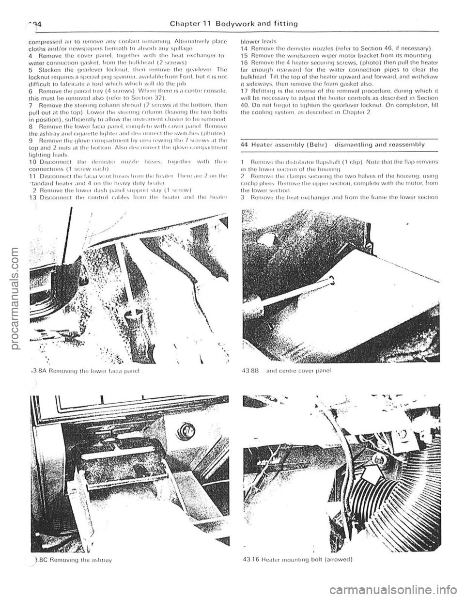
1 DlsconnOCl lhc tJiltH:ry ea.th ICild. 2 -,,,in the COOIIlI1l. rei!;fliny 10 Chllpte. 2. II neCCSSilry. 3 sconnect th e Wiltcr hoscs from the hoale. he;!t e.chanuc. (phOtO). II I>
- ' = 1 --·-~··""I c,
'1,:-1
F ig .
11 .27 Heale r COl\trol cilhle ncJju stm ont on heilvy cJllty hl"latot (Sec 40)
A /),., ·{n/w/III If,}!, CQII/lo/ft'vct
Il"'·I·"1>.1 VU[ CO""'OL U·OL(
".."Tt"CO""'OL -NIL\[
Fig. 11.28 Willer varv e o n heavy duty heilter (Sec 40)
43.3 H eiltel water hoses
i , , . ,,
"
procarmanuals.com
Page 195 of 205
~'l4 Chilpter 11 Bodywork and fitting
~I-----------------------------------------------------------
complessnd ~" to IcmOVI! ,OIly I.nolar ,,,",,,"1111)11 Alh,,,)attv,,lv pl;)c" clothS JII,l/or I1CW~I)ilP'''S 1)(!I\!;o1th In ,11",,, 1, al'V SI"lld!!" 11 Remov" thc (.over pan,,1. tn!I"lh," wllh II", lw,'t nxch'''''Ie! 10 watel cOI"'~~(:IIOIl \J,;~k...r. f,om th,~ IlLII~I"',1,J (2 ~r:tI~WS) 5 SlackclI till! !1"o1ll~N'" l(l(.k"(li. 111,·" ""''''Vl) Ihl) !)"oI,I,~vf)f The locknut IClIlIlICS a 5p,,(;'al p"!J Sp""""'. ,IV,HI.lhl" hOIll Foul. hllt It IS lIot
d,fficult to 1;)10'11:;\1" ,1 10,, 1 wh'<.-II which wIll do Ih" 1010 6 Rcmove til.., I'n,r,d I';IV (1 ~':II!WS) WI""" til",,, IS a celli'" fOI1S<)t.i. this must hc ICmOVl!ri "Iso (lcfcl to SC,.t'Oll 32 ) 7 Remove Ihe strJ(!IIllli coll,"m sl"olld (2 ~n"ws al tl", hOllUm. th(!n
pull out
J.se Rel\\ov,n\! lire il~ht")V
hlowef If!a
43.16 He,ltcI tnounilng holt (a,rowed)
procarmanuals.com
Page 196 of 205
-' ,J"i
<~
195
2
~ --3
4
,
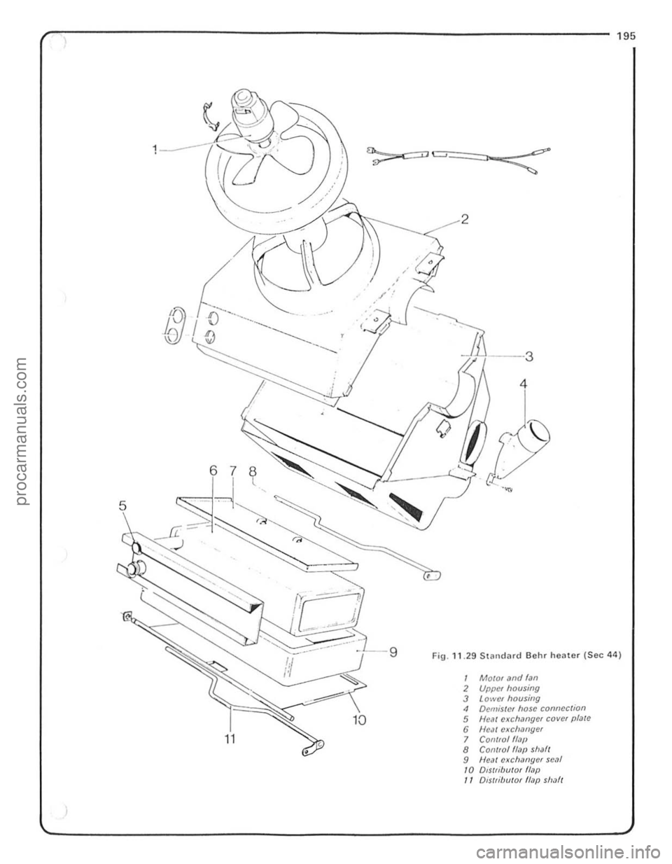
Fig .1129S . tilndard Beh r heater (5 1 ec44)
2 Mowr ,1nd f"n 3 Upper housing 4 Lower housillg Deli/isle, " 5 Helll CXChaosc connection 6 Neil l crl /lye( COVIN plale 7 C ... liJllger 8 Oll/rol {hll' 9 ;,001l011/,1fJ shaN cal CXC hiW 10 Dis/rib I ger sC
J
procarmanuals.com
Page 197 of 205
)96 Chapter 11 Bodywork an d fittings
of the housing, then remOlle the heal exchanger from the 1ramc and lake ott the fOilm pilcking. 4 To remove the distributor flap from the housing. remove the clip and withdraw the conlrollcvcr sideways. 5 Remove the rcgul<110r flap from the lower section of the housing, Bend bJck the 2 claillping straps sulticicnlly \0 enable the conlrollCIICI 10 be withdrawn (liter i, hilS been turned tow;1rds the side, then remove the regulating flilp. 6 Remove the retaining straps for the blower mOlor cap. by pressing outwards from the inside uSing 11 screwdriver. 7 Deweh the mOlOr from the upper sectioll. Disconnect the motor leads, remove til(! <1 rewining clumps and remove the motor and filiI inw,uds. a When reassembling. positIon thc blower mOlOr so that the clectric
11
11 The remainder 01 the reassembl y procedure is the reverse 01 the
r emova l procedure.
45 Heate r nssenlbly (Smiths standard and heavy duty) -dismantl ing and reassem bly
Standard he,1ler I Remove clips A and B (Fig. 11.32) ilnd remove lhe heater housing
sidc cover complete with flaps (15 screws) .
Heavy duty healer 2 Remove clip A (FIg . 11.32) olnd remove thc hcater housing SIde cover complete WIth flaps (15 screws)
All he,lIers 3 Remove thc heat e~chnnger nnd 10,1111 sen I. <1 Prise off the c"clip nnd remove the Ian I.om the blower motor shall. 5 Detach the blowe r motor from the support (3 nuts and holts). 6 Reassemhly is the reverse of the dismantl ing procedure.
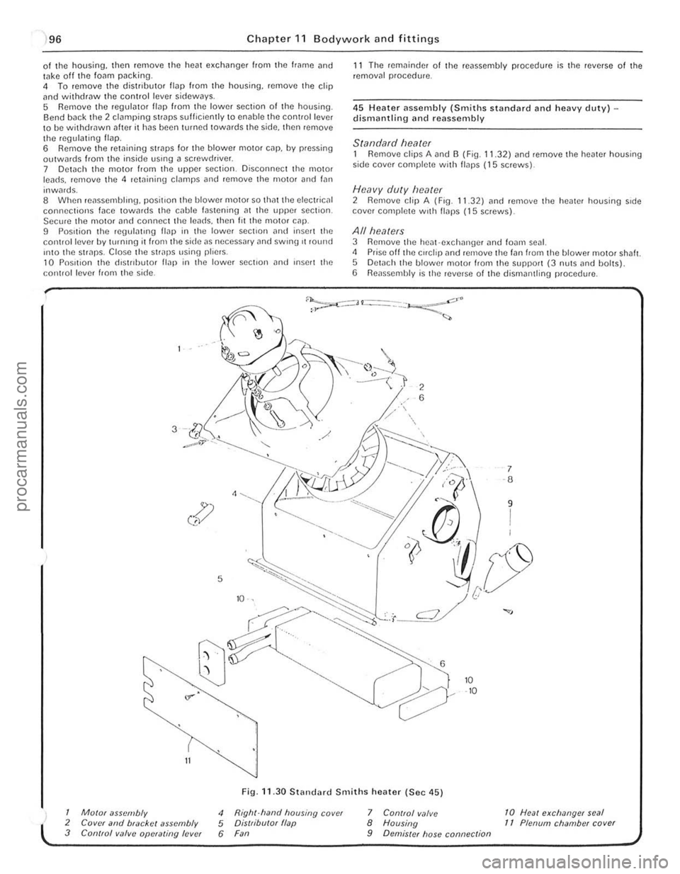
Fig .
11.30 Stilndllrd Smiths h eater (Sec 4 5 )
1 M%r assembly
2 COVt·( and black!:t assembly 3 Control valve operatillg le vel
4 Righr·hand housing cover 5 Dis/ributor flap 6 Fan
7 Control v
-------------------------------~ 灲潣慲浡湵慬献捯m
Page 198 of 205
7
) Chapte r 11 Bodyw ork an d f ittings 197
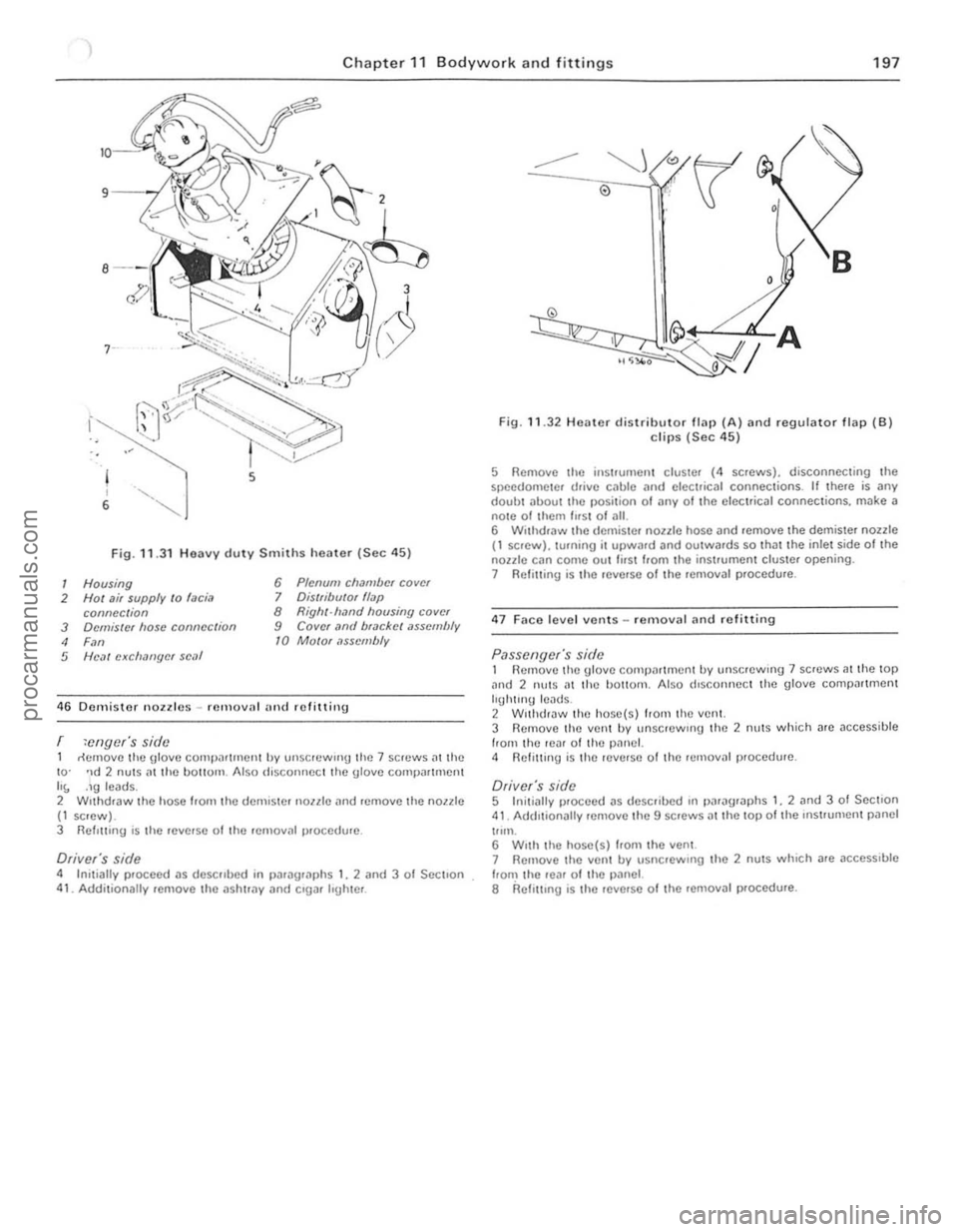
Fig. 11 .3 1 H eavy duty Smith s h eate r (Sec 4 5)
1 Housing 6 Plenum chamber covel
2 Hot ai, supply /0 laciil 7 Ois/fibulor flap
connec tion 8 Right·hand hOllsing cover
3 OrlniSlef hos e connectioll 9 Cover ,ltld bfackel assembfy
4 F.ln 10 MOIOI .lSscmlJly
5 HeM exclllmgcr scM
4 6 Dcmister nOlzle s -remova l alld refiuing
r :cngcr's side rtcnlOve thc glove COlllpiUll1lCllt by Ullscrcw"'9 the 7 screws iI the to · 'ld 2 nuts (ll lhe hall()m. Also discoIH'oG I the glovo compJrlrllCIl h\, ,19 Icads. 2 WIthdraw lhe hose frorll\he dCnllSlC . noale (lnd remove the noule (I sClew ). 3 RefItting is Ihe rev erse 01 the .cmovill Il' occ du.e .
Driver'S side 4 Initially proceed a s descullnd in palagr,lphs I , 2 and 3 0 1 SectIo n 41. Additionally remove th O ashu".,. and CIgar Irgluer .
o
Fig. 11.32 He ate r d istributo r flap (A ) and regulator flap (S ) clips (Sec 45)
5 Remove the inSllumen l cluster (4 screws ). disconne<:ling Ihe speedomele . d.ive cable and elect.ical conneClio ns . If lhere is any doubl about Ihe position 01 ~my 01 Ih e ele<:trical connec tions, make a nOle of them fn SI 0' ,111. 6 Withdraw the d ernis te . noale hose i1nd remove the demiste r noule (1 scre w), turning it upward and ou twards so thililhe inlet side 01 Ihe nonle can come ou t first from th e in strument cluste. opening. 7 R efiuing is th e reverse of Ihe removil ' procedure .
47 Fac e level vonts -removal an d re litting
Passengers side 1 Hcmove Ihe gl ove comparlment by unsc!ew 'ng 7 SCfcwS at t he lOp ;Uld 2 !llltS ,11 th e bottom . Also drsconnec t Ihc glove compar tmen l Irghlrng leads. 2 Wrlhclraw I he hose( s) h om th e vent. 3 Remove the vent by unscrewing the 2 flu lS which a rc access ible from the reilr of th e pan el. 4 Rcliu in\j is lhe reverse 0 1 the relllovill procedulC.
Driver's side 5 Inil iall y p'oceed as described rn paragr aphs I, 2 ilnd 3 0 1 Secti on 41. Addrlionally remove Ihe 9 screws at the lO p ollhe rnstrumenl pilnel tllm. 6 W,lh the hose(s) Irom the vent .
7 Remove the ven l by usncrewlIlg the 2 nuts which i1re ,1ccesslble from the reM o f the p.,lnel. 8 Relru.ng is the reverse of the remova l procedure .
••
,
1 ' I
procarmanuals.com
Page 199 of 205
)
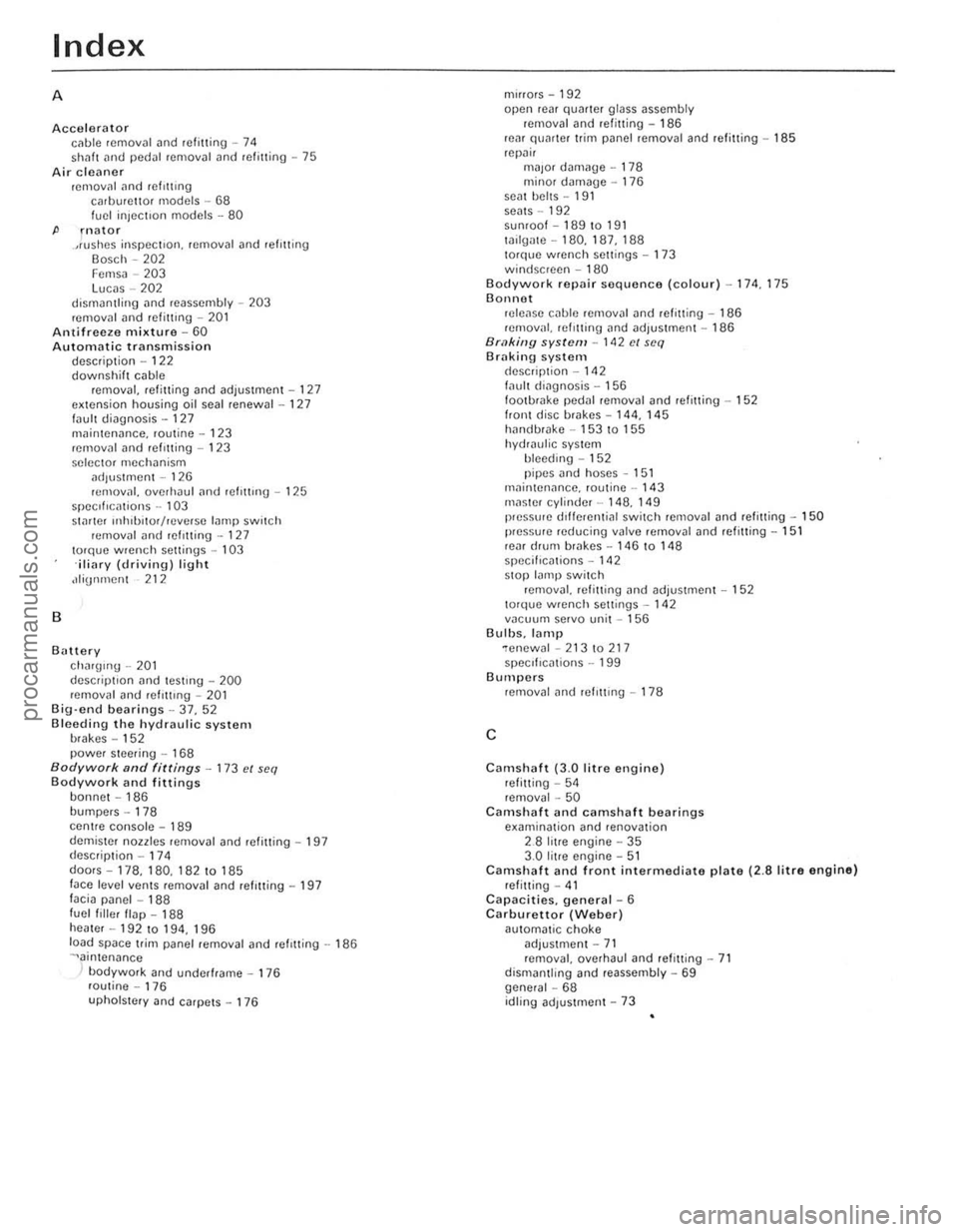
Index
A
Accelerator cilble removal ilnd refining -14 shnft ilnd pedal removal and refining -75 Air cleaner removill Jnd ref,nrng cal buren or mod cis -68 fuel injecllon models -80
P rnator .,rushes inspecllon. removal and refilling Bosch -202 Femsa -203 Lucas - 202
dismantling and rcassembly -203
removal and refining -201 Antifreeze mixture -60 Automatic transmission descrip tion -122
B
downshift cable removal. refi11ing and adjustment -121 extension housing oil seal renewal -121 faull diagnosis -127
maintenance. routine -123
removal and refOlting -123
selector mechanism ildjustment - 126 rcmovill. overhaul ilnd refl11lng -125 speclflf:iltions -103 SI.1r1er IIlh'bilm/reVerse lamp switch remov
demister
noules reOlov
doms-178.180. 18210 185 face level vents removal and refItting -197 facia panel -188 fuel filler flap -188 heater -192 to 194. 196 10
uphOISlCry
and carpets -176 mirrors
-
192 open rem quarter glass assembly
removal and refitting -186
re~r qllMlcr trim panel removal and refitting -185 repi'lir millor damaue -178 minor damage -176 sent belts -191 seats -192 sunroof-189la 191 lailgate -180. 187. 188 torque wrench scuings -173 windscreen -180 Bodywork repair sequence (colour) -174, 175 Bonnet release c
Camshaft (3.0 litre engine) retitting -54 removal -50 Camshaft and camshaf t bearings examination and renovation 2 _8 litre engine -35
3 .0 litre engine -51 Camshah and front intermediate plate (2.8 litre engine) refilling -41 Capacities. general -6 Carburetlor (Weber) aulomat ic choke
adjustment -71 removal. overhaul and retitting -71
dismantling and reassembly -69 general -68 idling adjustment -73
procarmanuals.com
Page 200 of 205
)
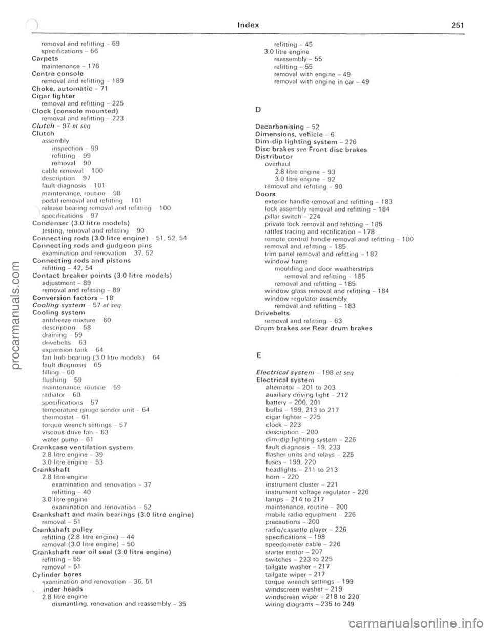
rernoy .. ' and refl Uing -69 spcc,'iC
(IlIvchells
G3 e~p:mSloll I nnk 6<1 Ian hub l)()nllllH (30 hilI] 1110<1111,;) 64 f~ull (II;)Ul1osl~ 65
flll".U -
60 lIush"'9 59
",nmlen,lncc. roullllC 59
'ild,nlOr
GO speclficn llon5 57 lem,)er;!lurc unuuc Sf:n(Ie. unil -134 IhcrmOSl<11 -61 10Htlle wrench selll ngs 57 VISCOUS drlv\! 11'111 -63 W1)ler IWIllP 61 Crankca se ventiln tion system 2.8 tol'c engine -39 3.0 rillC engine 53 Cranksh1)ft 2.8 li l.e engine examinat ion nnd rcnoviuion -37 refilling -<10
3 .0 til.e cn gine examination lind renOV1'l110n -52 Crankshilft and main bearings (3.0 litr o engino) removal -51 Crankshllft pulley refitting (2.8 hIre engine) -44
removal ( 3 .0 litre engine) -50 Crankshaft r ear oil seal (3.0 litre engine) .efllling - 55 .emova l -51 Cylinder bores ~xaminalion and .enovation -36. 51 Indo r heads 2.8 titre engine dismanll ing .• cnova lion and .eassembl y -35
Index
D
refining - 45
3.0 litre engin e
. eassembly -55 refining -55 .emoval wilh engIne -49
removal wil h engine in car -49
Decarhonising -52 Dimensions. vehicle _ 6 Dim-dip lighting system _ 226 Disc br1lke s scc Front disc brakes Distributor overhaul 2.8 hlle engIne -93 3 a !r1l0 cng,ne -92 rcmoval and r efIlling _ 90 Doors eXle.io. hllndle ,emoval and refilling - 183 lock 1Issernbly removal and .efilling -184 pillar swi lc h -224
priVill e lock ,ernovill and ref'lIing -185 fnllics tracing nnd feCllik al ion -178 remOle conlroi hnndle removal and refilling -180 Hlmoval and rell\1l11g _ 185 Irim j>ilnel removal and ,efi ning _ 182 window Irnm c
moul(II ng nnd door wealhcrSlrips
removal and refining -185 rcmoval and relining -185 wmdow glass removal and retilling - 184 window regulnlor nssembly
r emoval and relilling -183 Drivebelt s .emov,,1 ilnd refil ling -63 Drum brakes sce Renl drum brakes
E
Eloc triclIl.system -198 e/ seq Electrical systcm altell11110, -201 10 203
ilu xiha.y driving "ghl -212 bmlery -200. 201 bulbs -199.21310217 ciga. IighlOf -225
clock -223
d escrip llon -200 dim-dip ligh ling syslem -226 laull diilgnOSIS -19. 233 ""sher unils and rel1lys -225
fuse s -199. 220
headligllls -211 10213 horn -220
inSI.ument clUSler -22 1 inSI.ument vollage .egula lor - 226 Inmp5 -21410217 mninlenance. fOUline w 200 mobite r"dio equIpment - 226
precautions - 200
rildio /casse tte player -226 specif ications - 198
speedomeler cab le -226 Slmte . mOlOr -207 swi tches -223 10 22 5 lailgall) wash er -217 laHgme wipef -217 to.que wrench sell ings -199
w indscree n washer -219 windscreen wiper -21810 220 wi.ing diagrams -235 10 249
25'
Ii
procarmanuals.com