FORD FESTIVA 1991 Service Manual
Manufacturer: FORD, Model Year: 1991, Model line: FESTIVA, Model: FORD FESTIVA 1991Pages: 454, PDF Size: 9.53 MB
Page 141 of 454
ORVR-VSV
ORVR Vent Shut Valve
ORVR-VV
ORVR Vent Valve
OVCV
Outer Vent Control Valve
O2S
Oxygen Sensor
PAIR
Pulsed Secondary Air Injection
PCV
Positive Crankcase Ventilation
SFI
Sequential Multiport Fuel Injection
SFI-MAF
SFI Mass Airflow Sensor
SPK
Spark Controls
SPK-AVM
SPK Advance Vacuum Modulator
SPK-BVSV
SPK Bimetal Vacuum Switching Valve
SPK-CC
SPK Computer Controlled
SPK-CKV
SPK Check Valve
TWC
Three-Way Catalytic Converter
Copyr ight 2009 Mitchell Repair Information Company, LLC. All Rights Reserved.
Article GUID: A00157498
Page 9 of 9 MITCHELL 1 ARTICLE - EMISSION CONTROL APPLICATIONS Emission Applications - Ford Motor Co. - Imports (1968-
...
3/10/2009 http://www.eautorepair.net/app/PrintItems.asp?S0=2097152&S1=0&SG=%7B7DD6473C%2DB5BB%2D4F20%2D9D70%2D
...
Page 142 of 454
Back To Article
J - PIN VOLT AGE CHART S
1991 ENGINE PERFORMANCE Ford/Mercury Pin Voltage Charts
INTRODUCTION
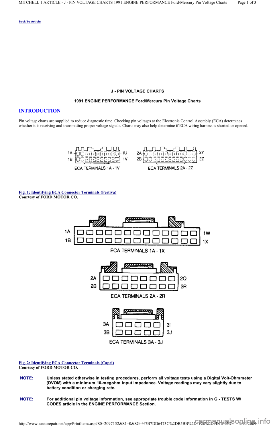
Pin voltage charts are supplied to reduce diagnostic time. Checking pin voltages at the Electronic Control Assembly (ECA) determin es
whether it is receiving and transmitting proper voltage signals. Charts may also help determine if ECA wiring harness is shorted or opened.
Fig. 1: Identifying ECA Connector Terminals (Festiva)
Courtesy of FORD MOTOR CO.
Fig. 2: Identifying ECA Connector Terminals (Capri)
Courtesy of FORD MOTOR CO.
NOTE:Unless stated otherwise in testing procedures, perform all voltage tests using a Digital Volt-Ohm m eter
(DVOM) with a m inim um 10-m egohm input im pedance. Voltage readings m ay vary slightly due to
battery condition or charging rate.
NOTE:For additional pin voltage inform ation, see appropriate trouble code inform ation in G - T EST S W/
CODES article in the ENGINE PERFORMANCE Section.
Page 1 of 3 MITCHELL 1 ARTICLE - J - PIN VOLTAGE CHARTS 1991 ENGINE PERFORMANCE Ford/Mercury Pin Voltage Charts
3/10/2009 http://www.eautorepair.net/app/PrintItems.asp?S0=2097152&S1=0&SG=%7B7DD6473C%2DB5BB%2D4F20%2D9D70%2D
...
Page 143 of 454
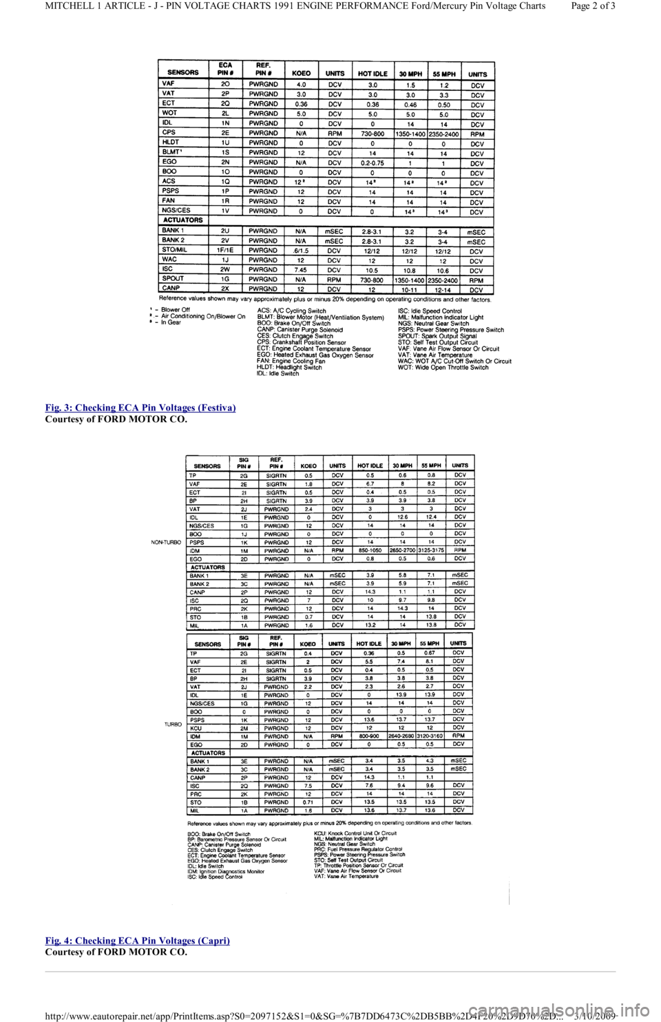
Fig. 3: Checking ECA Pin Voltages (Festiva)
Courtesy of FORD MOTOR CO.
Fig. 4: Checking ECA Pin Voltages (Capri)
Courtesy of FORD MOTOR CO.
Page 2 of 3 MITCHELL 1 ARTICLE - J - PIN VOLTAGE CHARTS 1991 ENGINE PERFORMANCE Ford/Mercury Pin Voltage Charts
3/10/2009 http://www.eautorepair.net/app/PrintItems.asp?S0=2097152&S1=0&SG=%7B7DD6473C%2DB5BB%2D4F20%2D9D70%2D
...
Page 144 of 454

Copyr ight 2009 Mitchell Repair Information Company, LLC. All Rights Reserved.
Article GUID: A00022701
Page 3 of 3 MITCHELL 1 ARTICLE - J - PIN VOLTAGE CHARTS 1991 ENGINE PERFORMANCE Ford/Mercury Pin Voltage Charts
3/10/2009 http://www.eautorepair.net/app/PrintItems.asp?S0=2097152&S1=0&SG=%7B7DD6473C%2DB5BB%2D4F20%2D9D70%2D
...
Page 145 of 454
Back To Article
N - REMOVE/INST ALL/OVERHAUL
1991 ENGINE PERFORMANCE Ford/Mercury Rem oval, Overhaul & Installation
INTRODUCTION
Removal, overhaul and installation procedures are covered in this article. If component removal and installation is primarily an unbolt and
bolt-on procedure, only a torque specification may be furnished.
IGNITION SYSTEM
DISTRIBUTOR
Removal
Disconnect negative battery cable. On Capri, disconnect vacuum hose from vacuum control unit. Disconnect coil wire from distributor cap.
Remove screws and distributor cap. Disconnect electrical connectors. Mark position of distributor housing to cylinder head for reassembly.
Remove distributor mounting bolts and distributor.
Installation
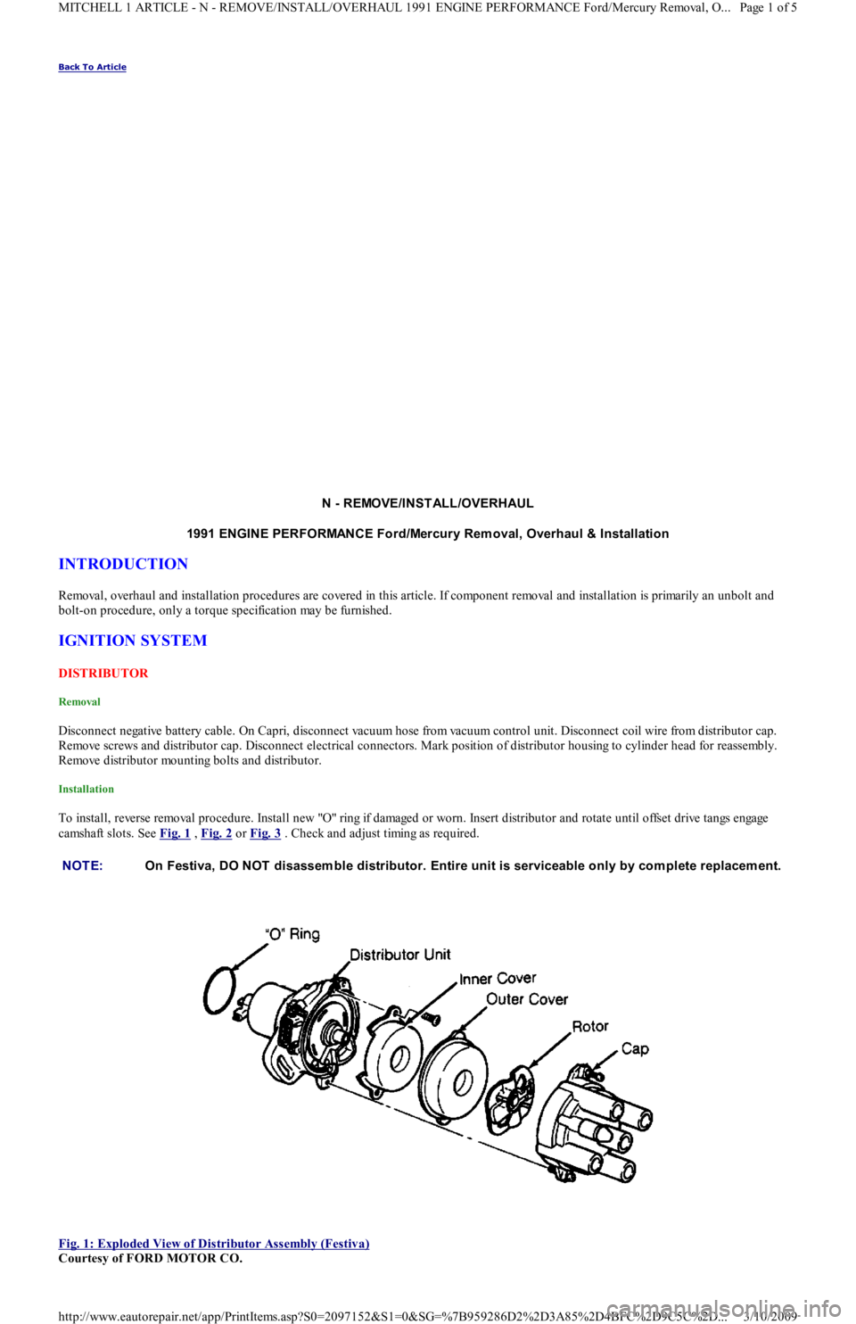
To install, reverse removal procedure. Install new "O" ring if damaged or worn. Insert distributor and rotate until offset drive tangs engage
camshaft slots. See Fig. 1
, Fig. 2 or Fig. 3 . Check and adjust timing as required.
Fig. 1: Exploded View of Distributor Assembly (Festiva)
Courtesy of FORD MOTOR CO. NOTE:On Festiva, DO NOT disassem ble distributor. Entire unit is serviceable only by com plete replacem ent.
Page 1 of 5 MITCHELL 1 ARTICLE - N - REMOVE/INSTALL/OVERHAUL 1991 ENGINE PERFORMANCE Ford/Mercury Removal, O
...
3/10/2009 http://www.eautorepair.net/app/PrintItems.asp?S0=2097152&S1=0&SG=%7B959286D2%2D3A85%2D4BFC%2D9C5C%2D
...
Page 146 of 454
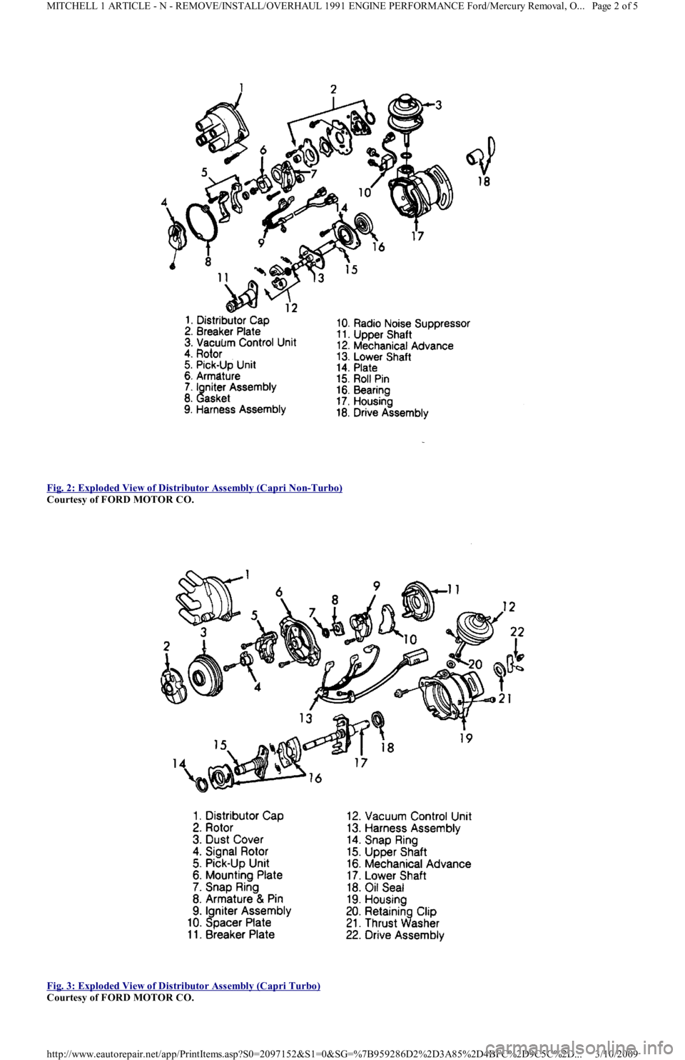
Fig. 2: Exploded View of Distributor Assembly (Capri Non
-Turbo)
Courtesy of FORD MOTOR CO.
Fig. 3: Exploded View of Distributor Assembly (Capri Turbo)
Courtesy of FORD MOTOR CO.
Page 2 of 5 MITCHELL 1 ARTICLE - N - REMOVE/INSTALL/OVERHAUL 1991 ENGINE PERFORMANCE Ford/Mercury Removal, O
...
3/10/2009 http://www.eautorepair.net/app/PrintItems.asp?S0=2097152&S1=0&SG=%7B959286D2%2D3A85%2D4BFC%2D9C5C%2D
...
Page 147 of 454
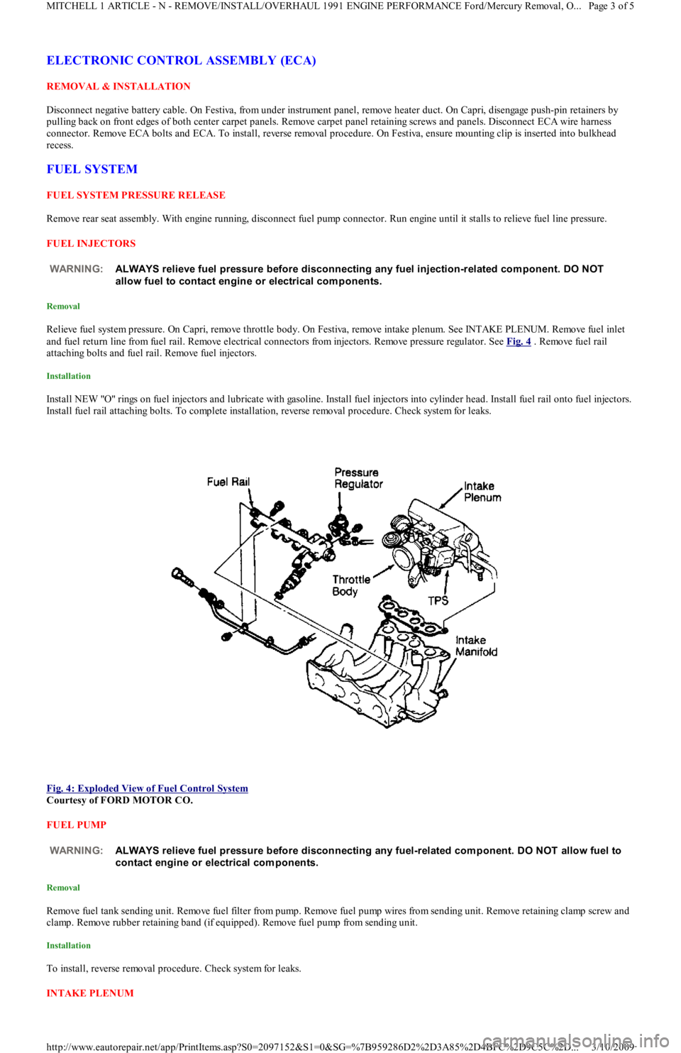
ELECTRONIC CONTROL ASSEMBLY (ECA)
REMOVAL & INSTALLATION
Disconnect negative battery cable. On Festiva, from under instrument panel, remove heater duct. On Capri, disengage push-pin retainers by
pulling back on front edges of both center carpet panels. Remove carpet panel retaining screws and panels. Disconnect ECA wire harness
connector. Remove ECA bolts and ECA. To install, reverse removal procedure. On Festiva, ensure mounting clip is inserted into bulkhead
recess.
FUEL SYSTEM
FUEL SYSTEM PRESSURE RELEASE
Remove rear seat assembly. With engine running, disconnect fuel pump connector. Run engine until it stalls to relieve fuel line pressure.
FUEL INJECTORS
Removal
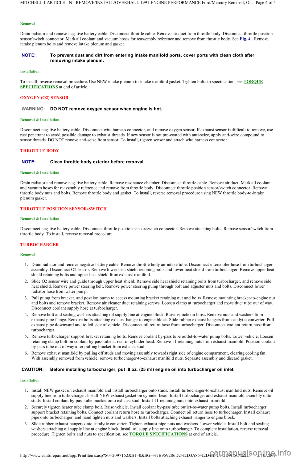
Relieve fuel system pressure. On Capri, remove throttle body. On Festiva, remove intake plenum. See INTAKE PLENUM. Remove fuel inlet
and fuel return line from fuel rail. Remove electrical connectors from injectors. Remove pressure regulator. See Fig. 4
. Remove fuel rail
attaching bolts and fuel rail. Remove fuel injectors.
Installation
Install NEW "O" rings on fuel injectors and lubricate with gasoline. Install fuel injectors into cylinder head. Install fuel rail onto fuel injectors.
Install fuel rail attaching bolts. To complete installation, reverse removal procedure. Check system for leaks.
Fig. 4: Exploded View of Fuel Control System
Courtesy of FORD MOTOR CO.
FUEL PUMP
Removal
Remove fuel tank sending unit. Remove fuel filter from pump. Remove fuel pump wires from sending unit. Remove retaining clamp screw and
clamp. Remove rubber retaining band (if equipped). Remove fuel pump from sending unit.
Installation
To install, reverse removal procedure. Check system for leaks.
INTAKE PLENUM WARNING:ALWAYS relieve fuel pressure before disconnecting any fuel injection-related com ponent. DO NOT
allow fuel to contact engine or electrical com ponents.
WARNING:ALWAYS relieve fuel pressure before disconnecting any fuel-related com ponent. DO NOT allow fuel to
contact engine or electrical com ponents.
Page 3 of 5 MITCHELL 1 ARTICLE - N - REMOVE/INSTALL/OVERHAUL 1991 ENGINE PERFORMANCE Ford/Mercury Removal, O
...
3/10/2009 http://www.eautorepair.net/app/PrintItems.asp?S0=2097152&S1=0&SG=%7B959286D2%2D3A85%2D4BFC%2D9C5C%2D
...
Page 148 of 454
Removal
Drain radiator and remove negative battery cable. Disconnect throttle cable. Remove air duct from throttle body. Disconnect throttle position
sensor/switch connector. Mark all coolant and vacuum hoses for reassembly reference and remove from throttle body. See Fig. 4
. Remove
intake plenum bolts and remove intake plenum and gasket.
Installation
To install, reverse removal procedure. Use NEW intake plenum-to-intake manifold gasket. Tighten bolts to specification, see TORQUE
SPECIFICATIONS at end of article.
OXYGEN (O2) SENSOR
Removal & Installation
Disconnect negative battery cable. Disconnect wire harness connector, and remove oxygen sensor. If exhaust sensor is difficult to remove, use
rust penetrant to avoid possible damage to exhaust threads. If new sensor is not pre-coated with anti-seize, apply anti-seize compound to
sensor threads. DO NOT remove anti-seize from sensor. To install, tighten sensor and attach wire harness connector.
THROTTLE BODY
Removal & Installation
Drain radiator and remove negative battery cable. Remove resonance chamber. Disconnect throttle cable. Remove air duct. Mark all coolant
and vacuum hoses for reassembly reference and remove from throttle body. Disconnect throttle position sensor/switch connector. Remove
throttle body nuts and bolts. Remove throttle body and gasket. To install, reverse removal procedure using NEW throttle body-to-intake
plenum gasket.
THROTTLE POSITION SENSOR/SWITCH
Removal & Installation
Disconnect negative battery cable. Disconnect throttle position sensor/switch connector. Remove attaching bolts. Remove sensor/switch from
throttle body. To install, reverse removal procedure.
TURBOCHARGER
Removal
1. Drain radiator and remove negative battery cable. Remove throttle body air intake tube. Disconnect intercooler hose from turbocharger
assembly. Disconnect O2 sensor. Remove lower heat shield retaining bolts and lower heat shield from turbocharger. Remove upper heat
shield retaining bolts and upper heat shield from exhaust manifold.
2. Slide O2 sensor wire and guide through upper heat shield. Remove side heat shield retaining bolts from turbocharger, and remove sid e
heat shield. Remove power steering belt. Remove power steering pump through bolt and adjuster nuts and bolts. Disconnect lower
radiator hose from water pump.
3. Pull pump from bracket, and position pump to access mounting bracket retaining nut and bolts. Remove mounting bracket-to-engine nut
and bolts and remove bracket. Remove air cleaner duct retaining screws. Loosen clamp at turbocharger and move duct tube out of way.
Disconnect coolant supply hose at turbocharger.
4. Remove bolt and sealing washers attaching oil supply line at engine block. Raise vehicle on hoist. Remove nuts and washers from
exhaust pipe flange. Remove bolts attaching exhaust hanger to engine block. Slide rubber exhaust hangers from catalytic converter. Pull
exhaust pipe downward and to left side of vehicle. Disconnect oil return hose from turbocharger. Disconnect coolant return hose fro m
turbocharger.
5. Remove turbocharger support bracket retaining bolts. Remove coolant by-pass tube outlet-to-water pump bolts. Lower vehicle. Loosen
retaining clamp bolt on coolant by-pass tube at rear of cylinder head. Remove 11 retaining nuts from exhaust manifold. Position coolant
by-pass tube out of way after pulling bracket from exhaust stud.
6. Remove exhaust manifold by pulling off studs and moving assembly towards right side of engine compartment, clearing cooling fan.
With assembly removed from vehicle, remove turbocharger-to-exhaust manifold nuts. Separate assembly and discard gasket.
Installation
1. Install NEW gasket on exhaust manifold and install turbocharger onto studs. Install turbocharger-to-exhaust manifold nuts. Remo ve o il
supply line from turbocharger. Install NEW exhaust gasket on cylinder head. Install turbocharger and exhaust manifold assembly onto
studs. Install coolant by-pass tube bracket onto exhaust stud. Install 11 retaining nuts onto exhaust manifold.
2. Securely tighten heater tube clamp bolt. Raise vehicle. Install coolant by-pass tube outlet-to-water pump bolts. Install turbocharger
support bracket retaining bolts. Connect coolant return hose to turbocharger. Connect oil return hose to turbocharger. Install exhaust
pipe onto turbocharger, and hand tighten nuts and washers. Install bolts attaching exhaust hanger to engine block.
3. Slide rubber exhaust hangers onto catalytic converter. Tighten exhaust pipe nuts and washers. Lower vehicle. Install bolt and sealing
washers attaching oil supply line at engine block. Install oil supply line onto turbocharger. To complete installation, reverse removal
procedure. Tighten bolts and nuts to specification, see TORQUE SPECIFICATIONS
at end of article. NOTE:T o prevent dust and dirt from entering intake m anifold ports, cover ports with clean cloth after
rem oving intake plenum .
WARNING:DO NOT rem ove oxygen sensor when engine is hot.
NOTE:Clean throttle body exterior before rem oval.
CAUT ION: Before installing turbocharger, put .8 oz. (25 m l) engine oil into turbocharger oil inlet.
Page 4 of 5 MITCHELL 1 ARTICLE - N - REMOVE/INSTALL/OVERHAUL 1991 ENGINE PERFORMANCE Ford/Mercury Removal, O
...
3/10/2009 http://www.eautorepair.net/app/PrintItems.asp?S0=2097152&S1=0&SG=%7B959286D2%2D3A85%2D4BFC%2D9C5C%2D
...
Page 149 of 454
VANE AIRFLOW (VAF) METER
Removal
1. Disconnect negative battery cable. On Capri, disconnect primary and secondary wires from coil. On Festiva, disconnect VAF wire
harness connector. Remove air duct.
2. On Capri, remove retaining bolt and ground wire from air cleaner cover. Remove air cleaner cover bolts and air cleaner cover. From
inside of air cleaner cover, remove VAF meter retaining nuts. On Festiva, remove attaching bolt and 4 nuts. Remove vane airflow met er.
Installation
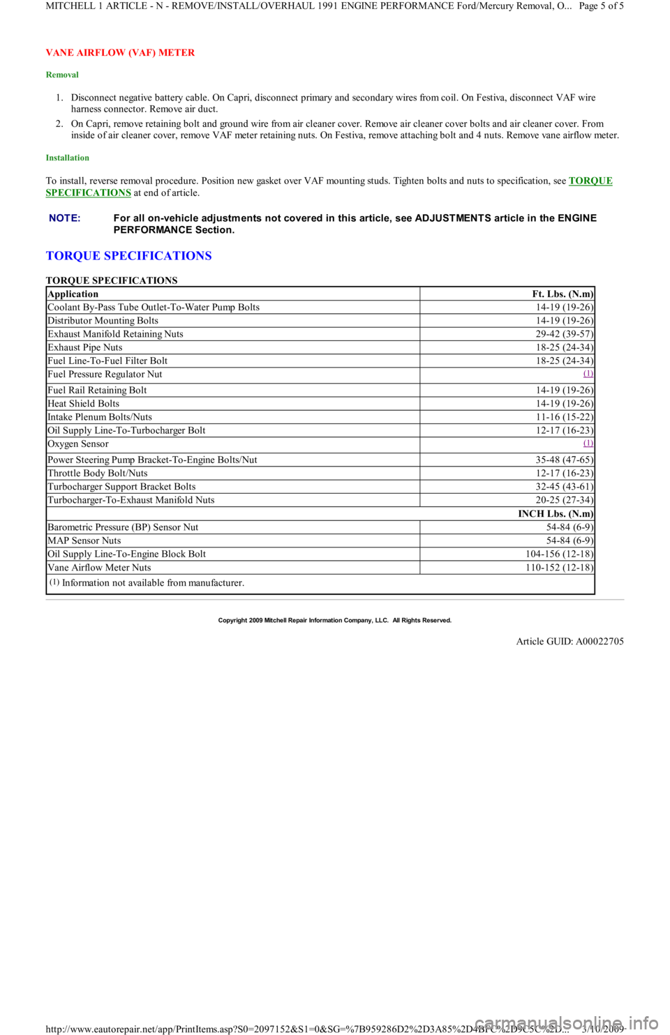
To install, reverse removal procedure. Position new gasket over VAF mounting studs. Tighten bolts and nuts to specification, see TORQUE
SPECIFICATIONS at end of article.
TORQUE SPECIFICATIONS
TORQUE SPECIFICATIONS NOTE:For all on-vehicle adjustm ents not covered in this article, see ADJUST MENT S article in the ENGINE
PERFORMANCE Section.
ApplicationFt. Lbs. (N.m)
Coolant By-Pass Tube Outlet-To-Water Pump Bolts14-19 (19-26)
Distributor Mounting Bolts14-19 (19-26)
Exhaust Manifold Retaining Nuts29-42 (39-57)
Exhaust Pipe Nuts18-25 (24-34)
Fuel Line-To-Fuel Filter Bolt18-25 (24-34)
Fuel Pressure Regulator Nut(1)
Fuel Rail Retaining Bolt14-19 (19-26)
Heat Shield Bolts14-19 (19-26)
Intake Plenum Bolts/Nuts11-16 (15-22)
Oil Supply Line-To-Turbocharger Bolt12-17 (16-23)
Oxygen Sensor(1)
Power Steering Pump Bracket-To-Engine Bolts/Nut35-48 (47-65)
Throttle Body Bolt/Nuts12-17 (16-23)
Turbocharger Support Bracket Bolts32-45 (43-61)
Turbocharger-To-Exhaust Manifold Nuts20-25 (27-34)
INCH Lbs. (N.m)
Barometric Pressure (BP) Sensor Nut54-84 (6-9)
MAP Sensor Nuts54-84 (6-9)
Oil Supply Line-To-Engine Block Bolt104-156 (12-18)
Vane Airflow Meter Nuts110-152 (12-18)
(1)Information not available from manufacturer.
Copyr ight 2009 Mitchell Repair Information Company, LLC. All Rights Reserved.
Article GUID: A00022705
Page 5 of 5 MITCHELL 1 ARTICLE - N - REMOVE/INSTALL/OVERHAUL 1991 ENGINE PERFORMANCE Ford/Mercury Removal, O
...
3/10/2009 http://www.eautorepair.net/app/PrintItems.asp?S0=2097152&S1=0&SG=%7B959286D2%2D3A85%2D4BFC%2D9C5C%2D
...
Page 150 of 454
Back To Article
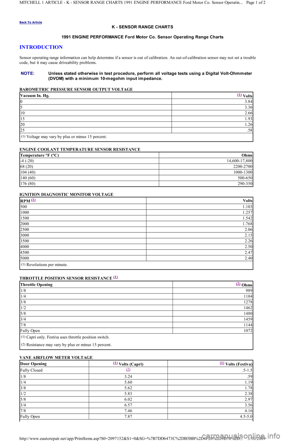
K - SENSOR RANGE CHART S
1991 ENGINE PERFORMANCE Ford Motor Co. Sensor Operating Range Charts
INTRODUCTION
Sensor operating range information can help determine if a sensor is out of calibration. An out-of-calibration sensor may not set a trouble
code, but it may cause driveability problems.
BAROMETRIC PRESSURE SENSOR OUTPUT VOLTAGE
ENGINE COOLANT TEMPERATURE SENSOR RESISTANCE
IGNITION DIAGNOSTIC MONITOR VOLTAGE
THROTTLE POSITION SENSOR RESISTANCE
(1)
VANE AIRFLOW METER VOLTAGE NOTE:Unless stated otherwise in test procedure, perform all voltage tests using a Digital Volt-Ohm m eter
(DVOM) with a m inim um 10-m egohm input im pedance.
Vacuum In. Hg.(1) Volts
03.84
53.36
102.66
151.93
201.26
25.58
(1)Voltage may vary by plus or minus 15 percent.
Temperature °F (°C)Ohms
-4 (-20)14,600-17,800
68 (20)2200-2700
104 (40)1000-1300
140 (60)500-650
176 (80)290-350
RPM (1) Volts
5001.103
10001.257
15001.542
20001.768
25002.06
30002.15
35002.26
40002.50
45002.47
50002.40
(1)Revolutions per minute.
Throttle Opening(2) Ohms
1/8989
1/41104
3/81278
1/21462
5/81480
3/41459
7/81144
Fully Open1072
(1)Capri only. Festiva uses throttle position switch.
(2)Resistance may vary by plus or minus 15 percent.
Door Opening(1) Volts (Capri)(1) Volts (Festiva)
Fully Closed(2) .5-1.5
1/83.24.59
1/45.601.19
3/85.621.78
1/25.832.38
5/86.022.97
3/46.573.56
7/87.464.16
Fully Open7.874.5-5.0
Page 1 of 2 MITCHELL 1 ARTICLE - K - SENSOR RANGE CHARTS 1991 ENGINE PERFORMANCE Ford Motor Co. Sensor Operatin
...
3/10/2009 http://www.eautorepair.net/app/PrintItems.asp?S0=2097152&S1=0&SG=%7B7DD6473C%2DB5BB%2D4F20%2D9D70%2D
...