FORD FESTIVA 1991 Service Manual
Manufacturer: FORD, Model Year: 1991, Model line: FESTIVA, Model: FORD FESTIVA 1991Pages: 454, PDF Size: 9.53 MB
Page 171 of 454
CLEARING CODES
Clearing Codes Procedure
Disconnect negative battery cable. Press brake pedal for 5-10 seconds. Turn off VOM or Super Star II tester. Reconnect battery.
ECA LOCATION
ECA is located on center console behind kick panel on Capri, and under instrument panel on driver side of Festiva.
QUICK TESTS
KEY ON, ENGINE OFF (KOEO) SELF-TEST
KOEO
1. This is a test of electronic engine control system, conducted with power (voltage) applied and engine not running. Activate self-test, and
record all codes displayed.
2. Erase codes, and repeat self-test. Diagnose only codes occurring during repeat self-test. See TROUBLE CODE DEFINITION
table. If
no codes are present, proceed to KEY ON, ENGINE RUNNING (KOER) SELF
-TEST .
KEY ON, ENGINE RUNNING (KOER) SELF-TEST
KOER
1. Deactivate self-test. Start and run engine at 2000 RPM for 2 minutes to warm up EGO sensor. Turn off engine and wait 10 seconds.
2. Restart engine, and activate self-test. Record all service codes displayed. See TROUBLE CODE DEFINITION
table. If no codes are
present, proceed to SWITCH MONITOR TEST
.
SWITCH MONITOR TEST
This test procedure checks input signals received by ECA from individual switches. Use following procedure to perform switch monitor test:
Turn engine off and allow it to cool.
Ensure all accessories are turned off.
Deactivate self-test.
Ensure transmission is in Neutral or Park.
Turn ignition on.
SUPER STAR II Tester
Connect Super Star II tester adapter cable. Turn on tester. Latch center button. Operate each switch listed in SWITCH MONITOR TEST
table. Note output of LED on adapter cable as each switch operates. Record test results.
VOM
1. Ground STI connector. Connect VOM positive lead to SML terminal on self-test connector. Connect negative lead to ground. See Fig.
1 .
2. Operate each switch listed in SWITCH MONITOR TEST
table. Note output on VOM as each switch is operated. Go to specified
PINPOINT TEST if any switch does not meet specification.
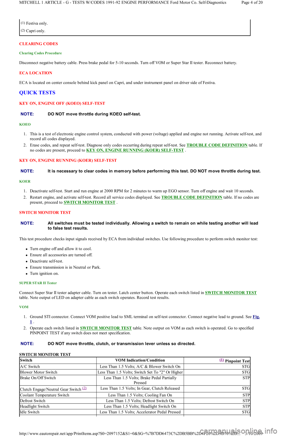
SWITCH MONITOR TEST
(1)Festiva only.
(2)Capri only.
NOTE:DO NOT m ove throttle during KOEO self-test.
NOTE:It is necessary to clear codes in m em ory before perform ing this test. DO NOT m ove throttle during test.
NOTE:All switches m ust be tested individually. Allowing a switch to rem ain on while testing another will lead
to false test results.
NOTE:DO NOT m ove throttle, clutch, or transm ission lever unless so directed.
SwitchVOM Indication/Condition(1) Pinpoint Test
A/C SwitchLess Than 1.5 Volts; A/C & Blower Switch OnSTG
Blower Motor SwitchLess Than 1.5 Volts; Switch Set To "2" Or HigherSTG
Brake On/Off SwitchLess Than 1.5 Volts; Brake Pedal Partially
PressedSTP
Clutch Engage/Neutral Gear Switch (2) Less Than 1.5 Volts; In Gear, Clutch ReleasedSTG
Coolant Temperature SwitchLess Than 1.5 Volts; Cooling Fan OnSTP
Defrost SwitchLess Than 1.5 Volts; Defrost Switch OnSTP
Headlight SwitchLess Than 1.5 Volts; Headlight Switch OnSTP
Id l e Swit chLess Than 1.5 Volts; Accelerator Pedal PressedSTG
Page 4 of 20 MITCHELL 1 ARTICLE - G - TESTS W/CODES 1991-92 ENGINE PERFORMANCE Ford Motor Co. Self-Diagnostics
3/10/2009 http://www.eautorepair.net/app/PrintItems.asp?S0=2097152&S1=0&SG=%7B7DD6473C%2DB5BB%2D4F20%2D9D70%2D
...
Page 172 of 454
WIGGLE TEST
Checking Circuitry
1. Visually inspect suspected sensor, switch, or solenoid. Enter WIGGLE TEST if using Super Star II tester. If using VOM, connect it to
STO terminal on self-test connector, and ground STI self-test connector terminal. Lightly tap sensor, switch, or solenoid.
2. Push and pull on suspected sensor, switch, or solenoid connector, but DO NOT unplug it. Test and wiggle harness vigorously, working
in small sections, from suspected device toward dash panel, and from dash panel to ECA.
3. If VOM or Super Star II tester does not display a positive indication of an intermittent defect, carefully disconnect suspected device.
Remove terminals from connector.
4. Inspect terminals at both ends for corrosion, bad crimps, or improperly seated terminals. Reconnect after inspection. Unplug harness
fro m E CA.
5. Inspect ECA and harness connector terminals for corrosion, bad crimps, or improperly seated terminals. If VOM does not indicate any
intermittent defect, reconnect wiring and erase codes.
PINPOINT TESTS
HOW TO USE PINPOINT TESTS
1. DO NOT perform any PINPOINT TEST unless directed by a QUICK TESTS procedure. Ensure all non-EEC related defects are
corrected. Follow each test step in order until defect is found. DO NOT replace any part unless so directed. When more than one service
code exists, start with first code displayed.
2. PINPOINT TESTS require ensuring electrical circuits are okay before replacing sensors or any other components. Always test circuits
for continuity between sensor and ECA. Test all circuits for shorts to power, opens, or shorts to ground. VREF and VPWR circuits
should be tested with KOEO or as specified in PINPOINT TESTS.
3. DO NOT measure voltage or resistance at ECA, or connect any test light unless specified in testing procedure. DO NOT pierce wiring.
Isolate both ends of a circuit and turn key off whenever checking for shorts or continuity, unless otherwise specified.
4. Disconnect solenoids and switches before checking circuit continuity or energizing solenoids.
5. An open is defined as any resistance greater than 10,000 ohms, unless otherwise specified.
6. To help diagnose circuits to ECA, turn ignition off and disconnect ECA harness. Connect BOB between ECA and ECA harness to
perform circuit and pinpoint tests.
PINPOINT TEST IDM - IGNITION DIAGNOSTIC MONITOR
Fig. 3: Identifying IDM Circuit & Connector
IDM CIRCUIT PIN IDENTIFICATION
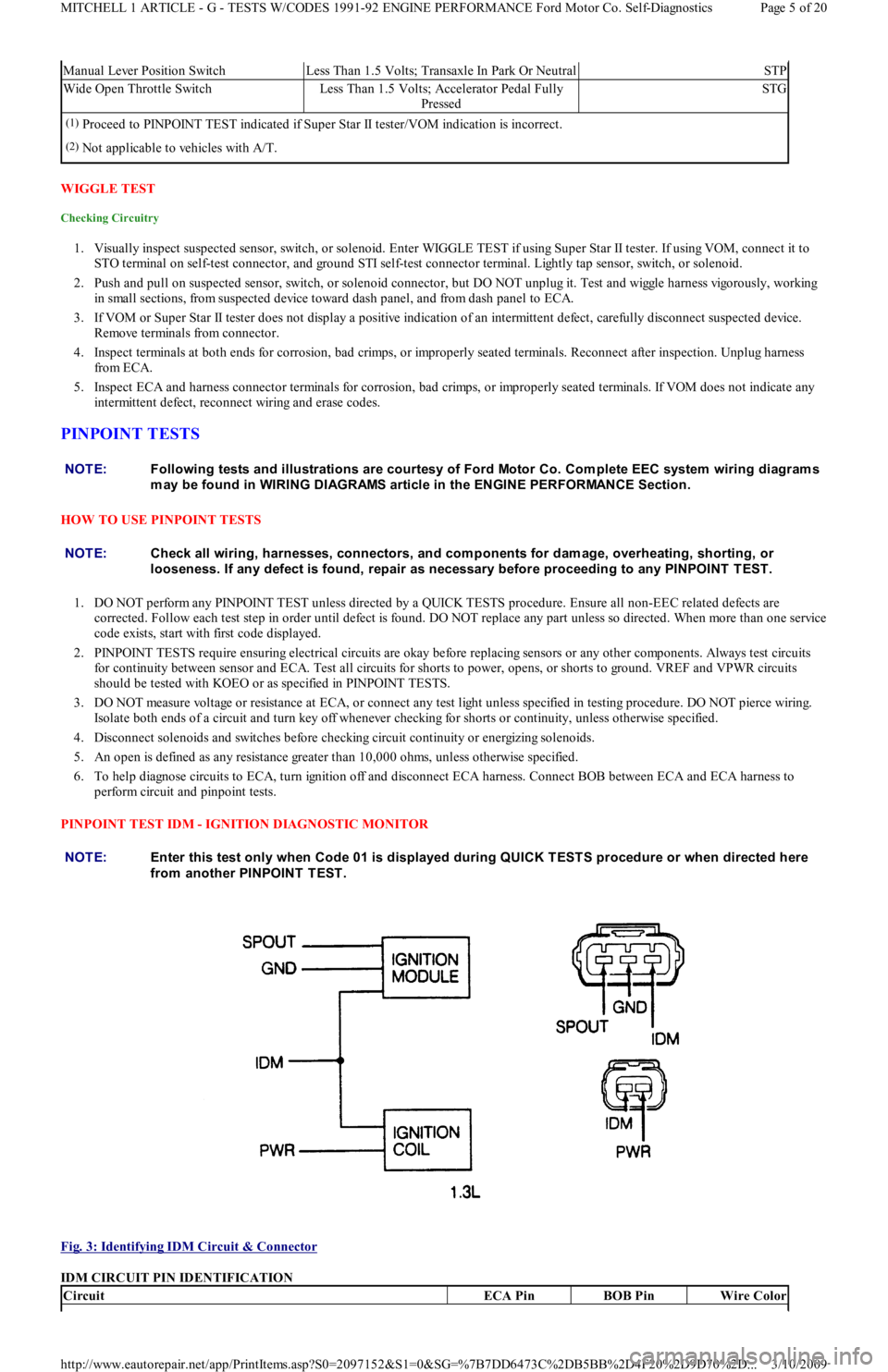
Manual Lever Position SwitchLess Than 1.5 Volts; Transaxle In Park Or NeutralSTP
Wide Open Throttle SwitchLess Than 1.5 Volts; Accelerator Pedal Fully
PressedSTG
(1)Proceed to PINPOINT TEST indicated if Super Star II tester/VOM indication is incorrect.
(2)Not applicable to vehicles with A/T.
NOTE:Following tests and illustrations are courtesy of Ford Motor Co. Com plete EEC system wiring diagram s
m ay be found in WIRING DIAGRAMS article in the ENGINE PERFORMANCE Section.
NOTE:Check all wiring, harnesses, connectors, and com ponents for dam age, overheating, shorting, or
looseness. If any defect is found, repair as necessary before proceeding to any PINPOINT T EST .
NOTE:Enter this test only when Code 01 is displayed during QUICK T EST S procedure or when directed here
from another PINPOINT TEST.
CircuitECA PinBOB PinWire Color
Page 5 of 20 MITCHELL 1 ARTICLE - G - TESTS W/CODES 1991-92 ENGINE PERFORMANCE Ford Motor Co. Self-Diagnostics
3/10/2009 http://www.eautorepair.net/app/PrintItems.asp?S0=2097152&S1=0&SG=%7B7DD6473C%2DB5BB%2D4F20%2D9D70%2D
...
Page 173 of 454
1.3L
1. Connect spark tester between coil secondary wire and ground. Crank engine several times, leaving ignition on between cranking periods.
If continuous sparks jump tester gap, go to next step. If continuous sparks do not jump tester gap, go to step 3).
2. With ignition off, connect BOB, leaving ECA disconnected. Connect test light between test pins IDM and VPWR. Crank engine several
times. If test light flashes each time engine cranks, IDM circuit is okay. Return to QUICK TESTS if directed here from there. If test light
does not flash, repair IDM wire between ECA and coil.
3. Unplug connector from ignition coil. Connect test light between coil IDM wire and PWR wire. Crank engine several times, leaving
ignition on between cranking periods. If test light flashes continuously, go to next step. If test light does not flash continuously, go to
step 6).
4. Turn ignition on. Measure voltage between coil harness PWR wire and ground. If voltage is greater than 10 volts, replace coil. If voltage
is less than 10 volts, repair wire between ignition switch and coil.
5. Connect test light between PWR and ground terminals at coil harness connector. Turn ignition on. If test light glows, replace coil. If test
light does not glow, repair ground wire to coil.
6. Unplug connector from ignition module. Connect jumper wire between SPOUT wire on ignition module harness connector and mating
terminal on ignition module. Connect another jumper wire between ignition module GND wire and mating connector. Leave IDM wire
disconnected. Connect test light between IDM terminal on ignition module and PWR wire. Crank engine several times, leaving ignition
on between cranking periods. If test light flashes each time engine cranks, repair wire between ignition module IDM wire and coil . If t est
light does not flash, go to next step.
7. Turn ignition off. Unplug ignition module connector. Turn ignition on. Measure voltage between ignition module PWR wire and ground.
Turn ignition on. If voltage is not more than 10 volts, repair PWR wire from ignition switch. If voltage is more than 10 volts, go t o n e xt
step.
8. Turn ignition off. Unplug ignition module connector. Turn ignition on. Connect test light between ignition coil PWR wire and ignition
module GND wire. Turn ignition on. If test light glows, go to step 10). If test light does not glow, go to next step.
9. Turn ignition off. Unplug ignition module connector. Connect test light between ignition coil PWR wire and ignition module SPOUT
wire. Crank engine. If test light flashes, check ignition module SPOUT wire for short to ground; if no short exists, replace ignition
module. If test light does not flash, go to next step.
10. Turn ignition off. Unplug ignition module connector. Install BOB, leaving ECA disconnected. Check SPOUT wire for continuity
between BOB test pin and ignition module. If continuity exists, check SPOUT wire for shorts to any other wire. If no short exists,
replace ECA. If continuity does not exist, repair SPOUT wire to ECA.
1.6L
1. Connect spark tester between coil secondary wire and ground. Crank engine several times, leaving ignition on between cranking periods.
If continuous sparks do not jump tester gap, go to step 3). If continuous sparks jump tester gap, go to next step.
2. Turn ignition off. Connect BOB. Leave ECA disconnected. Connect test light between test BOB pins IDM and VPWR. Crank engine
several times. If test light flashes each time engine cranks, IDM circuit is okay. Return to QUICK TESTS if directed here from there. If
test light does not flash, repair IDM wire between ECA and coil.
3. Unplug connector from ignition coil. Connect test light between coil IDM wire and PWR wire. Crank engine several times, leaving
ignition on between cranking periods. If test light does not flash continuously, go to step 6). If test light flashes continuously, go to next
step.
4. Turn ignition on. Measure voltage between coil harness PWR wire and ground. If voltage is greater than 10 volts, replace coil. If voltage
is less than 10 volts, repair wire between ignition switch and coil.
5. Connect test light between PWR and ground terminals at coil harness connector. Turn ignition on. If test light glows, replace coil. If test
light does not glow, repair ground wire to coil.
6. Unplug connector from ignition module. Connect a jumper wire between PWR wire on ignition module harness connector and mating
terminal on ignition module. Leave IDM wire disconnected. Connect test light between IDM terminal on ignition module and PWR
wire. Crank engine several times, leaving ignition on between cranking periods. If test light flashes each time engine cranks, repair wire
between ignition module IDM wire and coil. If test light does not flash. go to next step.
7. Unplug connector from ignition module. Measure voltage between ignition module PWR wire and ground. If voltage is not higher than
10 volts, repair PWR wire from ignition switch. If voltage is higher than 10 volts, go to next step.
8. Turn ignition off. Unplug ignition module connector. Turn ignition on. Connect test light between ignition module PWR wire and
ignition module GND wire. Turn ignition on. If test light glows, replace ignition module. If test light does not glow, repair ignition
module ground wire.
PINPOINT TEST CPS - CRANKSHAFT POSITION SENSOR
1.3L
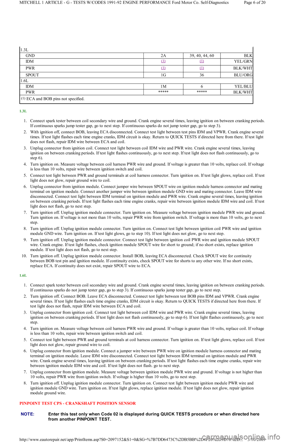
GND2A39, 40, 44, 60BLK
IDM(1) (1) YEL/GRN
PWR(1) (1) BLK/WHT
SPOUT1G36BLU/ORG
1.6L
IDM1M6YEL/BLU
PWR**********BLK/WHT
(1)ECA and BOB pins not specified.
NOTE:Enter this test only when Code 02 is displayed during QUICK T EST S procedure or when directed here
from another PINPOINT TEST.
Page 6 of 20 MITCHELL 1 ARTICLE - G - TESTS W/CODES 1991-92 ENGINE PERFORMANCE Ford Motor Co. Self-Diagnostics
3/10/2009 http://www.eautorepair.net/app/PrintItems.asp?S0=2097152&S1=0&SG=%7B7DD6473C%2DB5BB%2D4F20%2D9D70%2D
...
Page 174 of 454
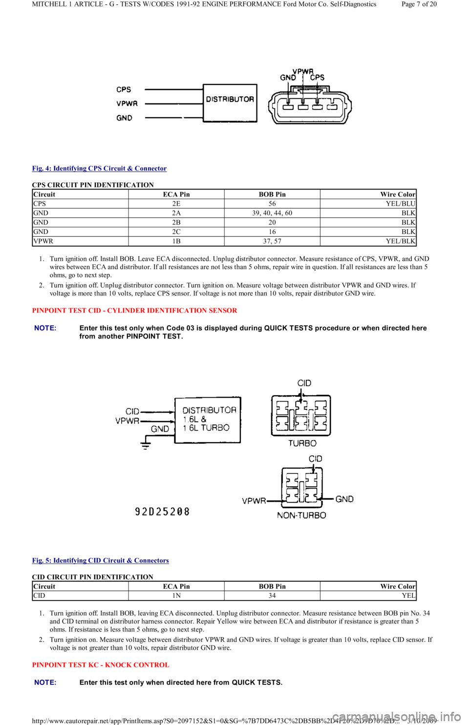
Fig. 4: Identifying CPS Circuit & Connector
CPS CIRCUIT PIN IDENTIFICATION
1. Turn ignition off. Install BOB. Leave ECA disconnected. Unplug distributor connector. Measure resistance of CPS, VPWR, and GND
wires between ECA and distributor. If all resistances are not less than 5 ohms, repair wire in question. If all resistances are less than 5
ohms, go to next step.
2. Turn ignition off. Unplug distributor connector. Turn ignition on. Measure voltage between distributor VPWR and GND wires. If
voltage is more than 10 volts, replace CPS sensor. If voltage is not more than 10 volts, repair distributor GND wire.
PINPOINT TEST CID - CYLINDER IDENTIFICATION SENSOR
Fig. 5: Identifying CID Circuit & Connectors
CID CIRCUIT PIN IDENTIFICATION
1. Turn ignition off. Install BOB, leaving ECA disconnected. Unplug distributor connector. Measure resistance between BOB pin No. 34
and CID terminal on distributor harness connector. Repair Yellow wire between ECA and distributor if resistance is greater than 5
ohms. If resistance is less than 5 ohms, go to next step.
2. Turn ignition on. Measure voltage between distributor VPWR and GND wires. If voltage is greater than 10 volts, replace CID sensor. If
voltage is not greater than 10 volts, repair distributor GND wire.
PINPOINT TEST KC - KNOCK CONTROL
CircuitECA PinBOB PinWire Color
CPS2E56YEL/BLU
GND2A39, 40, 44, 60BLK
GND2B20BLK
GND2C16BLK
VPWR1B37, 57YEL/BLK
NOTE:Enter this test only when Code 03 is displayed during QUICK T EST S procedure or when directed here
from another PINPOINT TEST.
CircuitECA PinBOB PinWire Color
CID1N34YEL
NOTE:Enter this test only when directed here from QUICK T EST S.
Page 7 of 20 MITCHELL 1 ARTICLE - G - TESTS W/CODES 1991-92 ENGINE PERFORMANCE Ford Motor Co. Self-Diagnostics
3/10/2009 http://www.eautorepair.net/app/PrintItems.asp?S0=2097152&S1=0&SG=%7B7DD6473C%2DB5BB%2D4F20%2D9D70%2D
...
Page 175 of 454
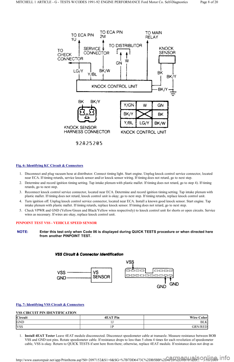
Fig. 6: Identifying KC Circuit & Connectors
1. Disconnect and plug vacuum hose at distributor. Connect timing light. Start engine. Unplug knock control service connector, located
near ECA. If timing retards, service knock sensor and/or knock sensor wiring. If timing does not retard, go to next step.
2. Determine and record ignition timing setting. Tap intake plenum with plastic mallet. If timing does not retard, go to step 4). If t imin g
retards, go to next step.
3. Reconnect knock control service connector, located near ECA. Determine and record ignition timing setting. Tap intake plenum with
plastic mallet. If timing does not retard, knock control unit is okay; go to next step. If timing retards, replace knock control unit.
4. Turn ignition off. Unplug knock control service connector, located near ECA. Install a known good knock sensor. Start engine. Tap
intake plenum with plastic mallet. If timing retards, replace knock sensor. If timing does not retard, go to next step.
5. Check VPWR and GND (Yellow/Green and Black/Yellow wires respectively) to knock control unit for shorts or open circuits. Service
wires as necessary. If wires are okay, replace knock control unit.
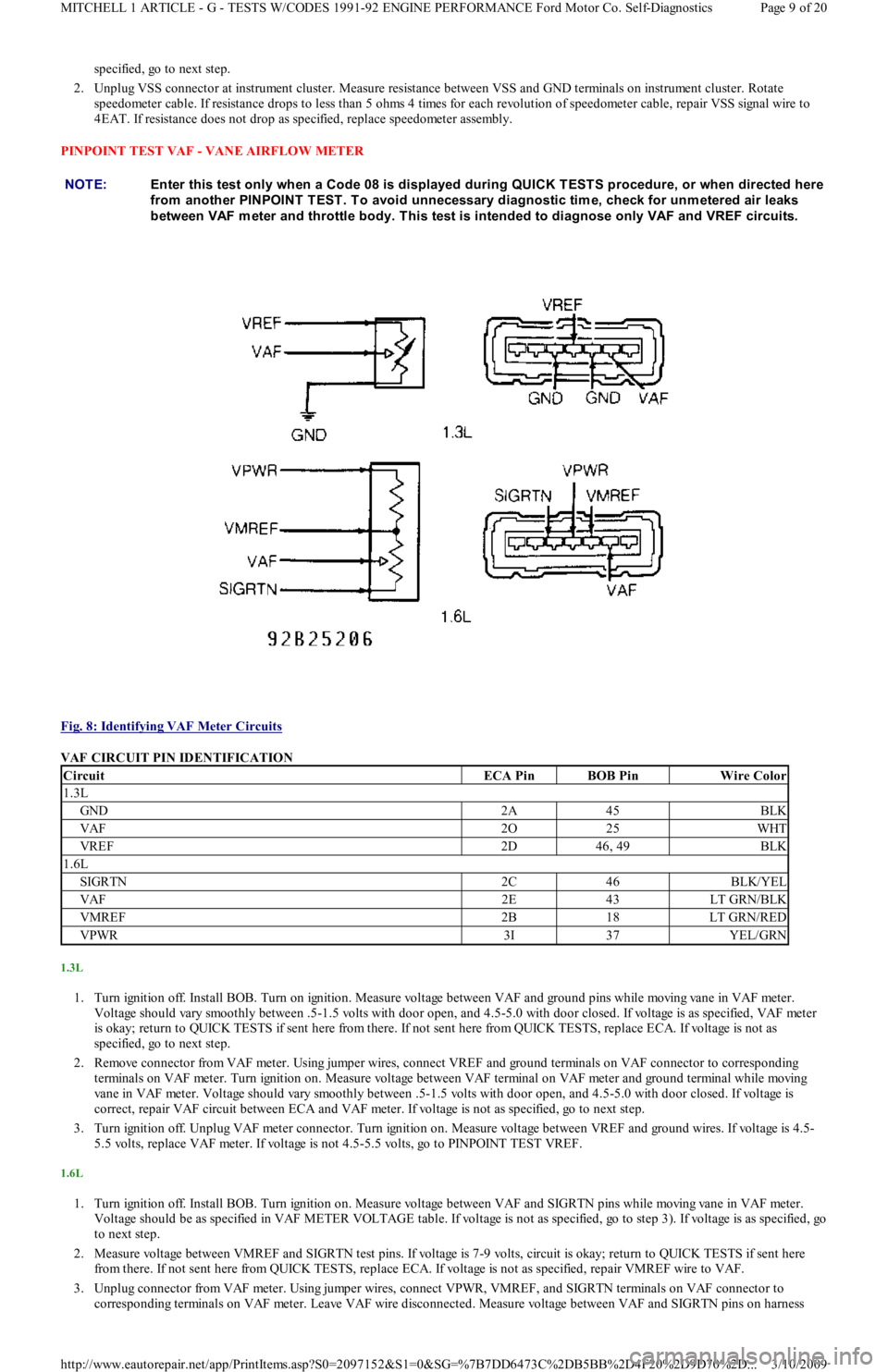
PINPOINT TEST VSS - VEHICLE SPEED SENSOR
Fig. 7: Identifying VSS Circuit & Connectors
VSS CIRCUIT PIN IDENTIFICATION
1.Install 4EAT Tester Leave 4EAT module disconnected. Disconnect speedometer cable at transaxle. Measure resistance between BOB
VSS and GND test pins. Rotate speedometer cable. If resistance drops to less than 5 ohms 4 times for each revolution of speedometer
cable, VSS is okay. Return to QUICK TESTS if sent here from there; otherwise, replace 4EAT module. If resistance does not drop as
NOTE:Enter this test only when Code 06 is displayed during QUICK T EST S procedure or when directed here
from another PINPOINT TEST.
Circuit4EAT PinWire Color
GND1JBLK
VSS1PGRN/RED
Page 8 of 20 MITCHELL 1 ARTICLE - G - TESTS W/CODES 1991-92 ENGINE PERFORMANCE Ford Motor Co. Self-Diagnostics
3/10/2009 http://www.eautorepair.net/app/PrintItems.asp?S0=2097152&S1=0&SG=%7B7DD6473C%2DB5BB%2D4F20%2D9D70%2D
...
Page 176 of 454
specified, go to next step.
2. Unplug VSS connector at instrument cluster. Measure resistance between VSS and GND terminals on instrument cluster. Rotate
speedometer cable. If resistance drops to less than 5 ohms 4 times for each revolution of speedometer cable, repair VSS signal wire to
4EAT. If resistance does not drop as specified, replace speedometer assembly.
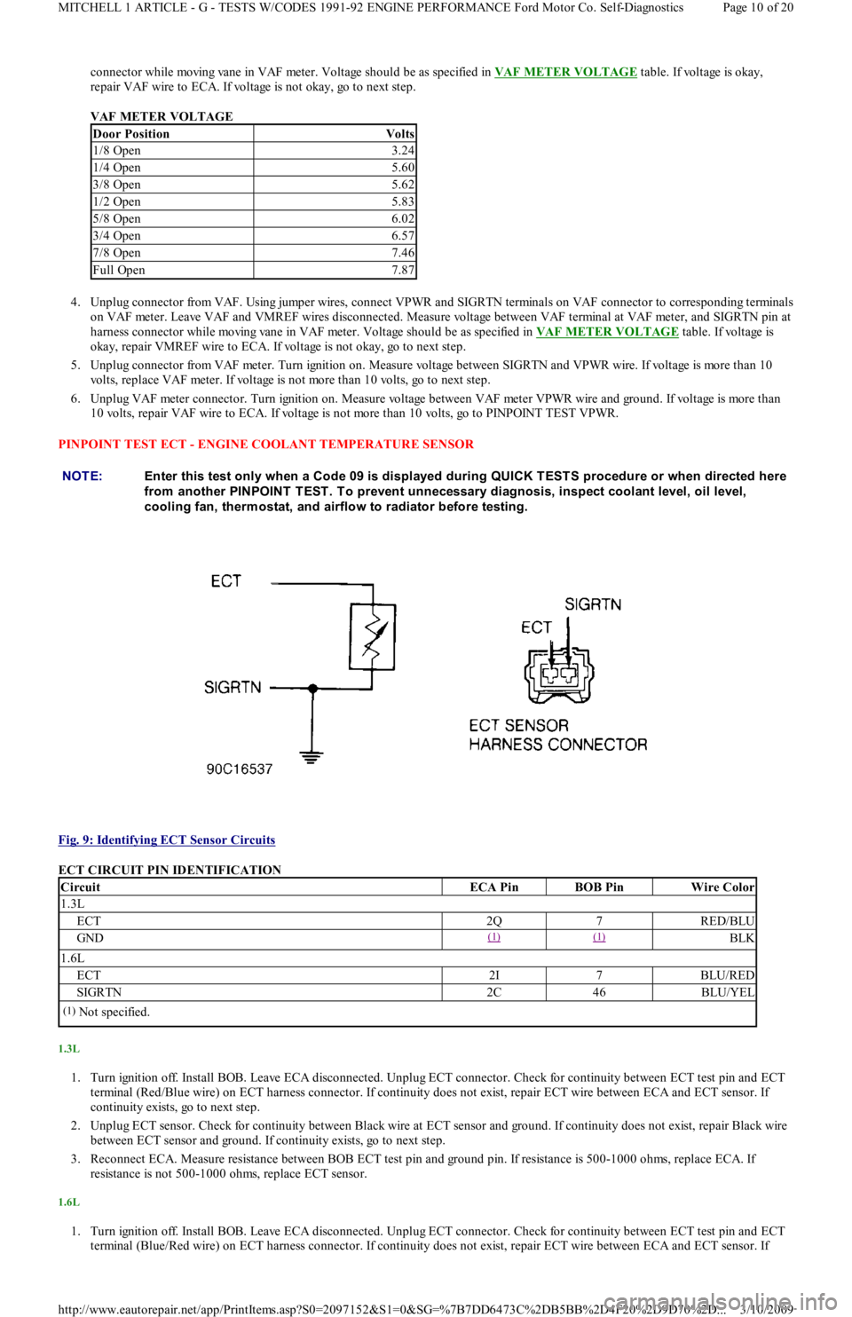
PINPOINT TEST VAF - VANE AIRFLOW METER
Fig. 8: Identifying VAF Meter Circuits
VAF CIRCUIT PIN IDENTIFICATION
1.3L
1. Turn ignition off. Install BOB. Turn on ignition. Measure voltage between VAF and ground pins while moving vane in VAF meter.
Voltage should vary smoothly between .5-1.5 volts with door open, and 4.5-5.0 with door closed. If voltage is as specified, VAF met er
is okay; return to QUICK TESTS if sent here from there. If not sent here from QUICK TESTS, replace ECA. If voltage is not as
specified, go to next step.
2. Remove connector from VAF meter. Using jumper wires, connect VREF and ground terminals on VAF connector to corresponding
terminals on VAF meter. Turn ignition on. Measure voltage between VAF terminal on VAF meter and ground terminal while moving
vane in VAF meter. Voltage should vary smoothly between .5-1.5 volts with door open, and 4.5-5.0 with door closed. If voltage is
correct, repair VAF circuit between ECA and VAF meter. If voltage is not as specified, go to next step.
3. Turn ignition off. Unplug VAF meter connector. Turn ignition on. Measure voltage between VREF and ground wires. If voltage is 4.5-
5.5 volts, replace VAF meter. If voltage is not 4.5-5.5 volts, go to PINPOINT TEST VREF.
1.6L
1. Turn ignition off. Install BOB. Turn ignition on. Measure voltage between VAF and SIGRTN pins while moving vane in VAF meter.
Voltage should be as specified in VAF METER VOLTAGE table. If voltage is not as specified, go to step 3). If voltage is as specified, go
to next step.
2. Measure voltage between VMREF and SIGRTN test pins. If voltage is 7-9 volts, circuit is okay; return to QUICK TESTS if sent here
from there. If not sent here from QUICK TESTS, replace ECA. If voltage is not as specified, repair VMREF wire to VAF.
3. Unplug connector from VAF meter. Using jumper wires, connect VPWR, VMREF, and SIGRTN terminals on VAF connector to
corresponding terminals on VAF meter. Leave VAF wire disconnected. Measure voltage between VAF and SIGRTN pins on harness NOTE:Enter this test only when a Code 08 is displayed during QUICK TESTS procedure, or when directed here
from another PINPOINT T EST . T o avoid unnecessary diagnostic tim e, check for unm etered air leaks
between VAF m eter and throttle body. T his test is intended to diagnose only VAF and VREF circuits.
CircuitECA PinBOB PinWire Color
1.3L
GND2A45BLK
VAF2O25WHT
VREF2D46, 49BLK
1.6L
SIGRTN2C46BLK/YEL
VAF2E43LT GRN/BLK
VMREF2B18LT GRN/RED
VPWR3I37YEL/GRN
Page 9 of 20 MITCHELL 1 ARTICLE - G - TESTS W/CODES 1991-92 ENGINE PERFORMANCE Ford Motor Co. Self-Diagnostics
3/10/2009 http://www.eautorepair.net/app/PrintItems.asp?S0=2097152&S1=0&SG=%7B7DD6473C%2DB5BB%2D4F20%2D9D70%2D
...
Page 177 of 454
connector while moving vane in VAF meter. Voltage should be as specified in VAF METER VOLTAGE table. If voltage is okay,
repair VAF wire to ECA. If voltage is not okay, go to next step.
VAF METER VOLTAGE
4. Unplug connector from VAF. Using jumper wires, connect VPWR and SIGRTN terminals on VAF connector to corresponding terminals
on VAF meter. Leave VAF and VMREF wires disconnected. Measure voltage between VAF terminal at VAF meter, and SIGRTN pin at
harness connector while moving vane in VAF meter. Voltage should be as specified in VAF METER VOLTAGE
table. If voltage is
okay, repair VMREF wire to ECA. If voltage is not okay, go to next step.
5. Unplug connector from VAF meter. Turn ignition on. Measure voltage between SIGRTN and VPWR wire. If voltage is more than 10
volts, replace VAF meter. If voltage is not more than 10 volts, go to next step.
6. Unplug VAF meter connector. Turn ignition on. Measure voltage between VAF meter VPWR wire and ground. If voltage is more than
10 volts, repair VAF wire to ECA. If voltage is not more than 10 volts, go to PINPOINT TEST VPWR.
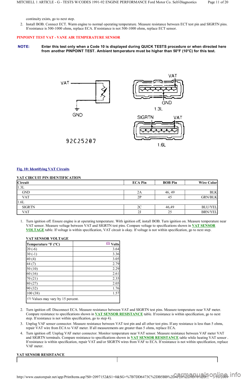
PINPOINT TEST ECT - ENGINE COOLANT TEMPERATURE SENSOR
Fig. 9: Identifying ECT Sensor Circuits
ECT CIRCUIT PIN IDENTIFICATION
1.3L
1. Turn ignition off. Install BOB. Leave ECA disconnected. Unplug ECT connector. Check for continuity between ECT test pin and ECT
terminal (Red/Blue wire) on ECT harness connector. If continuity does not exist, repair ECT wire between ECA and ECT sensor. If
continuity exists, go to next step.
2. Unplug ECT sensor. Check for continuity between Black wire at ECT sensor and ground. If continuity does not exist, repair Black wire
between ECT sensor and ground. If continuity exists, go to next step.
3. Reconnect ECA. Measure resistance between BOB ECT test pin and ground pin. If resistance is 500-1000 ohms, replace ECA. If
resistance is not 500-1000 ohms, replace ECT sensor.
1.6L
1. Turn ignition off. Install BOB. Leave ECA disconnected. Unplug ECT connector. Check for continuity between ECT test pin and ECT
terminal (Blue/Red wire) on ECT harness connector. If continuity does not exist, repair ECT wire between ECA and ECT sensor. If
Door PositionVolts
1/8 Open3.24
1/4 Open5.60
3/8 Open5.62
1/2 Open5.83
5/8 Open6.02
3/4 Open6.57
7/8 Open7.46
Full Open7.87
NOTE:Enter this test only when a Code 09 is displayed during QUICK T EST S procedure or when directed here
from another PINPOINT T EST . T o prevent unnecessary diagnosis, inspect coolant level, oil level,
cooling fan, therm ostat, and airflow to radiator before testing.
CircuitECA PinBOB PinWire Color
1.3L
ECT2Q7RED/BLU
GND(1) (1) BLK
1.6L
ECT2I7BLU/RED
SIGRTN2C46BLU/YEL
(1)Not specified.
Page 10 of 20 MITCHELL 1 ARTICLE - G - TESTS W/CODES 1991-92 ENGINE PERFORMANCE Ford Motor Co. Self-Diagnostics
3/10/2009 http://www.eautorepair.net/app/PrintItems.asp?S0=2097152&S1=0&SG=%7B7DD6473C%2DB5BB%2D4F20%2D9D70%2D
...
Page 178 of 454
continuity exists, go to next step.
2. Install BOB. Connect ECT. Warm engine to normal operating temperature. Measure resistance between ECT test pin and SIGRTN pins.
If resistance is 500-1000 ohms, replace ECA. If resistance is not 500-1000 ohms, replace ECT sensor.
PINPOINT TEST VAT - VANE AIR TEMPERATURE SENSOR
Fig. 10: Identifying VAT Circuits
VAT CIRCUIT PIN IDENTIFICATION
1. Turn ignition off. Ensure engine is at operating temperature. With ignition off, install BOB. Turn ignition on. Measure temperature near
VAT sensor. Measure voltage between VAT and SIGRTN test pins. Compare voltage to specifications shown in VAT SENSOR
VOLTAGE table. If voltage is within specification, VAT circuit is okay. If voltage is not within specification, go to next step.
VAT SENSOR VOLTAGE
2. Turn ignition off. Disconnect ECA. Measure resistance between VAT and SIGRTN test pins. Measure temperature near VAF meter.
Compare resistance to specifications shown in VAT SENSOR RESISTANCE
table. If resistance is within specification, go to next
step. If resistance is not within specification, go to step 4).
3. Unplug VAF sensor connector. Measure resistance between VAT test pin and all other test pins. If any resistance is less than 5 ohms,
repair VAT wire from ECA to VAF meter. If all measurements are greater than 5 ohms, replace ECA.
4. Turn ignition off. Unplug VAF meter connector. Monitor temperature near VAT sensor. Measure resistance between VAF meter VAT
and SIGRTN terminals. Compare resistance to specifications shown in VAT SENSOR RESISTANCE
table while heating VAT sensor .
If resistance is within specification, repair VAT and/or SIGRTN wires from VAF to ECA. If resistance is not within specification, replace
VAF meter.
VAT SENSOR RESISTANCE NOTE:Enter this test only when a Code 10 is displayed during QUICK T EST S procedure or when directed here
from another PINPOINT T EST . Am bient tem perature m ust be higher than 50°F (10°C) for this test.
CircuitECA PinBOB PinWire Color
1.3L
GND2A46, 49BLK
VAT2P45GRN/BLK
1.6L
SIGRTN2C46,49BLU/YEL
VAT2J25BRN/YEL
Temperature °F (°C)(1) Volts
20 (-6)3.64
30 (-1)3.36
40 (4)3.05
44 (7)2.79
50 (10)2.29
60 (16)2.61
70 (21)2.35
80 (27)2.05
90 (32)1.76
100 (38)1.57
(1)Values may vary by 15 percent.
Page 11 of 20 MITCHELL 1 ARTICLE - G - TESTS W/CODES 1991-92 ENGINE PERFORMANCE Ford Motor Co. Self-Diagnostics
3/10/2009 http://www.eautorepair.net/app/PrintItems.asp?S0=2097152&S1=0&SG=%7B7DD6473C%2DB5BB%2D4F20%2D9D70%2D
...
Page 179 of 454
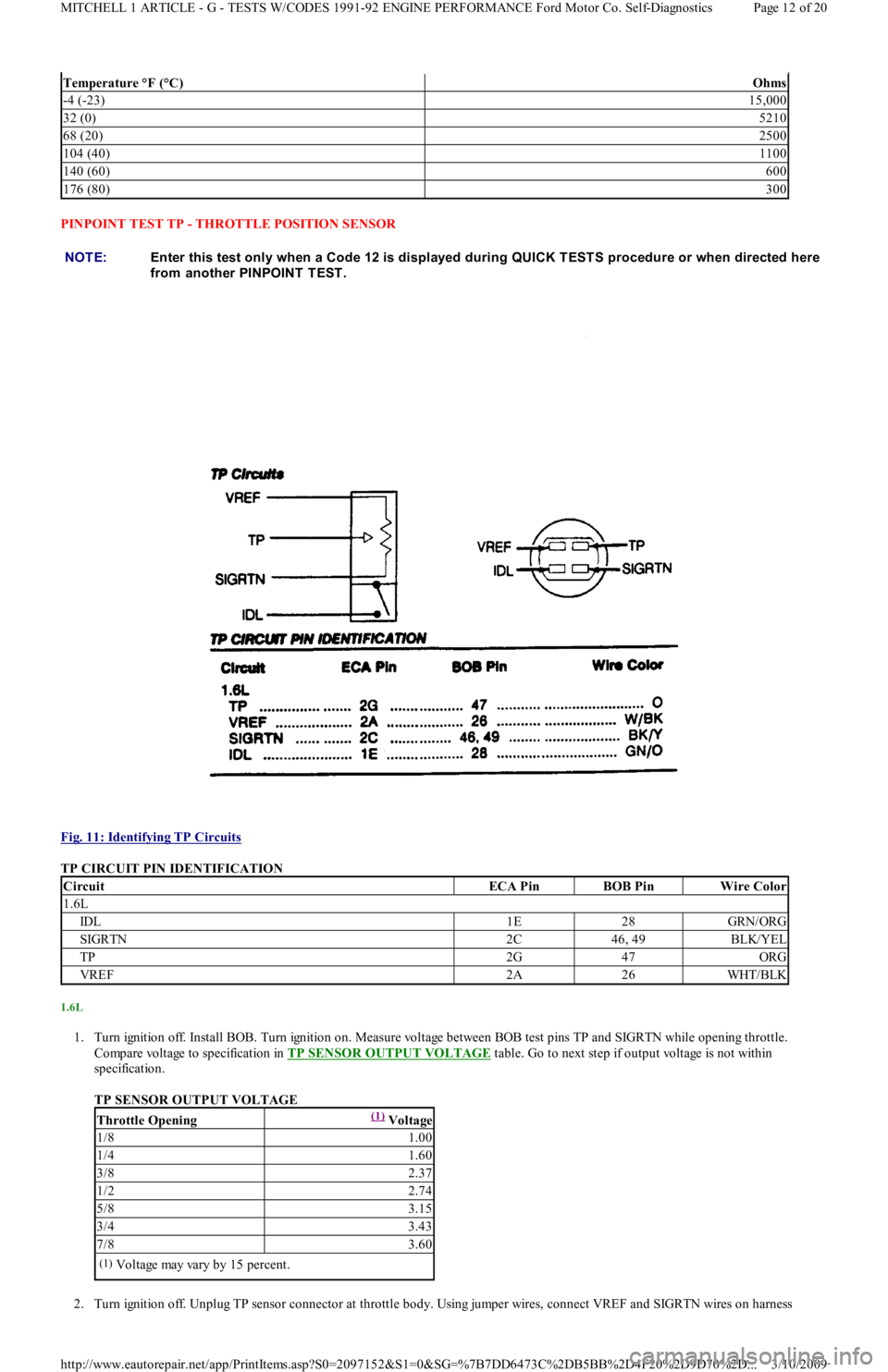
PINPOINT TEST TP - THROTTLE POSITION SENSOR
Fig. 11: Identifying TP Circuits
TP CIRCUIT PIN IDENTIFICATION
1.6L
1. Turn ignition off. Install BOB. Turn ignition on. Measure voltage between BOB test pins TP and SIGRTN while opening throttle.
Compare voltage to specification in TP SENSOR OUTPUT VOLTAGE
table. Go to next step if output voltage is not within
specification.
TP SENSOR OUTPUT VOLTAGE
2. Turn ignition off. Unplug TP sensor connector at throttle body. Using jumper wires, connect VREF and SIGRTN wires on harness
Temperature °F (°C)Ohms
-4 (-23)15,000
32 (0)5210
68 (20)2500
104 (40)1100
140 (60)600
176 (80)300
NOTE:Enter this test only when a Code 12 is displayed during QUICK T EST S procedure or when directed here
from another PINPOINT TEST.
CircuitECA PinBOB PinWire Color
1.6L
IDL1E28GRN/ORG
SIGRTN2C46, 49BLK/YEL
TP2G47ORG
VREF2A26WHT/BLK
Throttle Opening(1) Voltage
1/81.00
1/41.60
3/82.37
1/22.74
5/83.15
3/43.43
7/83.60
(1)Voltage may vary by 15 percent.
Page 12 of 20 MITCHELL 1 ARTICLE - G - TESTS W/CODES 1991-92 ENGINE PERFORMANCE Ford Motor Co. Self-Diagnostics
3/10/2009 http://www.eautorepair.net/app/PrintItems.asp?S0=2097152&S1=0&SG=%7B7DD6473C%2DB5BB%2D4F20%2D9D70%2D
...
Page 180 of 454
connector to corresponding terminals on TP sensor connector. Turn ignition on. Measure voltage between TP and SIGRTN terminals on
TP sensor while opening throttle. Compare voltage to specification in TP SENSOR OUTPUT VOLTAGE
table. If voltage is within
specification, repair TP wire to ECA. Go to next step if voltage is not within specification.
3. Turn ignition off. Unplug TP harness connector. Turn ignition on. Measure voltage between VREF and SIGRTN wires on TP harness
connect-or. If voltage is 4-5 volts, replace TP sensor. If voltage is not 4.5-5.5 volts, go to next step.
4. Measure voltage between VREF wire on TP harness connector and ground. If voltage is 4-5 volts, adjust or replace throttle position
sensor. If voltage is not 4-5 volts, go to PINPOINT TEST VREF
.
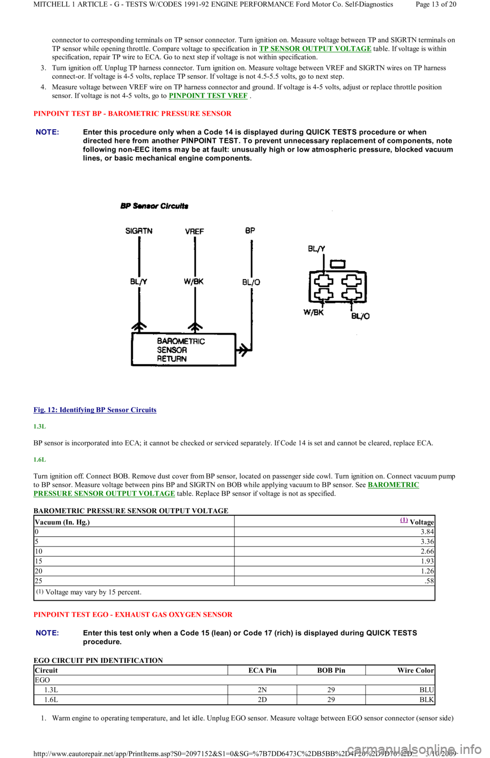
PINPOINT TEST BP - BAROMETRIC PRESSURE SENSOR
Fig. 12: Identifying BP Sensor Circuits
1.3L
BP sensor is incorporated into ECA; it cannot be checked or serviced separately. If Code 14 is set and cannot be cleared, replace ECA.
1.6L
Turn ignition off. Connect BOB. Remove dust cover from BP sensor, located on passenger side cowl. Turn ignition on. Connect vacuum pump
to BP sensor. Measure voltage between pins BP and SIGRTN on BOB while applying vacuum to BP sensor. See BAROMETRIC
PRESSURE SENSOR OUTPUT VOLTAGE table. Replace BP sensor if voltage is not as specified.
BAROMETRIC PRESSURE SENSOR OUTPUT VOLTAGE
PINPOINT TEST EGO - EXHAUST GAS OXYGEN SENSOR
EGO CIRCUIT PIN IDENTIFICATION
1. Warm engine to operating temperature, and let idle. Unplug EGO sensor. Measure voltage between EGO sensor connector (sensor side) NOTE:Enter this procedure only when a Code 14 is displayed during QUICK T EST S procedure or when
directed here from another PINPOINT T EST . T o prevent unnecessary replacem ent of com ponents, note
following non-EEC item s m ay be at fault: unusually high or low atm ospheric pressure, blocked vacuum
lines, or basic m echanical engine com ponents.
Vacuum (In. Hg.)(1) Voltage
03.84
53.36
102.66
151.93
201.26
25.58
(1)Voltage may vary by 15 percent.
NOTE:Enter this test only when a Code 15 (lean) or Code 17 (rich) is displayed during QUICK TESTS
procedure.
CircuitECA PinBOB PinWire Color
EGO
1.3L2N29BLU
1.6L2D29BLK
Page 13 of 20 MITCHELL 1 ARTICLE - G - TESTS W/CODES 1991-92 ENGINE PERFORMANCE Ford Motor Co. Self-Diagnostics
3/10/2009 http://www.eautorepair.net/app/PrintItems.asp?S0=2097152&S1=0&SG=%7B7DD6473C%2DB5BB%2D4F20%2D9D70%2D
...