coolant capacity FORD FESTIVA 1991 Service Manual
[x] Cancel search | Manufacturer: FORD, Model Year: 1991, Model line: FESTIVA, Model: FORD FESTIVA 1991Pages: 454, PDF Size: 9.53 MB
Page 89 of 454

Back To Article
1990-92 ENGINE COOLING
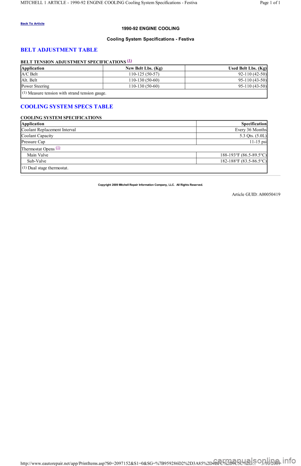
Cooling System Specifications - Festiva
BELT ADJUSTMENT TABLE
BELT TENSION ADJUSTMENT SPECIFICATIONS (1)
COOLING SYSTEM SPECS TABLE
COOLING SYSTEM SPECIFICATIONS
ApplicationNew Belt Lbs. (Kg)Used Belt Lbs. (Kg)
A/C Belt110-125 (50-57)92-110 (42-50)
Alt. Belt110-130 (50-60)95-110 (43-50)
Power Steering110-130 (50-60)95-110 (43-50)
(1)Measure tension with strand tension gauge.
ApplicationSpecification
Coolant Replacement IntervalEvery 36 Months
Coolant Capacity5.3 Qts. (5.0L)
Pressure Cap11-15 psi
Thermostat Opens (1)
Main Valve188-193°F (86.5-89.5°C)
Sub-Valve182-188°F (83.5-86.5°C)
(1)Dual stage thermostat.
Copyr ight 2009 Mitchell Repair Information Company, LLC. All Rights Reserved.
Article GUID: A00050419
Page 1 of 1 MITCHELL 1 ARTICLE - 1990-92 ENGINE COOLING Cooling System Specifications - Festiva
3/10/2009 http://www.eautorepair.net/app/PrintItems.asp?S0=2097152&S1=0&SG=%7B959286D2%2D3A85%2D4BFC%2D9C5C%2D
...
Page 102 of 454

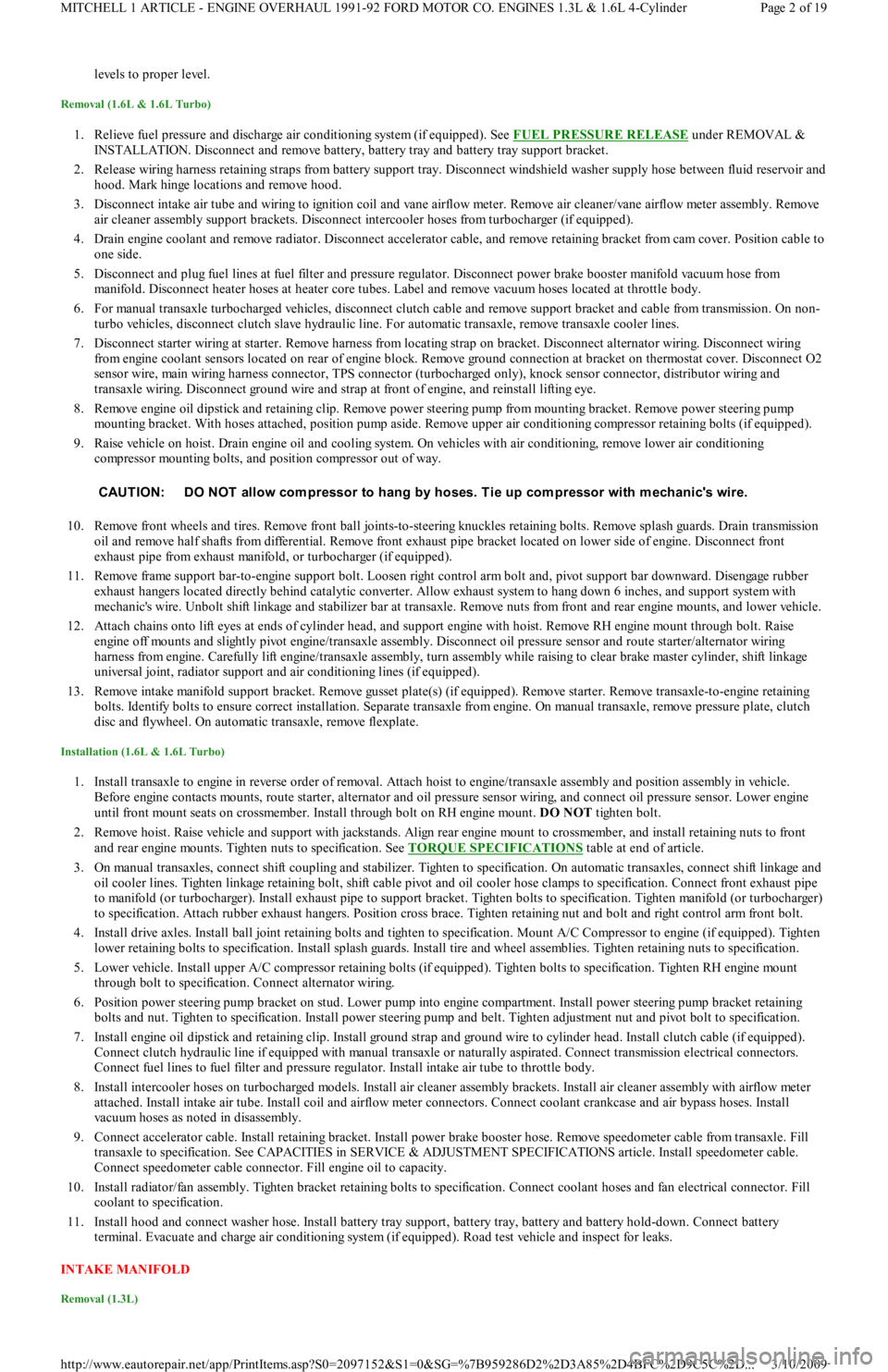
levels to proper level.
Removal (1.6L & 1.6L Turbo)
1. Relieve fuel pressure and discharge air conditioning system (if equipped). See FUEL PRESSURE RELEASE under REMOVAL &
INSTALLATION. Disconnect and remove battery, battery tray and battery tray support bracket.
2. Release wiring harness retaining straps from battery support tray. Disconnect windshield washer supply hose between fluid reservoir and
hood. Mark hinge locations and remove hood.
3. Disconnect intake air tube and wiring to ignition coil and vane airflow meter. Remove air cleaner/vane airflow meter assembly. Remove
air cleaner assembly support brackets. Disconnect intercooler hoses from turbocharger (if equipped).
4. Drain engine coolant and remove radiator. Disconnect accelerator cable, and remove retaining bracket from cam cover. Position cable to
one side.
5. Disconnect and plug fuel lines at fuel filter and pressure regulator. Disconnect power brake booster manifold vacuum hose from
manifold. Disconnect heater hoses at heater core tubes. Label and remove vacuum hoses located at throttle body.
6. For manual transaxle turbocharged vehicles, disconnect clutch cable and remove support bracket and cable from transmission. On non-
turbo vehicles, disconnect clutch slave hydraulic line. For automatic transaxle, remove transaxle cooler lines.
7. Disconnect starter wiring at starter. Remove harness from locating strap on bracket. Disconnect alternator wiring. Disconnect wiring
from engine coolant sensors located on rear of engine block. Remove ground connection at bracket on thermostat cover. Disconnect O2
sensor wire, main wiring harness connector, TPS connector (turbocharged only), knock sensor connector, distributor wiring and
transaxle wiring. Disconnect ground wire and strap at front of engine, and reinstall lifting eye.
8. Remove engine oil dipstick and retaining clip. Remove power steering pump from mounting bracket. Remove power steering pump
mounting bracket. With hoses attached, position pump aside. Remove upper air conditioning compressor retaining bolts (if equipped).
9. Raise vehicle on hoist. Drain engine oil and cooling system. On vehicles with air conditioning, remove lower air conditioning
compressor mounting bolts, and position compressor out of way.
10. Remove front wheels and tires. Remove front ball joints-to-ste e r in g kn u c kl e s r e t a in in g b o l t s. R e mo ve sp l a sh gu a r d s. Dr a in t ransmission
oil and remove half shafts from differential. Remove front exhaust pipe bracket located on lower side of engine. Disconnect front
exhaust pipe from exhaust manifold, or turbocharger (if equipped).
11. Remove frame support bar-to-engine support bolt. Loosen right control arm bolt and, pivot support bar downward. Disengage rubber
exhaust hangers located directly behind catalytic converter. Allow exhaust system to hang down 6 inches, and support system with
mechanic's wire. Unbolt shift linkage and stabilizer bar at transaxle. Remove nuts from front and rear engine mounts, and lower vehicle.
12. Attach chains onto lift eyes at ends of cylinder head, and support engine with hoist. Remove RH engine mount through bolt. Raise
engine off mounts and slightly pivot engine/transaxle assembly. Disconnect oil pressure sensor and route starter/alternator wiring
harness from engine. Carefully lift engine/transaxle assembly, turn assembly while raising to clear brake master cylinder, shift linkage
universal joint, radiator support and air conditioning lines (if equipped).
13. Remove intake manifold support bracket. Remove gusset plate(s) (if equipped). Remove starter. Remove transaxle-to-engine retaining
bolts. Identify bolts to ensure correct installation. Separate transaxle from engine. On manual transaxle, remove pressure plate, clutch
disc and flywheel. On automatic transaxle, remove flexplate.
Installation (1.6L & 1.6L Turbo)
1. Install transaxle to engine in reverse order of removal. Attach hoist to engine/transaxle assembly and position assembly in vehicle.
Before engine contacts mounts, route starter, alternator and oil pressure sensor wiring, and connect oil pressure sensor. Lower engine
until front mount seats on crossmember. Install through bolt on RH engine mount. DO NOT tighten bolt.
2. Remove hoist. Raise vehicle and support with jackstands. Align rear engine mount to crossmember, and install retaining nuts to front
and rear engine mounts. Tighten nuts to specification. See TORQUE SPECIFICATIONS
table at end of article.
3. On manual transaxles, connect shift coupling and stabilizer. Tighten to specification. On automatic transaxles, connect shift linkage and
oil cooler lines. Tighten linkage retaining bolt, shift cable pivot and oil cooler hose clamps to specification. Connect front exhaust pipe
to manifold (or turbocharger). Install exhaust pipe to support bracket. Tighten bolts to specification. Tighten manifold (or turbocharger)
to specification. Attach rubber exhaust hangers. Position cross brace. Tighten retaining nut and bolt and right control arm front bolt.
4. Install drive axles. Install ball joint retaining bolts and tighten to specification. Mount A/C Compressor to engine (if equipped). Tighten
lower retaining bolts to specification. Install splash guards. Install tire and wheel assemblies. Tighten retaining nuts to specification.
5. Lower vehicle. Install upper A/C compressor retaining bolts (if equipped). Tighten bolts to specification. Tighten RH engine mo u n t
through bolt to specification. Connect alternator wiring.
6. Position power steering pump bracket on stud. Lower pump into engine compartment. Install power steering pump bracket retaining
bolts and nut. Tighten to specification. Install power steering pump and belt. Tighten adjustment nut and pivot bolt to specification.
7. Install engine oil dipstick and retaining clip. Install ground strap and ground wire to cylinder head. Install clutch cable (if equipped).
Connect clutch hydraulic line if equipped with manual transaxle or naturally aspirated. Connect transmission electrical connectors.
Connect fuel lines to fuel filter and pressure regulator. Install intake air tube to throttle body.
8. Install intercooler hoses on turbocharged models. Install air cleaner assembly brackets. Install air cleaner assembly with airflow meter
attached. Install intake air tube. Install coil and airflow meter connectors. Connect coolant crankcase and air bypass hoses. Install
vacuum hoses as noted in disassembly.
9. Connect accelerator cable. Install retaining bracket. Install power brake booster hose. Remove speedometer cable from transaxle. Fill
transaxle to specification. See CAPACITIES in SERVICE & ADJUSTMENT SPECIFICATIONS article. Install speedometer cable.
Connect speedometer cable connector. Fill engine oil to capacity.
10. Install radiator/fan assembly. Tighten bracket retaining bolts to specification. Connect coolant hoses and fan electrical connector. Fill
coolant to specification.
11. Install hood and connect washer hose. Install battery tray support, battery tray, battery and battery hold-down. Connect battery
terminal. Evacuate and charge air conditioning system (if equipped). Road test vehicle and inspect for leaks.
INTAKE MANIFOLD
Removal (1.3L)
CAUT ION: DO NOT allow com pressor to hang by hoses. T ie up com pressor with m echanic's wire.
Page 2 of 19 MITCHELL 1 ARTICLE - ENGINE OVERHAUL 1991-92 FORD MOTOR CO. ENGINES 1.3L & 1.6L 4-Cylinder
3/10/2009 http://www.eautorepair.net/app/PrintItems.asp?S0=2097152&S1=0&SG=%7B959286D2%2D3A85%2D4BFC%2D9C5C%2D
...
Page 349 of 454

Back To Article
1991 AIR CONDIT IONING & HEAT
MANUAL A/C
A/C SYSTEM SPECIFICATIONS
SPECIFICATIONS
DESCRIPTION
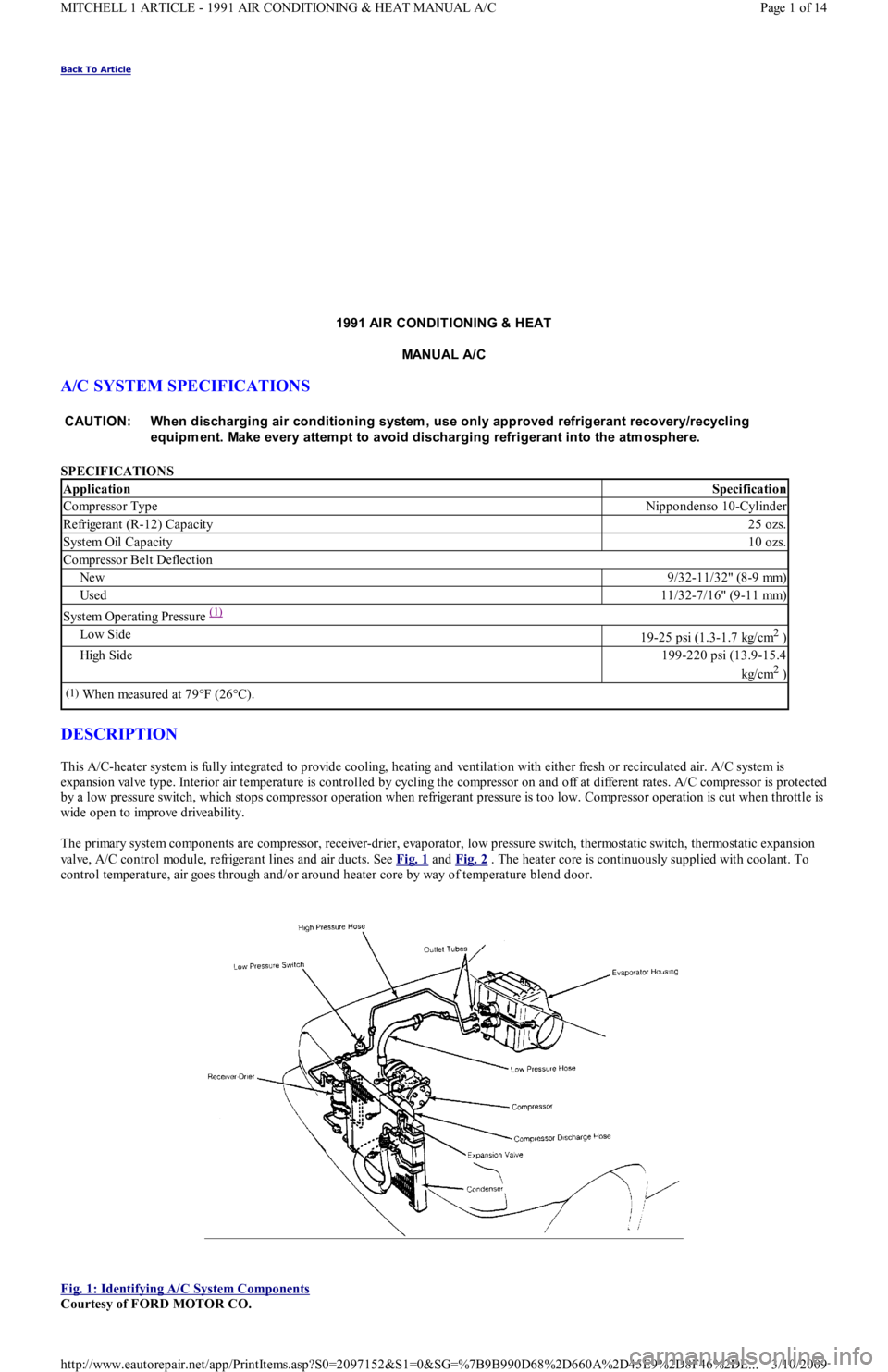
This A/C-heater system is fully integrated to provide cooling, heating and ventilation with either fresh or recirculated air. A/C system is
expansion valve type. Interior air temperature is controlled by cycling the compressor on and off at different rates. A/C compressor is protected
by a low pressure switch, which stops compressor operation when refrigerant pressure is too low. Compressor operation is cut when throttle is
wide open to improve driveability.
The primary system components are compressor, receiver-drier, evaporator, low pressure switch, thermostatic switch, thermostatic expansion
valve, A/C control module, refrigerant lines and air ducts. See Fig. 1
and Fig. 2 . The heater core is continuously supplied with coolant. To
control temperature, air goes through and/or around heater core by way of temperature blend door.
Fig. 1: Identifying A/C System Components
Courtesy of FORD MOTOR CO. CAUT ION: When discharging air conditioning system , use only approved refrigerant recovery/recycling
equipm ent. Make every attem pt to avoid discharging refrigerant into the atm osphere.
ApplicationSpecification
Compressor TypeNippondenso 10-Cylinder
Refrigerant (R-12) Capacity25 ozs.
System Oil Capacity10 ozs.
Compressor Belt Deflection
New9/32-11/32" (8-9 mm)
Used11/32-7/16" (9-11 mm)
System Operating Pressure (1)
Low Side19-25 psi (1.3-1.7 kg/cm2 )
High Side199-220 psi (13.9-15.4
kg/cm
2 )
(1)When measured at 79°F (26°C).
Page 1 of 14 MITCHELL 1 ARTICLE - 1991 AIR CONDITIONING & HEAT MANUAL A/C
3/10/2009 http://www.eautorepair.net/app/PrintItems.asp?S0=2097152&S1=0&SG=%7B9B990D68%2D660A%2D45E9%2D8F46%2DE
...