section 4 FORD FIESTA 2007 Workshop Manual
[x] Cancel search | Manufacturer: FORD, Model Year: 2007, Model line: FIESTA, Model: FORD FIESTA 2007Pages: 1226, PDF Size: 61.26 MB
Page 423 of 1226
303-00-1 Engine System = General Information 303-00-1
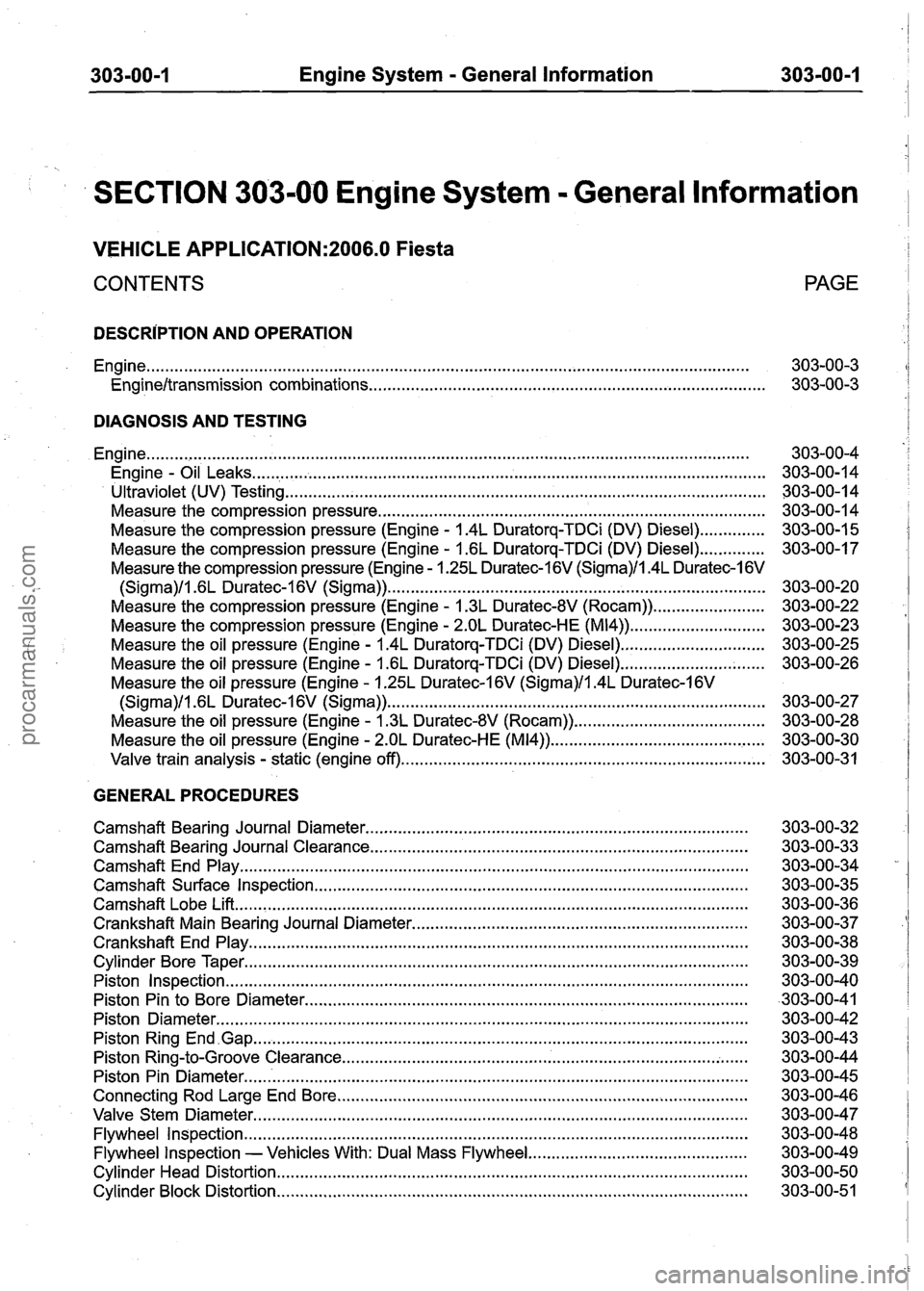
SECTION 303-00 Engine System . General lnformation
VEHICLE APPLICATION:2006.0 Fiesta
CONTENTS PAGE
DESCRIPTION AND
OPERATION
Engine
........................................................................\
......................................................... 303-00-3
Engineltransmission combinations ........................................................................\
........ 303-00-3
DIAGNOSIS AND TESTING
........................................................................\
.......................................................... Engine
. Engine Oil Leaks ........................................................................\
........................................
Ultraviolet (UV) Testing ........................................................................\
...............................
Measure the compression pressure ........................................................................\
...........
.............. Measure the compression pressure (Engine . 1.4L Duratorq-TDCi (DV) Diesel)
Measure the compression pressure (Engine
. 1.6L Duratorq-TDCi (DV) Diesel) ..............
Measure the compression pressure (Engine . 1.25L Duratec-I 6V (Sigma)/l.4L Duratec-I 6V
........................................................................\
......... (Sigma)ll . 6L Duratec-I 6V (Sigma))
Measure the compression pressure (Engine
. 1.3L Duratec-8V (Rocam)) ........................
Measure the compression pressure (Engine . 2.OL Duratec-HE (M14)) .............................
. Measure the oil pressure (Engine 1.4L Duratorq-TDCi (DV) Diesel) ...............................
Measure the oil pressure (Engine . 1.6L Duratorq-TDCi (DV) Diesel) ...............................
Measure the oil pressure (Engine . 1.25L Duratec-1 6V (Sigma)/l.4L Duratec-1 6V
........................................................................\
......... (Sigma)/l . 6L Duratec-1 6V (Sigma))
. Measure the oil pressure (Engine 1.3L Duratec-8V (Rocam)) .........................................
. Measure the oil pressure (Engine 2.OL Duratec-HE (M14)) ...............................................
Valve train analysis . static (engine off) ........................................................................\
......
GENERAL PROCEDURES
Camshaft Bearing Journal Diameter
........................................................................\
..........
Camshaft Bearing Journal Clearance ........................................................................\
.........
Camshaft End Play ........................................................................\
.....................................
Camshaft Surface Inspection ........................................................................\
.....................
........................................................................\
...................................... Camshaft Lobe Lift
Crankshaft Main Bearing Journal Diameter
........................................................................\
Crankshaft End Play ........................................................................\
...................................
Cylinder Bore Taper ........................................................................\
....................................
Piston Inspection ........................................................................\
........................................
Piston Pin to Bore Diameter ........................................................................\
.......................
Piston Diameter ........................................................................\
..........................................
Piston Ring End .Gap ........................................................................\
...................................
............................................ ................................... Piston Ring-to-Groove Clearance ......
Piston Pin Diameter ........................................................................\
.....................................
Connecting Rod Large End Bore ........................................................................\
................
Valve Stem Diameter ........................................................................\
..................................
Flywheel Inspection ........................................................................\
....................................
............................................... Flywheel Inspection - Vehicles With: Dual Mass Flywheel
Cylinder Head Distortion ........................................................................\
.............................
Cylinder Block Distortion ........................................................................\
.............................
procarmanuals.com
Page 455 of 1226
303-00-33 Engine System - General Information 303-00-33
GENERAL PROCEDURES
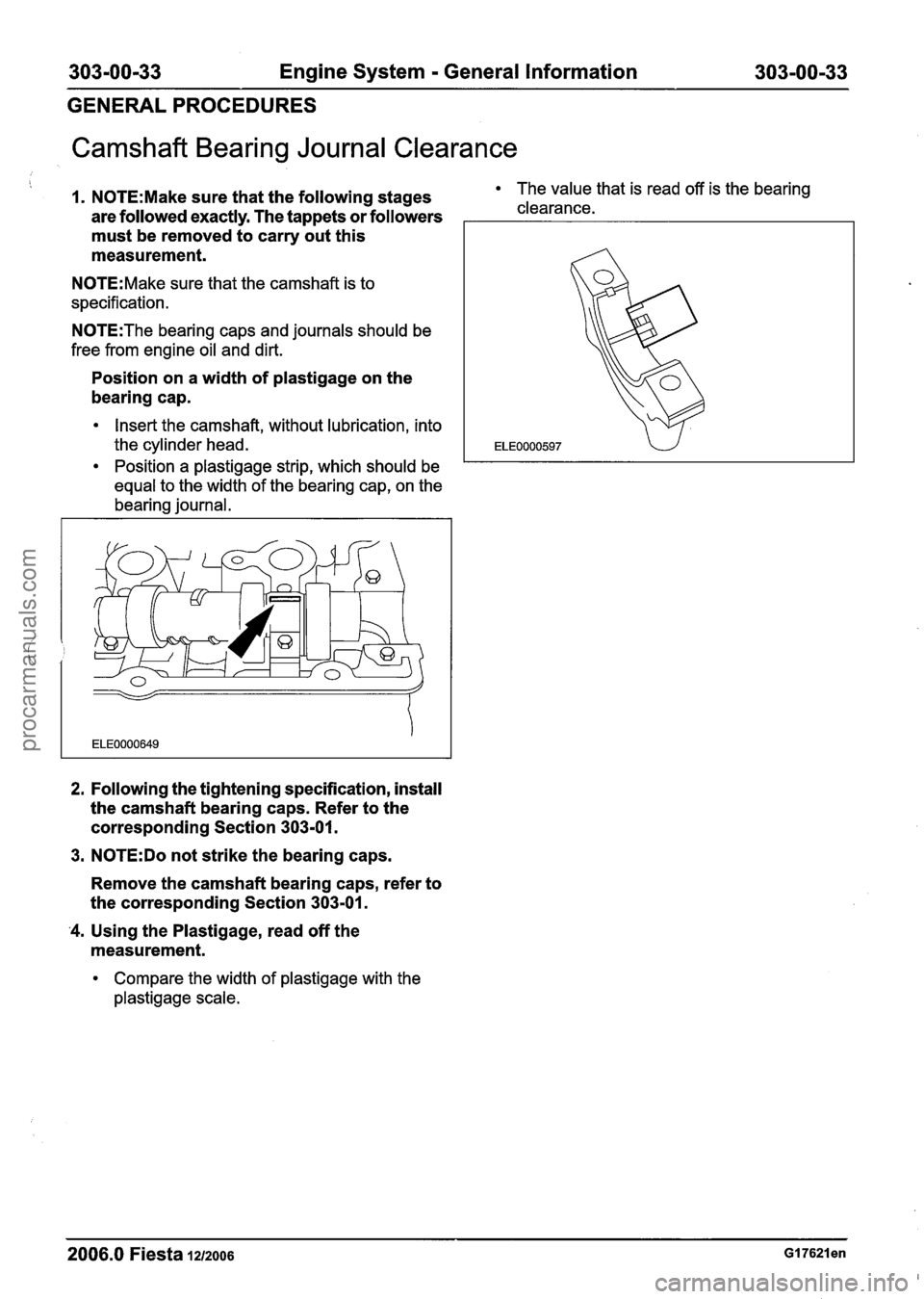
Camshaft Bearing Journal Clearance
1. N0TE:Make sure that the following stages The value that is read off is the bearing
are followed exactly. The tappets or followers clearance.
must be removed to carry out this
measurement.
N0TE:Make sure that the camshaft is to
specification.
N0TE:The bearing caps and journals should be
free from engine oil and dirt.
Position on a width of plastigage on the
bearing cap.
Insert the camshaft, without lubrication, into
the cylinder head.
Position
a plastigage strip, which should be
equal to the width of the bearing cap, on the
bearing journal.
2. Following the tightening specification, install
the camshaft bearing caps. Refer to the
corresponding Section 303-01.
3.
N0TE:Do not strike the bearing caps.
Remove the camshaft bearing caps, refer to
the corresponding Section 303-01.
'4. Using the Plastigage, read off the
measurement.
Compare the width of plastigage with the
plastigage scale.
2006.0 Fiesta 1212006
procarmanuals.com
Page 472 of 1226
303-00-50 Engine System - General Information 303-00-50
GENERAL PROCEDURES
Cylinder Head Distortion
General Equipment
1 Straight edge I
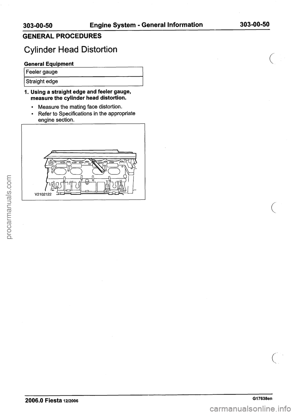
1. Using a straight edge and feeler gauge,
measure the cylinder head distortion.
Measure the mating face distortion.
Refer to Specifications in the appropriate
engine section.
2006.0 Fiesta 1212006 GI 7638en
procarmanuals.com
Page 477 of 1226
303-01 A-I Engine
. 1.25L Duratec-1 6V (Sigma)ll.4L
Duratec-I
6V (Sigma)ll . 6L Duratec-1 6V (Sigma)
303-01 A-I
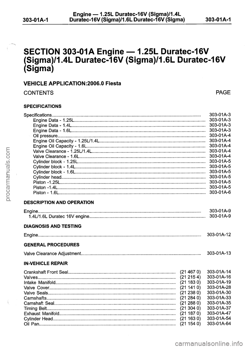
SECTION 303-01A Engine . 1.25L Duratec-1 6V
(Sigma)/l.4L Duratec-I 6V (Sigma)/l . 6L Duratec-1 6V
(Sigma)
VEHICLE APPLICATION:2006.0 Fiesta
CONTENTS
SPECIFICATIONS
........................................................................\
.............................................. Specifications
Engine Data
. 1.25L ........................................................................\
................................
Engine Data . I . 4L ........................................................................\
..................................
Engine Data . 1.6L ........................................................................\
..................................
Oil pressure ........................................................................\
.............................................
Engine Oil Capacity . - 1.25Ll1.4L ........................................................................\
............
Engine Oil Capacity - 1.6L ........................................................................\
......................
Valve Clearance - 1.25LlI . 4L ........................................................................\
..................
Valve Clearance - 1.6L ........................................................................\
............................
Cylinder block - 1.25L ........................................................................\
.............................
Cylinder block - 1.4L ........................................................................\
...............................
........................................................................\
............................... Cylinder block - 1.6L
........................................................................\
.......................................... Cylinder head
Piston
-1.25L ........................................................................\
...........................................
Piston -1.4L ........................................................................\
.............................................
Piston - l.6L ........................................................................\
............................................
PAGE
DESCRIPTION AND OPERATION
........................................................................\
......................................................... Engine 303-01A-9
........................................................................\
.................... 1.4Ll1.6L Duratec 16V engine 303-01A-9
DIAGNOSIS AND TESTING
........................................................................\
......................................................... Engine 303-01A-12
GENERAL PROCEDURES
........................................................................\
....................... Valve Clearance Adjustment 303-01 A-I 3
IN-VEHICLE REPAIR
Crankshaft Front Seal ........................................................................\
......... (21 467 0)
Valves ........................................................................\
..................................... (21 21 5 4)
Intake Manifold ........................................................................\
....................... (21 183 0)
Valve Cover ........................................................................\
............................ (21 141 0)
Valve Seals ........................................................................\
............................. (21 238 0)
Camshafts ........................................................................\
........................ (21 284 0)
Camshaft Seal ........................................................................\
................... (21 288 0)
Timing Belt ........................................................................\
.......................... (21 304 0)
Exhaust Manifold ........................................................................\
.................... (21 187 0)
Cylinder Head ........................................................................\
...................... (21 163 0)
Oil Pan ........................................................................\
............................. (21 154 0)
procarmanuals.com
Page 484 of 1226
Engine - I .25L Duratec-1 6V (Sigma)llI4L
Duratec-1 6V (Sigma)ll .6L Duratec-I 6V (Sigma)
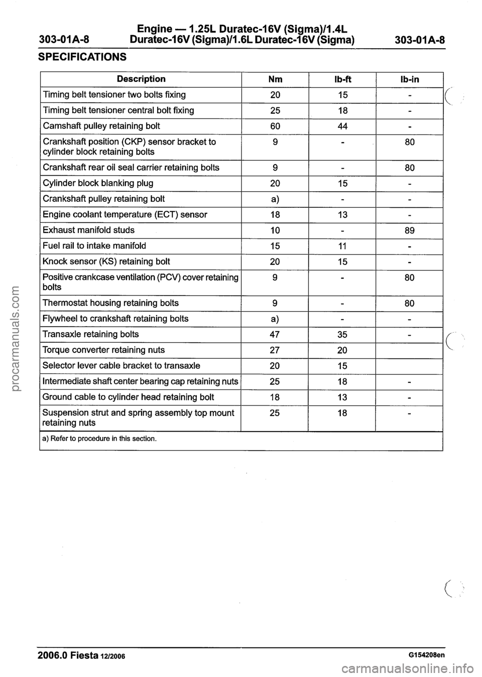
SPECIFICATIONS
1 Description I Nm I Ib-ft I Ib-in I
I Camshaft pulley retaining bolt I 60 I 44 I - I
Timing belt tensioner two bolts fixing
Timing belt tensioner central bolt fixing
Crankshaft position (CKP) sensor bracket to
cylinder block retaining bolts
I Crankshaft rear oil seal carrier retaining bolts I 9 1 - I 80 I
20
25
I Cylinder block blanking plug I 20 I 15 1 - I
I Crankshaft pulley retaining bolt I a) I - I - I
15
18
I Engine coolant temperature (ECT) sensor I 18 I 13 I - I
-
-
I Exhaust manifold studs I 10 I - I 89 I
Positive crankcase ventilation (PCV) cover retaining
1 bolts Fuel
rail to intake manifold
Knock sensor (KS) retaining bolt
I Thermostat housing retaining bolts I 9 I - 1 80 I
I Flywheel to crankshaft retaining bolts I a) I - I - I
15
20
I Selector lever cable bracket to transaxle I 20 I 15 I I
11
15
Transaxle retaining bolts
Torque converter retaining nuts
I Intermediate shaft center bearing cap retaining nuts 1 25 I 18 I - I
-
-
I Ground cable to cylinder head retaining bolt I 18 I 13 I - I
47
27
Suspension strut and spring assembly top mount
retaining nuts
I a) Refer to procedure in this section.
35
20
2006.0 Fiesta 1212006 GI 54208en
-
procarmanuals.com
Page 488 of 1226
Engine - 1.25L Duratec-1 6V (Sigma)ll.4L
303-01 A-I 2 Duratec-1 6V (Sigma)ll .6L Duratec-1 6V (Sigma) 303-01A-I 2
DIAGNOSIS AND TESTING
Enaine
REFER to Section 303-00 [Engine System -
General Information].
2006.0 Fiesta 1212006 GI 7645en
procarmanuals.com
Page 489 of 1226
Engine - 1.25L Duratec-1 6V (Sigma)ll.4L
303-01 A-I 3 Duratec-1 6V (Sigma)ll.GL Duratec-1 6V (Sigma) 303-01 A-I
3
GENERAL PROCEDURES
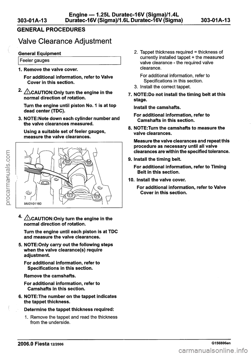
Valve Clearance Adjustment
1. Remove the valve cover. clearance.
I
General Equipment 2. Tappet thickness required = thickness of
currently installed tappet
+ the measured
For additional information, refer to Valve For additional information, refer to
Cover in this section. Specifications in this section.
3. Install the correct tappet.
*' ~AUTION:O~~Y turn the engine in the 7. NOTE:Do not install the timing belt at this normal direction of rotation.
stage.
Feeler gauges
Turn the engine until piston No. 1 is at top
Install the camshafts.
dead center (TDC).
For additional information, refer to
3. N0TE:Note down each cylinder number and
Camshafts in this section.
the valve clearances measured.
8. N0TE:Turn the camshafts to measure the
Using a suitable set of feeler gauges,
valve clearances.
measure the valve clearances.
Measure the valve clearances and repeat this
valve clearance - the required valve
procedure as necessary until all valve
clearances are within the specified tolerance.
9. Install the timing belt.
For additional information, refer to Timing
Belt in this section.
10, Install the valve cover.
For additional information, refer to Valve
Cover in this section.
4m ~CAUTION:O~I~ turn the engine in the
normal direction of rotation.
Turn the engine until each piston is at TDC
and measure the valve clearances.
5. N0TE:Only carry out the following steps
when the valve
clearance(s) require
adjustment.
For additional information, refer to
Specifications in this section.
Remove the camshafts.
For additional information, refer to
Camshafts in this section.
6. N0TE:The number on the tappet indicates
the tappet thickness.
Determine the tappet thickness required:
1. Remove the tappet and read the thickness
from the underside.
2006.0 Fiesta 1212006 GI 56806en
procarmanuals.com
Page 492 of 1226
Engine - 1.25L Duratec-1 6V (Sigma)ll.4L
303-OIA-I 6 Duratec-1 6V (Sigma)ll .6L Duratec-1 6V (Sigma) 303-OIA-I 6
IN-VEHICLE REPAIR
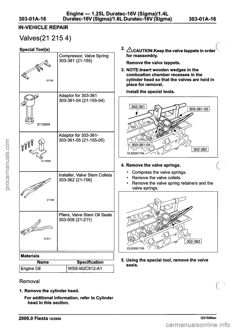
Special Tool(s1
Compressor, Valve Spring
303-36 1 (2 1
-1 55)
Adaptor for 303-361
303-36 1 -04 (2 1 -1 55-04)
I I Adaptor for 303-361 - I
4. Remove the valve springs.
Materials Name Specification
I Engine Oil I WSS-M2C912A1 I
*' ~CAUTION:K~~~ the valve tappets in order\-
for reassembly.
Remove the valve tappets.
3. N0TE:lnset-t wooden wedges in the
combustion chamber recesses in the
cylinder head so that the valves are held in
place for removal.
Install the special tools.
I I Installer, Valve Stem Collets I
I I Pliers, Valve Stem Oil Seals I
Removal
1. Remove the cylinder head.
For additional information, refer to Cylinder
head in this section.
Compress the valve springs.
Remove the valve collets.
Remove the valve spring retainers and the
valve springs.
5. Using the special tool, remove the valve
seals.
2006.0 Fiesta 1212006 G21048en
procarmanuals.com
Page 494 of 1226
Engine - 1.25L Duratec-1 6V (Sigma)ll.4L
303-01 A-I 8 Duratec-16V (Sigma)ll .6L Duratec-1 6V (Sigma) 303-01 A-I 8 - - -
IN-VEHICLE REPAIR
8. Install the cylinder head.
For additional information, refer to Cylinder
head in this section.
2006.0 Fiesta 1212006 G21048en
procarmanuals.com
Page 495 of 1226
Engine - 1.25L Duratec-I 6V (Sigma)ll.4L
303-01A-I 9 Duratec-1 6V (Sigma)/l .6L Duratec-1 6V (Sigma) 303-OIA-I 9
IN-VEHICLE REPAIR
Intake Manifold(21 183 0)
Removal 6. Remove the intake manifold lower retaining
bolt.
A WARNING:Do not smoke or carry lighted
tobacco or open flame of any type when
working on or near any fuel related
components. Highly flammable mixtures
are always present and may ignite. Failure
to follow these instructions may result in
personal injury.
1. Release the fuel system pressure. For
additional information, refer to
Section
31 0-00 [Fuel System - General
Information].
2. Disconnect the battery ground cable. For
additional information, refer to
Section
414-01 [Battery, Mounting and 7. Disconnect the engine wiring harness
Cables]. electrical connector.
3. Remove the air cleaner. For additional
information, refer to Section
303-1 2 [Intake
Air Distribution and Filtering].
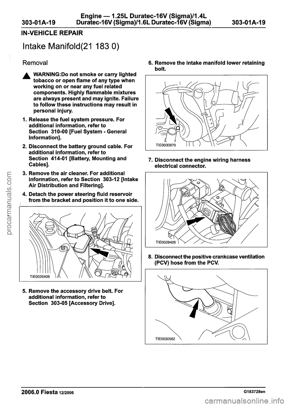
4. Detach the power steering fluid reservoir
from the bracket and position
it to one side.
5. Remove the accessory drive belt. For
additional information, refer to
Section
303-05 [Accessory Drive].
8. Disconnect the positive crankcase ventilation
(PCV) hose from the PCV.
2006.0 Fiesta 1212006 GI 83728en
procarmanuals.com