FORD FIESTA 2007 Workshop Manual
Manufacturer: FORD, Model Year: 2007, Model line: FIESTA, Model: FORD FIESTA 2007Pages: 1226, PDF Size: 61.26 MB
Page 151 of 1226
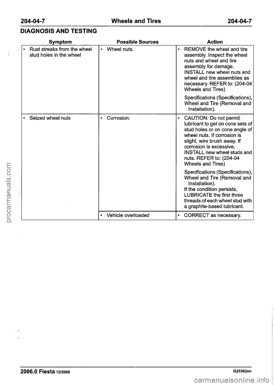
204-04-7 Wheels and Tires 204-04-7
DIAGNOSIS AND TESTING
Symptom
Rust streaks from the wheel
stud holes in the wheel
Seized wheel nuts
Possible Sources
Wheel nuts.
Corrosion.
Vehicle overloaded
Action
REMOVE the wheel and tire
assembly. Inspect the wheel
nuts and wheel and tire
assembly for damage.
INSTALL new wheel nuts and
wheel and tire assemblies as
necessary. REFER to: (204-04
Wheels and Tires)
Specifications (Specifications),
Wheel and Tire (Removal and
Installation).
CAUTION: Do not permit
lubricant to get on cone sets of
stud holes or on cone angle of
wheel nuts. If corrosion is
slight, wire brush away. If
corrosion is excessive,
INSTALL new wheel studs and
nuts. REFER to: (204-04
Wheels and Tires)
Specifications (Specifications),
Wheel and Tire (Removal and
Installation).
If the condition persists,
LUBRICATE the first three
threads of each wheel stud with
a graphite-based lubricant.
CORRECT as necessary.
2006.0 Fiesta 1212006 G25362en
procarmanuals.com
Page 152 of 1226
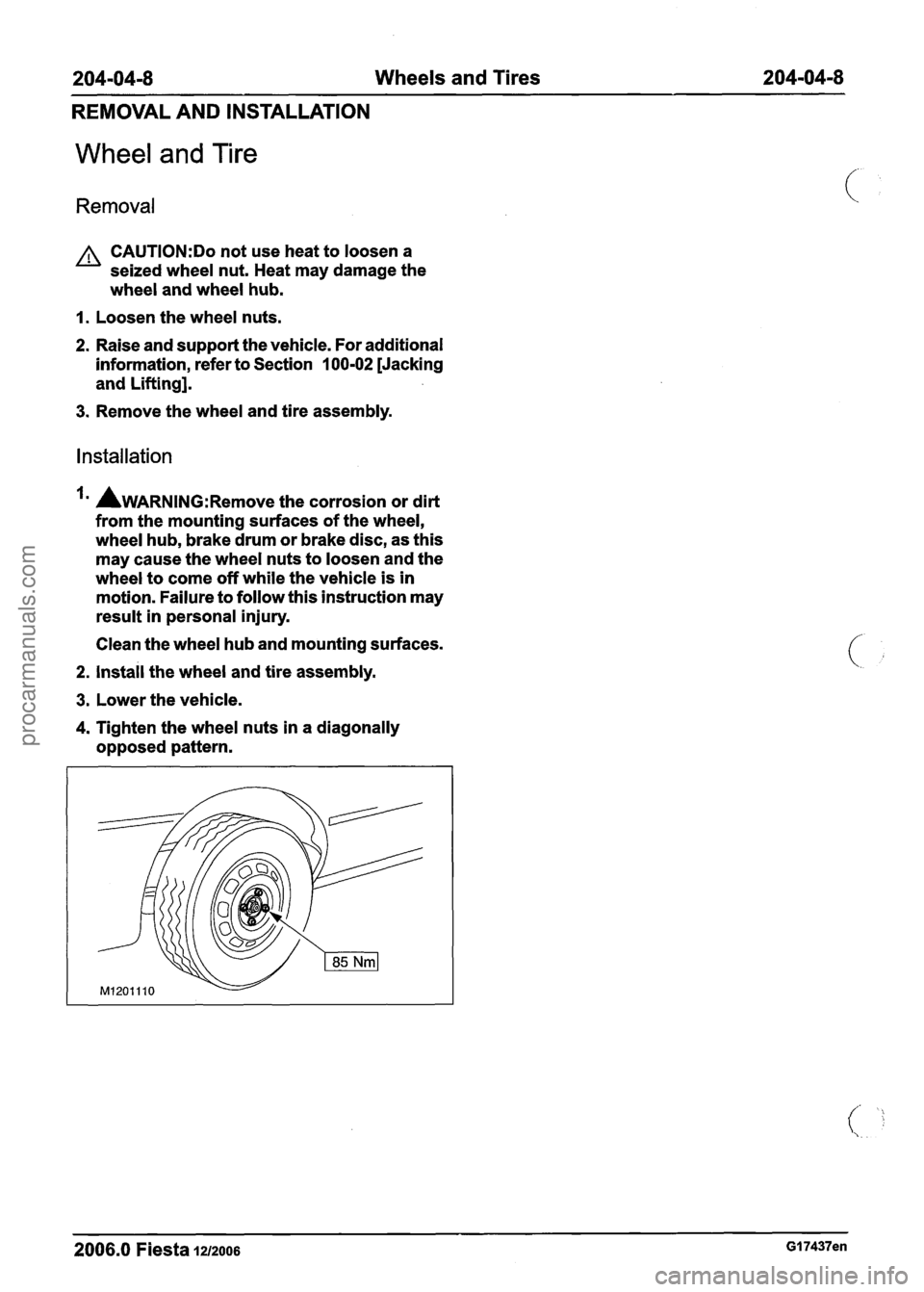
204-04-8 Wheels and Tires 204-04-8
REMOVAL AND INSTALLATION
Wheel and Tire
Removal
A CAUTI0N:Do not use heat to loosen a
seized wheel nut. Heat may damage the
wheel and wheel hub.
I. Loosen the wheel nuts.
2. Raise and support the vehicle. For additional
information, refer to Section
100-02 [Jacking
and Lifting].
3. Remove the wheel and tire assembly.
Installation
AWARNING:R~~~~~ the corrosion or dirt
from the mounting surfaces of the wheel,
wheel hub, brake drum or brake disc, as this
may cause the wheel nuts to loosen and the
wheel to come off while the vehicle is in
motion. Failure to follow this instruction may
result in personal injury.
Clean the wheel hub and mounting surfaces.
2. install the wheel and tire assembly.
3. Lower the vehicle.
4. Tighten the wheel nuts in a diagonally
opposed pattern.
2006.0 Fiesta 1212006 GI 7437en
procarmanuals.com
Page 153 of 1226
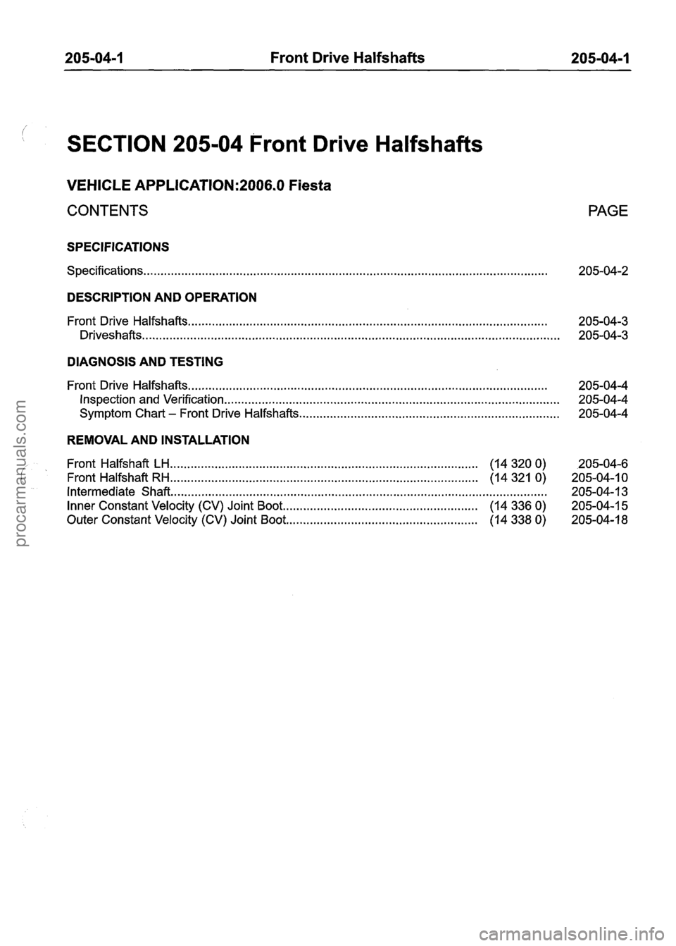
205-04-1 Front Drive Halfshafts 205-04-1
SECTION 205-04 Front Drive Halfshafts
VEHICLE APPLICATION:2006.0 Fiesta
CONTENTS
SPECIFICATIONS
Specifications ........................................................................\
..............................................
PAGE
DESCRIPTION AND OPERATION
........................................................................\
................................. Front Drive Halfshafts 205-04-3
........................................................................\
.................................................. Driveshafts 205-04-3
DIAGNOSIS AND TESTING
........................................................................\
................................. Front Drive Halfshafts 205-04-4
Inspection and Verification ........................................................................\
.......................... 205-04-4
........................................................................\
.... Symptom Chart - Front Drive Halfshafts 205-04-4
REMOVAL AND INSTALLATION
........................................................................\
.................. Front Halfshaft LH (14 320 0) 205-04-6
........................................................................\
.................. Front Halfshaft RH (14 321 0) 205-04-1 0
Intermediate Shaft ........................................................................\
...................................... 205-04-1 3
......................................................... Inner Constant Velocity (CV) Joint Boot (14 336 0) 205-04-1 5
........................................................ Outer Constant Velocity (CV) Joint Boot (14 338 0) 205-04-18
procarmanuals.com
Page 154 of 1226
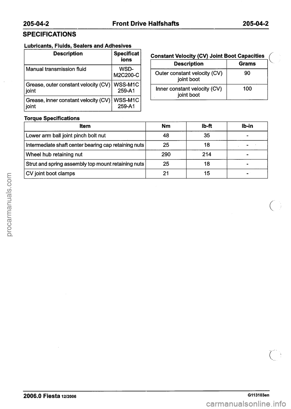
205-04-2 Front Drive Halfshafts 205-04-2
SPECIFICATIONS
Lubricants, Fluids, Sealers and Adhesives
Description
/ Specificat 1
ions
Manual transmission fluid
Grease, outer constant velocity (CV) WSS-MI C
joint
1 259-A1 1
Grease, inner constant velocity (CV) WSS-MI C
joint
1 259-A1 1
Toraue S~ecifications
Outer constant velocity (CV) joint boot
Constant Velocity (CV) Joint Boot Capacities
Inner constant velocity (CV)
joint boot
Description
I Lower arm ball joint pinch bolt nut I 48 I 35 I - I
Grams
I Intermediate shaft center bearing cap retaining nuts I 25 I 18 I - I
I Wheel hub retaining nut 1 290 1214 1 - I
I Strut and spring assembly top mount retaining nuts I 25 I 18 I - I
I CV joint boot clamps I 21 I 15 I - I
2006.0 Fiesta iu200s GII 3103en
procarmanuals.com
Page 155 of 1226
205-04-3 Front Drive Halfshafts 205-04-3
DESCRIPTION AND OPERATION
Front Drive Halfshafts
Drives hafts
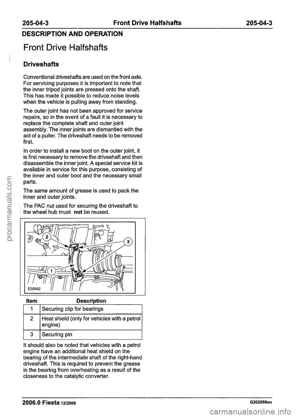
Conventional driveshafts are used on the front axle.
For servicing purposes it is important to note that
the inner tripod joints are pressed onto the shaft.
This has made it possible to reduce noise levels
when the vehicle is pulling away from standing.
The outer joint has not been approved for service
repairs, so in the event of a fault it is necessary to
replace the complete shaft and outer joint
assembly. The inner joints are dismantled with the
aid of a puller. The driveshaft needs to be removed
first.
In order to install a new boot on the outer joint, it
is first necessary to remove the driveshaft and then
disassemble the inner joint. A special service kit is
available in service for this purpose, consisting of
the inner and outer boot and the necessary small
parts.
The same amount of grease is used to pack the
inner and outer joints.
- The PAC nut used for securing the driveshaft to ' the wheel hub must not be reused.
Item Description
I 1 I Securing clip for bearings I
Heat shield (only for vehicles with a petrol
1 * 1 engine)
It should also be noted that vehicles with a petrol
engine have an additional heat shield on the bearing of the intermediate shaft of the right-hand
driveshaft. This is required to prevent the grease
in the bearing from overheating as a result of the
closeness to the catalytic converter.
2006.0 Fiesta 1212006 G202088en
procarmanuals.com
Page 156 of 1226
205-0414 Front Drive Halfshafts 205-04-4
DIAGNOSIS AND TESTING
Front Drive Halfshafts
Inspection and Verification 3. If an obvious cause for an observed or reported
concern is found, correct the cause (if possible) c.# '
1. Verify the customer concern. before proceeding
to the next step.
2. Visually inspect for obvious signs of mechanical
or electrical damage.
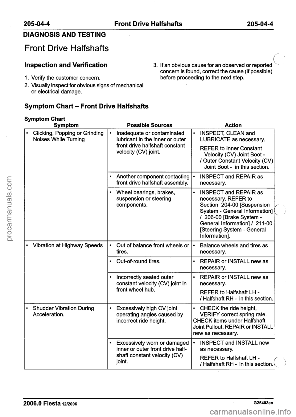
Symptom Chart - Front Drive Halfshafts
Symptom Chart
Symptom
Possible Sources Action
Clicking, Popping or Grinding
Noises While Turning Inadequate or contaminated INSPECT, CLEAN and
I lubricant in the inner or outer I LUBRICATE as necessary.
I Outer Constant Velocity (CV)
I Joint Boot - in this section.
front drive halfshaft constant
velocity (CV) joint.
REFER to Constant
Velocity (CV) Joint Boot -
Wheel bearings, brakes,
suspension or steering
components.
Another component contacting
front drive halfshaft assembly.
--
INSPECT and REPAIR as
necessary. REFER to
Section 204-00 [Suspension
System
- General Information]
1 206-00 [Brake System -
General Information] I 21 1-00
[Steering System
- General
Information].
INSPECT and REPAIR as
necessary.
- --
Vibration at Highway Speeds
Shudder Vibration During
Acceleration. Out of balance front wheels or
tires. Balance wheels and tires as
necessary.
I Incorrectly seated outer I REPAIR or INSTALL new as I
Out-of-round tires.
constant velocity (CV) joint in necessary.
front wheel hub.
I REFER to Halfshaft LH -
REPAIR or INSTALL new as
necessary.
I I I Halfshaft RH - in this section. I
Excessively high CV joint
operating angles caused by
incorrect ride height. CHECK the ride height,
VERIFY correct spring rate.
CHECK items under Halfshaft
Joint Pullout. REPAIR or INSTALL
new as necessary.
Excessively worn or damaged
I inner or outer front drive half-
- - - - --
2006.0 Fiesta 1212006 G25403en
INSPECT and INSTALL new
as necessary.
shaft constant velocity (CV)
joint. REFER
to Halfshaft LH
-
I Halfshaft RH - in this sectionk 1;
procarmanuals.com
Page 157 of 1226
205-04-5 Front Drive Halfshafts 205-04-5
DIAGNOSIS AND TESTING
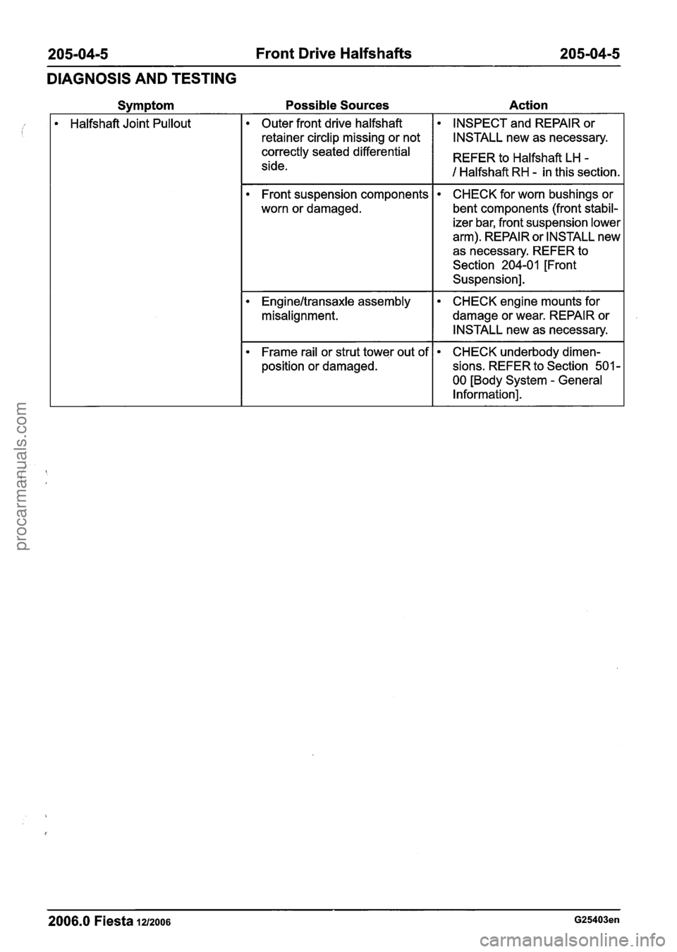
Possible Sources Action
Halfshaft Joint Pullout Outer front drive halfshaft INSPECT
and REPAIR or
retainer circlip missing or not
I I INSTALL new as necessary.
Front suspension components
worn or damaged.
correctly seated differential
side. CHECK
for worn bushings or
bent components (front stabil-
izer bar, front suspension lower
arm). REPAIR or INSTALL new
as necessary. REFER to
Section
204-01 [Front
Suspension]. REFER to Halfshaft
LH
-
1 Halfshaft RH - in this section.
Engineltransaxle assembly
misalignment. CHECK engine mounts for
damage or wear. REPAIR or
INSTALL new as necessary.
Frame rail or strut tower out of
position or damaged. CHECK underbody dimen-
sions. REFER to Section
501 -
00 [Body System - General
Information].
-- - --
2006.0 Fiesta 1212006 G25403en
procarmanuals.com
Page 158 of 1226
205-04-6 Front Drive Halfshafts 205-04-6
REMOVAL AND INSTALLATION
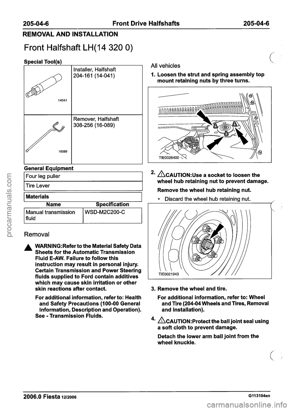
Front Halfshaft LH(14 320 0)
I I Installer, Halfshaft
(%. .
1 All vehicles
1. Loosen the strut and spring assembly top
mount retaining nuts by three turns.
General
Eaui~ment
I Four leg puller I
Tire Lever
Materials
Name Specification
Removal
Manual transmission
1 fluid
A WARNING:Refer to the Material Safety Data
Sheets for the Automatic Transmission
Fluid
E-AW. Failure to follow this
instruction may result in personal injury.
Certain Transmission and Power Steering
fluids supplied to Ford contain additives
which may cause skin irritation or other
skin reactions after contact.
WSD-M2C200-C
2' ACAUTION:~~~ a socket to loosen the
wheel hub retaining nut to prevent damage.
Remove the wheel hub retaining nut.
Discard the wheel hub retaining nut. ,'
3. Remove the wheel and tire.
For additional information, refer to: Health For
additional information, refer to: Wheel
and Safety Precautions
(1 00-00 General and
Tire (204-04 Wheels and Tires, Removal
Information, Description and Operation). and
Installation).
See
- Transmission Fluids.
4m Ac~u~10~:~rotect the ball joint seal using
a soft cloth to prevent damage.
Detach the lower arm ball joint from the
wheel knuckle.
2006.0 Fiesta IZIZOO~ G113104en
procarmanuals.com
Page 159 of 1226
205-04-7 Front Drive Halfshafts 205-04-7
REMOVAL AND INSTALLATION
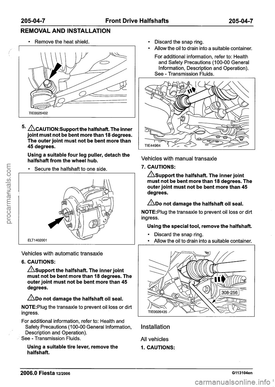
Remove the heat shield.
5m ~~~~~~~~~~~~~~~t the halfshaft. The inner
joint must not be bent more than
18 degrees.
The outer joint must not be bent more than
45 degrees.
Using a suitable four leg puller, detach the
halfshaft from the wheel hub.
Secure the halfshaft to one side.
Vehicles with automatic transaxle
6. CAUTIONS:
A~upport the halfshaft. The inner joint
must not be bent more than
18 degrees. The
outer joint must not be bent more than
45
degrees.
ADO not damage the halfshaft oil seal.
N0TE:Plug the transaxle to prevent oil loss or dirt
ingress.
For additional information, refer to: Health and
Safety Precautions (1 00-00 General Information,
Description and Operation).
See
- Transmission Fluids.
Using a suitable tire lever, remove the
halfs haft.
Discard the snap ring.
Allow the oil to drain into a suitable container.
For additional information, refer to: Health
and Safety Precautions (1 00-00 General
Information, Description and Operation).
See
- Transmission Fluids.
Vehicles with manual transaxle
7. CAUTIONS:
Asupport the halfshaft. The inner joint
must not be bent more than
I8 degrees. The
outer joint must not be bent more than
45
degrees.
ADO not damage the halfshaft oil seal.
N0TE:Plug the transaxle to prevent oil loss or dirt
ingress.
Using the special tool, remove the halfshaft.
Discard the snap ring.
Allow the oil to drain into a suitable container.
Installation
All vehicles
I. CAUTIONS:
2006.0 Fiesta 1212006 GI 131 04en
procarmanuals.com
Page 160 of 1226
205-0418 Front Drive Halfshafts 205-0418
REMOVAL AND INSTALLATION
Asupport the halfshaft. The inner joint
must not be bent more than 18 degrees. The
outer joint must not be bent more than
45
degrees.
ADO not damage the halfshaft oil seal.
AMake sure the snap ring is correctly
seated.
N0TE:lnstall a new snap ring.
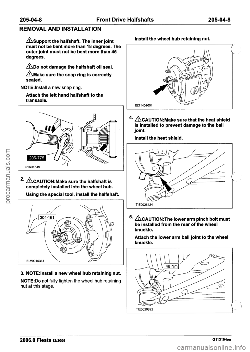
Attach the left hand halfshaft to the
transaxle.
*' ACAUTION:M~~~ sure the halfshaft is
completely installed into the wheel hub.
Using the special tool, install the halfshaft.
3. N0TE:lnstall a new wheel hub retaining nut.
N0TE:Do not fully tighten the wheel hub retaining
nut at this stage. Install
the wheel hub retaining nut.
4m ACAUTION:M~~~ sure that the heat shield
is installed to prevent damage to the ball
joint.
Install the heat shield.
~CAUTION:T~~ lower arm pinch bolt must
be installed from the rear of the wheel
knuckle.
Attach the lower arm ball joint to the wheel
knuckle.
2006.0 Fiesta 1212006 G113104en
procarmanuals.com