FORD FIESTA 2007 Workshop Manual
Manufacturer: FORD, Model Year: 2007, Model line: FIESTA, Model: FORD FIESTA 2007Pages: 1226, PDF Size: 61.26 MB
Page 111 of 1226

204-01 =I 3 Front Suspension 204-01 -1 3
REMOVAL AND INSTALLATION
Wheel Knuckle(l4 343 0)
I Special Tool(s)
I Lever, Wheel Knuckle
I I Installer, Halfshaft I
I I Separator, Ball Joint I
2. Loosen the strut and spring assembly top
mount retaining nuts by five turns.
3. Remove the wheel and tire.
For additional information, refer to: Wheel
and Tire
(204-04 Wheels and Tires, Removal
and Installation).
4. N0TE:Make a note of the position of the
brake hose, to aid installation.
Detach the brake hose from the brake hose
support bracket.
--
General Equipment Remove the retaining clip.
Three leg puller
Removal
All vehicles
1. Loosen the wheel hub retaining nut.
'' &AUTION:S~~~~~~ the brake caliper and
anchor plate to prevent load being placed
on the brake hose.
2006.0 Fiesta 1212006 GI 83759en
procarmanuals.com
Page 112 of 1226
204-01 -1 4 Front Suspension 204-01 -1 4
REMOVAL AND INSTALLATION
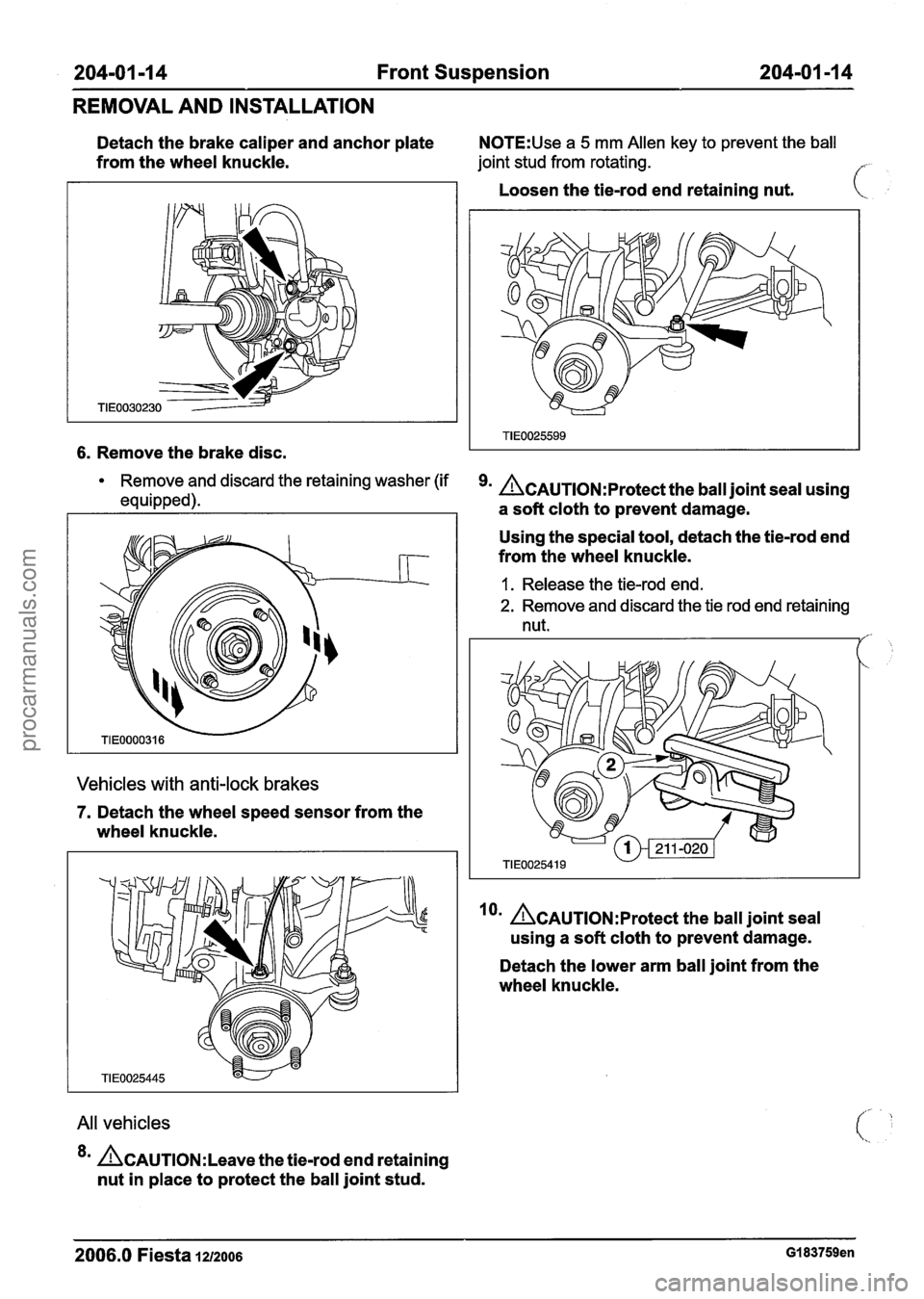
Detach the brake caliper and anchor plate N0TE:Use a 5 mm Allen key to prevent the ball
from the wheel knuckle. joint stud from rotating. f
6. Remove the brake disc.
Remove and discard the retaining washer (if
equipped).
Vehicles with anti-lock brakes
7. Detach the wheel speed sensor from the
wheel knuckle.
All vehicles
*= &AUTION:L~~~~ the tie-rod end retaining
nut in place to protect the ball joint stud. Loosen
the tie-rod end retaining nut.
k
&AuTl~N:~rotect the ball joint seal using
a soft cloth to prevent damage.
Using the special tool, detach the tie-rod end
from the wheel knuckle.
1. Release the tie-rod end.
2. Remove and discard the tie rod end retaining
nut.
/'-
lorn A~AuT10N:~rotect the ball joint seal
using a soft cloth to prevent damage.
Detach the lower arm ball joint from the
wheel knuckle.
2006.0 Fiesta 1212006 GI 83759en
procarmanuals.com
Page 113 of 1226

204-01 -1 5 Front Suspension 204-01 -1 5
REMOVAL AND INSTALLATION
Remove the heat shield. Using a suitable three leg puller, detach the
wheel hub from the halfshaft.
11. Remove and discard the wheel hub
retaining nut.
14. Using the special tool, remove the wheel
knuckle.
12. Remove the wheel knuckle to suspension
strut pinch bolt.
Installation
13. N0TE:Support the halfshaft. The inner joint
must not be bent more than
18 degrees.
The outer joint must not be bent more than
45 degrees.
All vehicles
I. Install the wheel knuckle.
2m ~CAUTION:M~~~ sure the halfshaft is
completely installed into the wheel hub.
2006.0 Fiesta 1212006 GI 83759en
procarmanuals.com
Page 114 of 1226
204-01 -1 6 Front Suspension 204-01 -1 6
REMOVAL AND INSTALLATION
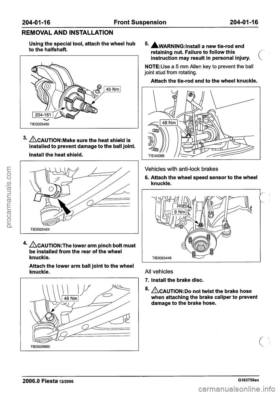
Using the special tool, attach the wheel hub 5. AWARNING:lnstall a new tie-rod end to the halfshaft.
retaining nut. Failure to follow this f
3m ACAUTION:M~~~ sure the heat shield is
installed to prevent damage to the ball joint.
Install the heat shield.
4m &AUTION:T~~ lower arm pinch bolt must
be installed from the rear of the wheel
knuckle. instruction
may result in personal injury.
N0TE:Use a 5 mm Allen key to prevent the ball
joint stud from rotating.
Attach the tie-rod end to the wheel knuckle.
Vehicles with anti-lock brakes
6. Attach the wheel speed sensor to the wheel
knuckle.
Attach the lower arm ball joint to the wheel
knuckle.
All vehicles
7. Install the brake disc.
8m &AUTION:DO not twist the brake hose
when attaching the brake caliper to prevent
damage to the brake hose.
2006.0 Fiesta 1212006 GI 83759en
procarmanuals.com
Page 115 of 1226
204-01 -1 7 Front Suspension 204-01 -1 7
REMOVAL AND INSTALLATION
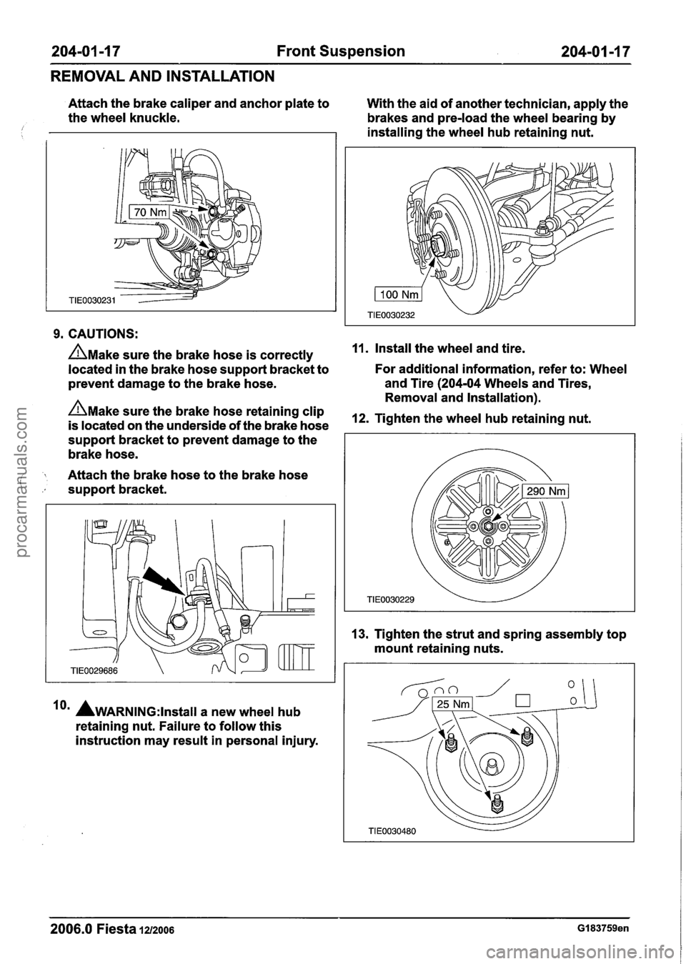
Attach the brake caliper and anchor plate to
With the aid of another technician, apply the
the wheel knuckle.
brakes and pre-load the wheel bearing by
/ 1 I installing the wheel hub retaining nut.
9. CAUTIONS:
AMake sure the brake hose is correctly 11. Install the wheel and tire.
located in the brake hose support bracket to For additional
information, refer to: Wheel
prevent damage to the brake hose.
A
and Tire (204-04 Wheels and Tires,
Removal and Installation).
AMake sure the brake hose retaining clip 12m Tighten the wheel hub retaining nut. is located on the underside of the brake hose
support bracket to prevent damage to the
brake hose.
j Attach the brake hose to the brake hose
support bracket.
lo' AwARNING:~~~~~~~ a new wheel hub
retaining nut. Failure to follow this
instruction may result in personal injury. 13.
Tighten the strut and spring assembly top
mount retaining nuts.
--
2006.0 Fiesta 1212006 GI 83759en
procarmanuals.com
Page 116 of 1226
204-01 -1 8 Front Suspension 204-01-1 8
REMOVAL AND INSTALLATION
14. Check the toe setting and adjust as
necessary.
For additional information, refer to:
Specifications (204-00 Suspension
System
- General Information,
Specifications).
2006.0 Fiesta 1212006 GI 83759en
procarmanuals.com
Page 117 of 1226
204-01 -1 9 Front Suspension 204-01 -1 9
REMOVAL AND INSTALLATION
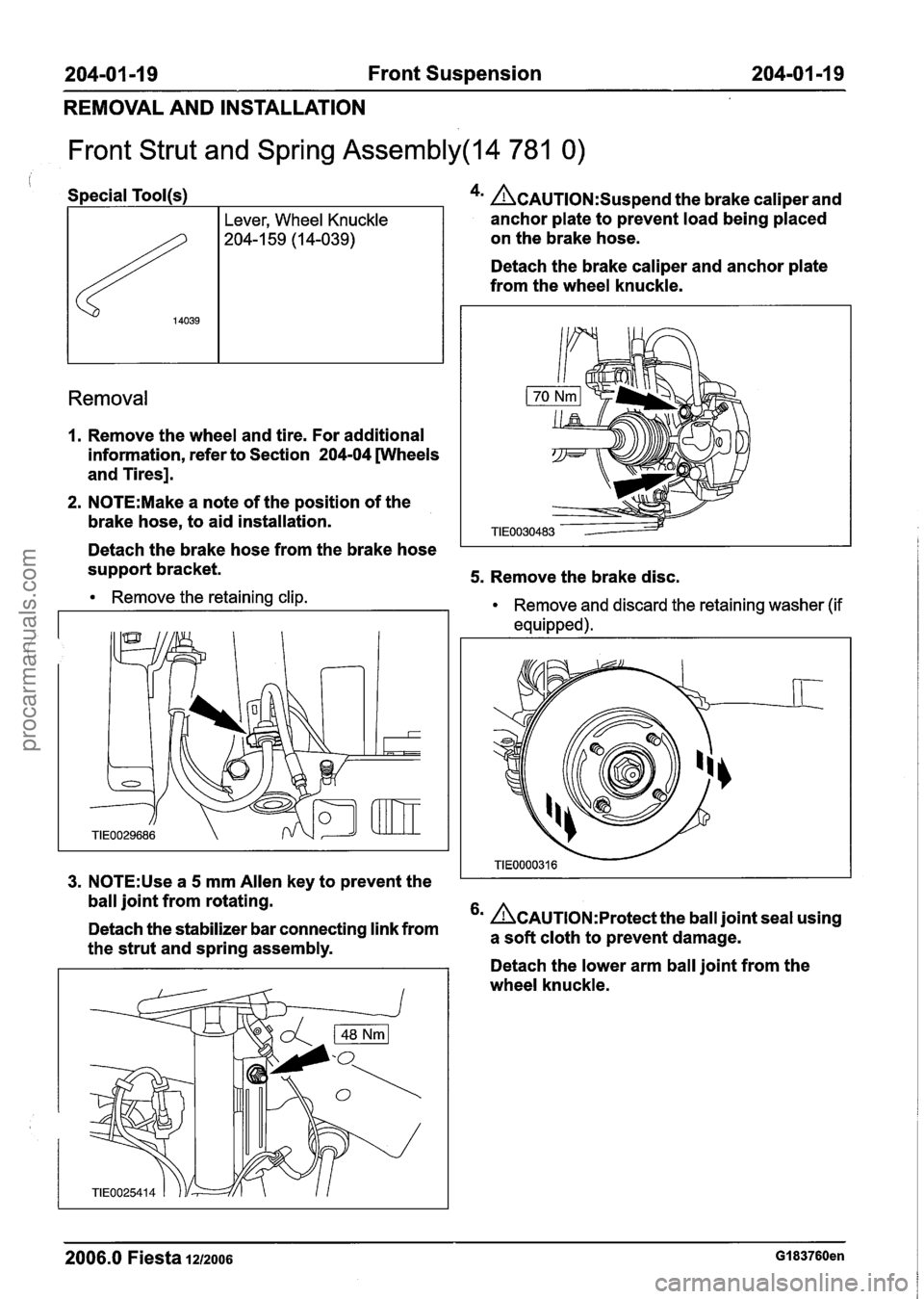
Front Strut and Spring Assembly(l4 781 0)
, Special Tool(s)
I Lever, Wheel Knuckle
- 4m &AUTION:S~~~~~~ the brake caliper and
anchor plate to prevent load being placed
on the brake hose.
Detach the brake caliper and anchor plate
from the wheel knuckle.
Removal
1. Remove the wheel and tire. For additional
information, refer to Section
204-04 wheels
and Tires].
2. N0TE:Make a note of the position of the
brake hose, to aid installation.
Detach the brake hose from the brake hose
support bracket.
5. Remove the brake disc.
Remove the retaining clip.
Remove and discard the retaining washer (if
equipped).
I
3. N0TE:Use a 5 mm Allen key to prevent the I I
ball joint from rotating.
6m &~u~l~N:~rotect the ball joint seal using
Detach the stabilizer bar connecting link from a cloth to prevent damage. the strut and spring assembly. . - - Detach the lower arm ball joint from the
wheel knuckle.
2006.0 Fiesta 1212006 GI 83760en
procarmanuals.com
Page 118 of 1226
204-01 -20 Front Suspension 204-01 -20
REMOVAL AND INSTALLATION
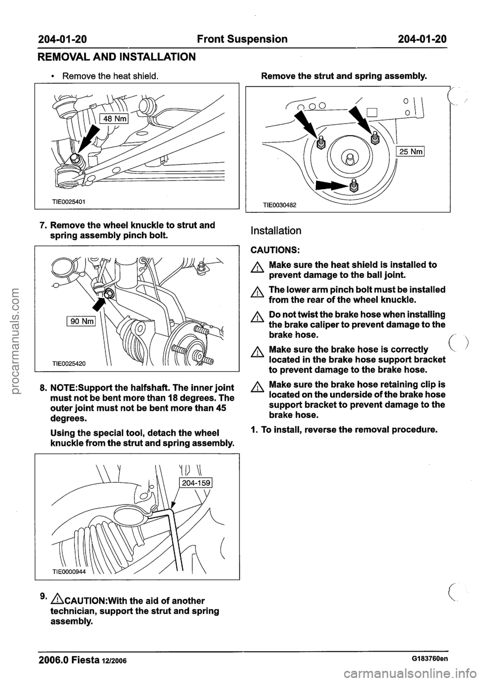
Remove the heat shield.
7. Remove the wheel knuckle to strut and
spring assembly pinch bolt.
8. N0TE:Suppot-t the halfshaft. The inner joint
must not be bent more than
I8 degrees. The
outer joint must not be bent more than
45
degrees.
Using the special tool, detach the wheel
knuckle from the strut and spring assembly.
ACAUTION:~~~~ the aid of another
technician, support the strut and spring
assembly. Remove
the strut and spring assembly.
Installation
CAUTIONS:
A Make sure the heat shield is installed to
prevent damage to the ball joint.
The lower arm pinch bolt must be installed
from the rear of the wheel knuckle.
A Do not twist the brake hose when installing
the brake caliper to prevent damage to the
brake hose.
f- ,
A Make sure the brake hose is correctly
located in the brake hose support bracket
to prevent damage to the brake hose.
A Make sure the brake hose retaining clip is
located on the underside of the brake hose
support bracket to prevent damage to the
brake hose.
I. To install, reverse the removal procedure.
2006.0 Fiesta 1~12006 GI 83760en
procarmanuals.com
Page 119 of 1226
204-01 -21 Front Suspension 204-01 -21
REMOVAL AND INSTALLATION
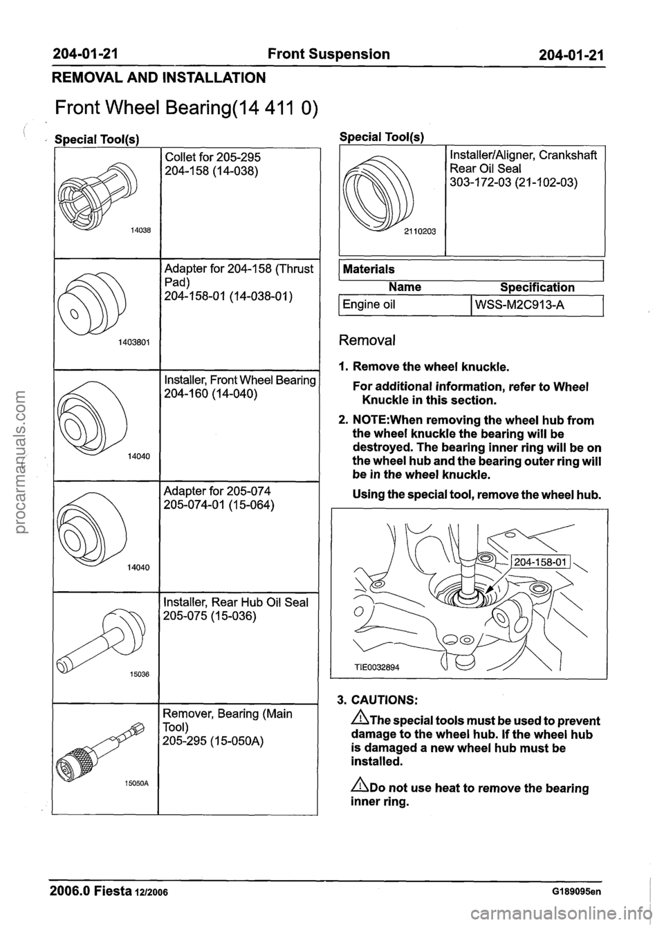
Front Wheel Bearing(l4 41 1 0)
, Special Toolls) Special Tool(s)
Adapter for 204-1 58 (Thrust
Pad)
204-1 58-01 (1 4-038-01
)
Installer, Rear Hub Oil Seal
205-075 (1 5-036)
14040
14040
Remover, Bearing (Main
Tool)
205-295 (1
5-050A)
Installer, Front Wheel Bearing
204-1 60 (1 4-040)
Adapter for 205-074
205-074-0 1 (1 5-064)
I I
Materials 1
@l 0203
I Name I Specification
Engine oil I WSS-M2C913-A
InstallerIAligner, Crankshaft
Rear Oil Seal
303-1 72-03 (2 1 -1 02-03)
Removal
I. Remove the wheel knuckle.
For additional information, refer to Wheel
Knuckle in this section.
2. N0TE:When removing the wheel hub from
the wheel knuckle the bearing will be
destroyed. The bearing inner ring will be on
the wheel hub and the bearing outer ring will
be in the wheel knuckle.
Using the special tool, remove the wheel hub.
3. CAUTIONS:
n~he special tools must be used to prevent
damage to the wheel hub. If the wheel hub
is damaged a new wheel hub must be
installed.
ADO not use heat to remove the bearing
inner ring.
2006.0 Fiesta 1212006 GI 89095en
procarmanuals.com
Page 120 of 1226
204-01 -22 Front Suspension 204101 122
REMOVAL AND INSTALLATION
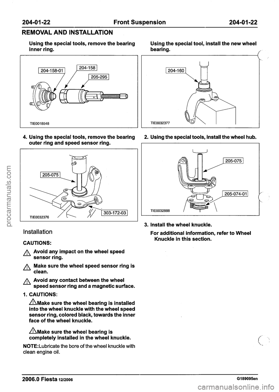
Using the special tools, remove the bearing
Using the special tool, install the new wheel
inner ring. bearing.
I"
4. Using the special tools, remove the bearing 2. Using the special tools, install the wheel hub.
outer ring and speed sensor ring.
Installation
CAUTIONS:
A Avoid any impact on the wheel speed
sensor ring.
Make sure the wheel speed sensor ring is
clean.
A Avoid any contact between the wheel
speed sensor ring and a magnetic surface.
1. CAUTIONS:
n~ake sure the wheel bearing is installed
into the wheel knuckle with the wheel speed
sensor ring, colored black, towards the inner
face of the wheel knuckle.
n~ake sure the wheel bearing is
completely installed in the wheel knuckle.
N0TE:Lubricate the bore of the wheel knuckle with
clean engine oil.
3. Install the wheel knuckle.
For additional information, refer to Wheel
Knuckle in this section.
--
2006.0 Fiesta 1212006 GI 89095en
procarmanuals.com