light FORD FIESTA 2007 Owner's Manual
[x] Cancel search | Manufacturer: FORD, Model Year: 2007, Model line: FIESTA, Model: FORD FIESTA 2007Pages: 1226, PDF Size: 61.26 MB
Page 192 of 1226
206-00-20 Brake System - General Information 206=00-20
DIAGNOSIS AND TESTING
TEST CONDITIONS
DETAILSIRESULTSIACTIONS
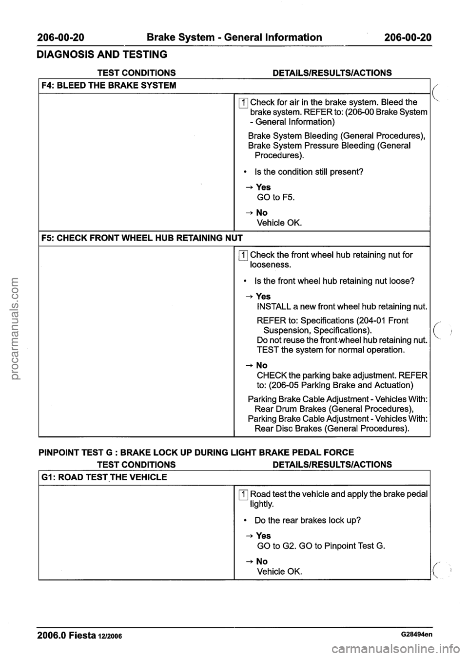
F4: BLEED THE BRAKE SYSTEM
rn Check for air in the brake system. Bleed the
brake system. REFER to: (206-00 Brake System
- General lnformation)
Brake System Bleeding (General Procedures),
Brake System Pressure Bleeding (General Procedures)
.
Is the condition still present?
+ Yes
GO to F5.
+ No
Vehicle OK.
F5: CHECK FRONT WHEEL HUB RETAINING NUT
Check the front wheel hub retaining nut for
looseness.
Is the front wheel hub retaining nut loose?
+ Yes
INSTALL a new front wheel hub retaining nut.
REFER to: Specifications (204-01 Front
Suspension, Specifications).
Do not reuse the
frontwheel hub retaining nut.
TEST the system for normal operation.
+ No
CHECK the parking bake adjustment. REFER
to: (206-05 Parking Brake and Actuation)
Parking Brake Cable Adjustment
- Vehicles With:
Rear Drum Brakes (General Procedures),
Parking Brake Cable Adjustment
- Vehicles With:
Rear Disc Brakes (General Procedures).
PINPOINT TEST G
: BRAKE LOCK UP DURING LIGHT BRAKE PEDAL FORCE
TEST CONDITIONS
DETAILSIRESULTSIACTIONS
I GI : ROAD TEST-THE VEHICLE I
Road test the vehicle and apply the brake pedal
lightly.
Do the rear brakes lock up?
+ Yes
GO to G2. GO to Pinpoint Test G.
+ No
Vehicle OK.
2006.0 Fiesta 12/2006 G28494en
procarmanuals.com
Page 196 of 1226
206-00-24 Brake System - General Information 206-00-24
DIAGNOSIS AND TESTING
TEST CONDITIONS DETAILSIRESU LTSIACTIONS
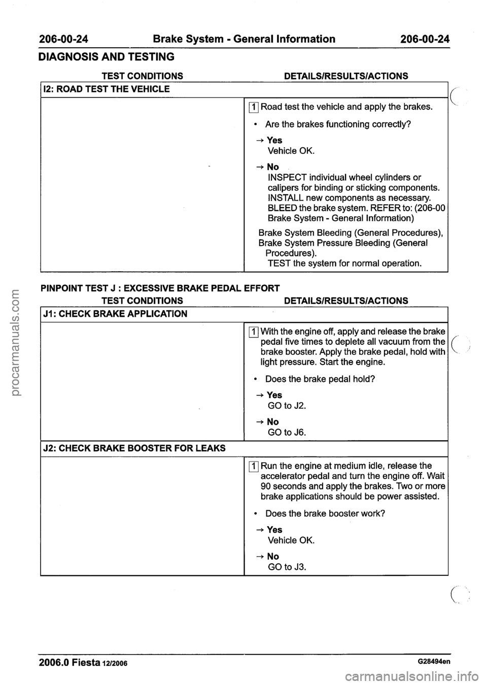
12: ROAD TEST THE VEHICLE
rn Road test the vehicle and apply the brakes.
Are the brakes functioning correctly?
-+ Yes
Vehicle OK.
+ No
INSPECT individual wheel cylinders or
calipers for binding or sticking components.
INSTALL new components as necessary.
BLEED the brake system. REFER to: (206-00
Brake System
- General Information)
Brake System Bleeding (General Procedures),
Brake System Pressure Bleeding (General Procedures).
TEST the system for normal operation.
PINPOINT TEST J
: EXCESSIVE BRAKE PEDAL EFFORT
TEST CONDITIONS
DETAILSIRESULTSIACTIONS
J1: CHECK BRAKE APPLICATION
With the engine off, apply and release the brake
pedal five times to deplete all vacuum from the
brake booster. Apply the brake pedal, hold with
light pressure. Start the engine.
Does the brake pedal hold?
+ Yes
GO to J2.
+ No
GO to J6.
52: CHECK BRAKE BOOSTER FOR LEAKS
rn Run the engine at medium idle, release the
accelerator pedal and turn the engine off. Wait
90 seconds and apply the brakes. Two or more
brake applications should be power assisted.
Does the brake booster work?
+ Yes
Vehicle OK.
-+ No
GO to
J3.
2006.0 Fiesta 1212006 G28494en
procarmanuals.com
Page 201 of 1226

206-00-29 Brake System - General Information 206-00-29
DIAGNOSIS AND TESTING
and repair the external leak. If the fluid level drops
and no external leak can be found, check for a
brake master cylinder bore end seal leak.
Brake System Check
Brake Pedal Reserve Check
Where a low brake pedal or the feel of a
bottomed-out condition exists, check for brake
pedal reserve.
1. Operate the engine at idle with the transaxle in
NEUTRAL.
2. Apply the brake pedal lightly three or four times.
3. Allow 15 seconds for vacuum to replenish the
brake booster.
N0TE:This increased resistance may feel like
something has bottomed out.
4. Apply the brake pedal until it stops moving
downward or an increased resistance to the
pedal travel occurs.
5. Hold the brake pedal in the applied position and
raise the engine speed to approximately 2000
rpm.
N0TE:The additional movement of the brake pedal
is the result of the increased engine intake manifold
vacuum which exerts more force on the brake
booster during engine rundown. This means that
additional stroke is available in the brake master
cylinder and the brake system is not bottoming out.
6. Release the accelerator pedal and observe that
the brake pedal moves downward as the engine
returns to idle speed.
Brake Booster Functional Test
lnspect all hoses and connections. All unused
vacuum connectors should be capped. Hoses and
their connections should be correctly secured and
in good condition with no holes and no collapsed 2.
With the transaxle in NEUTRAL, stop the engine
and apply the parking brake. Apply the brake
pedal several times to exhaust all vacuum in
the system.
3. With the engine turned off and all vacuum in the
system exhausted, apply the brake pedal and hold it down. Start the engine. If the vacuum
system is operating, the brake pedal will tend
to move downward under constant foot
pressure. If no motion is felt, the vacuum
booster system is not functioning.
4. Remove the vacuum hose from the brake
booster.
Intake manifold vacuum should be
available at the brake booster end of the hose
with the engine at idle speed and the transaxle
in NEUTRAL. Make sure that all unused vacuum
outlets are correctly capped, hose connectors
are correctly secured and vacuum hoses are in
good condition. When it is established that
manifold vacuum is available to the brake
booster, connector the vacuum hose to the
brake booster and repeat Step
3. If no
downward movement of the brake pedal is felt,
install a new brake booster. REFER to: (206-07
Power Brake Actuation)
Brake Booster
- LHD (Removal and lnstallation),
Brake Booster
- RHD (Removal and lnstallation).
5. Operate the engine a minimum of 10 seconds
at fast idle. Stop the engine and let the vehicle
stand for
10 minutes. Then, apply the brake
pedal with approximately 89
N (20 lb) force. The
pedal feel (brake application) should be the
same as that noted with the engine operating.
If the brake pedal feels hard (no power assist),
install a new vacuum check valve and then
repeat the test. If the brake pedal still feels hard,
install a new brake booster. REFER to: (206-07
Power Brake Actuation)
Brake Booster
- LHD (Removal and Installation),
Brake Booster
- RHD e em oval and installation).
If the brake pedal movement feels spongy, bleed
the brake system. REFER to: (206-00 Brake
System
- General Information)
areas. Inspect the check valve on the brake booster Brake System Bleeding (General Procedures),
for damage. Brake
System Pressure Bleeding (General
Procedures).
Brake Booster Operation Check
Brake Master Cylinder
1. Check the hydraulic brake system for leaks or
low fluid. Usually,
the first and strongest indicator of anything
wrong with the braking system is a feeling through
the brake pedal. In diagnosing the condition of the
brake master cylinder, check pedal feel as
2006.0 Fiesta 1212006 G28494en I
i
procarmanuals.com
Page 202 of 1226
Brake System - General Information
DIAGNOSIS AND TESTING
evidence of a brake concern. Check for the brake
warning indicator illumination and the fluid level in
the master cylinder reservoir.
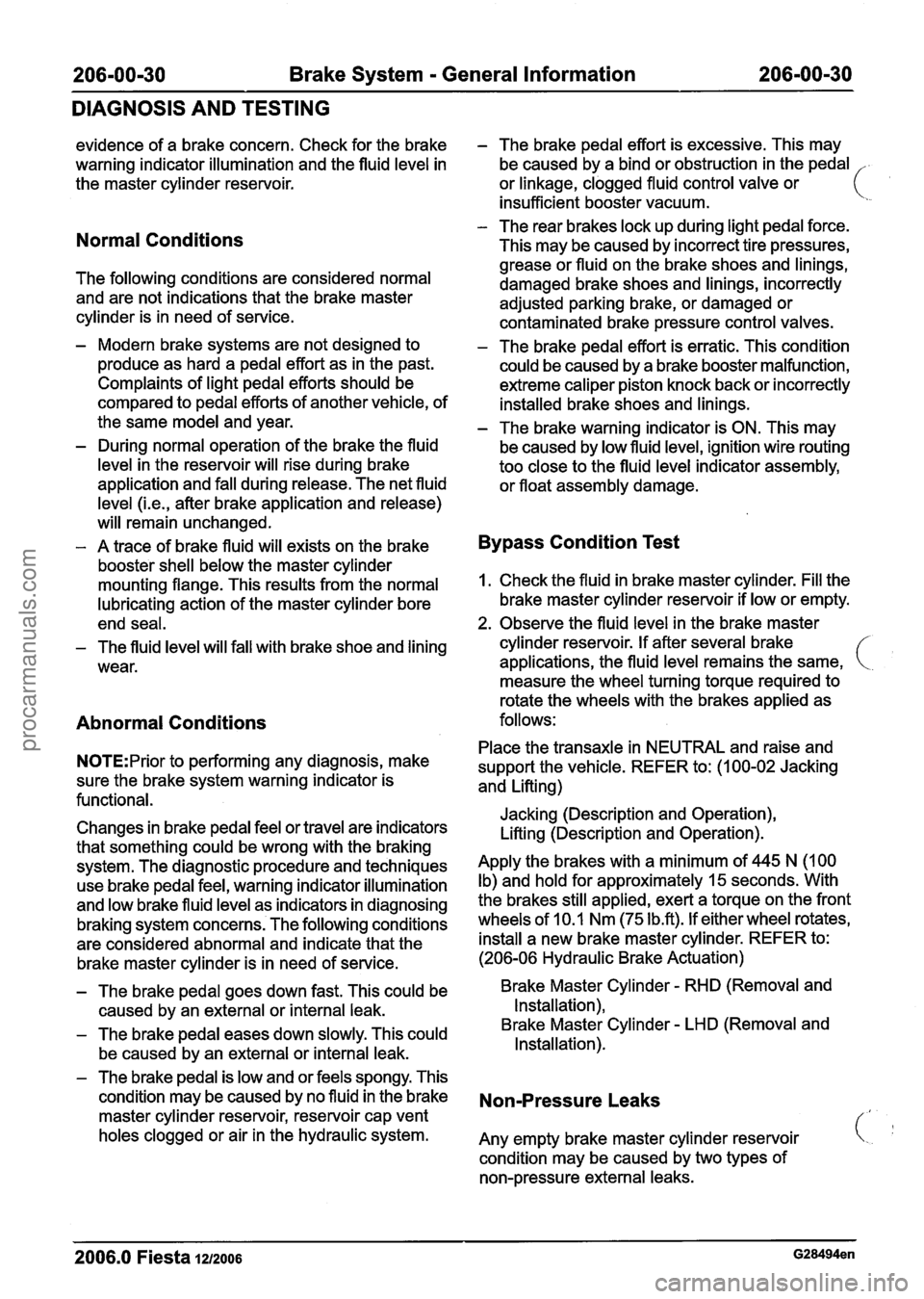
Normal Conditions
The following conditions are considered normal
and are not indications that the brake master
cylinder is in need of service.
- Modern brake systems are not designed to
produce as hard a pedal effort as in the past.
Complaints of light pedal efforts should be
compared to pedal efforts of another vehicle, of
the same model and year.
- During normal operation of the brake the fluid
level in the reservoir will rise during brake
application and fall during release. The net fluid
level
(i.e., after brake application and release)
will remain unchanged.
- A trace of brake fluid will exists on the brake
booster shell below the master cylinder
mounting flange. This results from the normal
lubricating action of the master cylinder bore
end seal.
- The fluid level will fall with brake shoe and lining
wear.
Abnormal Conditions
N0TE:Prior to performing any diagnosis, make
sure the brake system warning indicator is
functional.
Changes in brake pedal feel or travel are indicators
that something could be wrong with the braking system. The diagnostic procedure and techniques
use brake pedal feel, warning indicator illumination
and low brake fluid level as indicators in diagnosing
braking system concerns. The following conditions
are considered abnormal and indicate that the
brake master cylinder is in need of service.
- The brake pedal effort is excessive. This may
be caused by a bind or obstruction in the pedal
.
or linkage, clogged fluid control valve or ( ' insufficient booster vacuum.
- The rear brakes lock up during light pedal force.
This may be caused by incorrect tire pressures,
grease or fluid on the brake shoes and linings,
damaged brake shoes and linings, incorrectly
adjusted parking brake, or damaged or
contaminated brake pressure control valves.
- The brake pedal effort is erratic. This condition
could be caused by a brake booster malfunction,
extreme caliper piston knock back or incorrectly
installed brake shoes and linings.
- The brake warning indicator is ON. This may
be caused by low fluid level, ignition wire routing
too close to the fluid level indicator assembly,
or float assembly damage.
Bypass Condition Test
1. Check the fluid in brake master cylinder. Fill the
brake master cylinder reservoir if low or empty.
2. Observe the fluid level in the brake master
cylinder reservoir. If after several brake
applications, the fluid level remains the same,
measure the wheel turning torque required to
rotate the wheels with the brakes applied as
follows:
Place the transaxle in NEUTRAL and raise and
support the vehicle. REFER to: (1 00-02 Jacking
and Lifting)
Jacking (Description and Operation),
Lifting (Description and Operation).
Apply the brakes with a minimum of 445 N (100
Ib) and hold for approximately 15 seconds. With
the brakes still applied, exert a torque on the front
wheels of 10.1 Nm (75
1b.R). If either wheel rotates,
install a new brake master cylinder. REFER to:
(206-06 Hydraulic Brake Actuation)
- The brake pedal goes down fast. This could be Brake Master Cylinder - RHD (Removal and
caused by an external or internal leak. Installation),
- The brake
pedal eases down slowly. This could Brake Master Cylinder - LHD
(Removal and
be caused by an external or internal leak. Installation).
- The
brake pedal is low and or feels spongy. This
condition may be caused by no fluid in the brake
Non-Pressure Leaks master cylinder reservoir, reservoir cap vent
holes clogged or air in the hydraulic system.
Any empty brake master cylinder reservoir
condition may be caused by two types of
non-pressure external leaks.
2006.0 Fiesta 1212006
procarmanuals.com
Page 358 of 1226

21 1-02-1 0 Power Steering 21 1-02-1 0
REMOVAL AND INSTALLATION
Power Steering Pump - 2.OL Duratec-HE (M14)
f
I I Remover, Power Steering I
1 I Installer, Camshaft Pulley 1
7 I Removerllnstaller, Cooling I
1. Remove the right-hand headlamp assembly.
For additional information, refer to:
Headlamp Assembly (41 7-01 Exterior
Lighting, Removal and Installation).
2. Remove the accessory drive belt.
For additional information, refer to:
Accessory Drive Belt
- 2.OL Duratec-HE
(M14) (303-05 Accessory Drive, Removal
and Installation).
I
3. Detach the power steering pump to steering
, gear pressure line from the intake manifold. I
1 4. Lower the vehicle.
5. Remove the components in the order
indicated in the following
illustration(s) and
table(s).
2006.0 Fiesta 1212006 G428496en
procarmanuals.com
Page 368 of 1226
21 1-02-20 Power Steering 211 -02-20
REMOVAL AND INSTALLATION
Power Steering Pump to Steering Gear Pressure Line - 2.OL
Duratec-HE (M14) RHD
Special Tool(s)
I
- -
I Remover, Power Steering I
General Equipment 3.
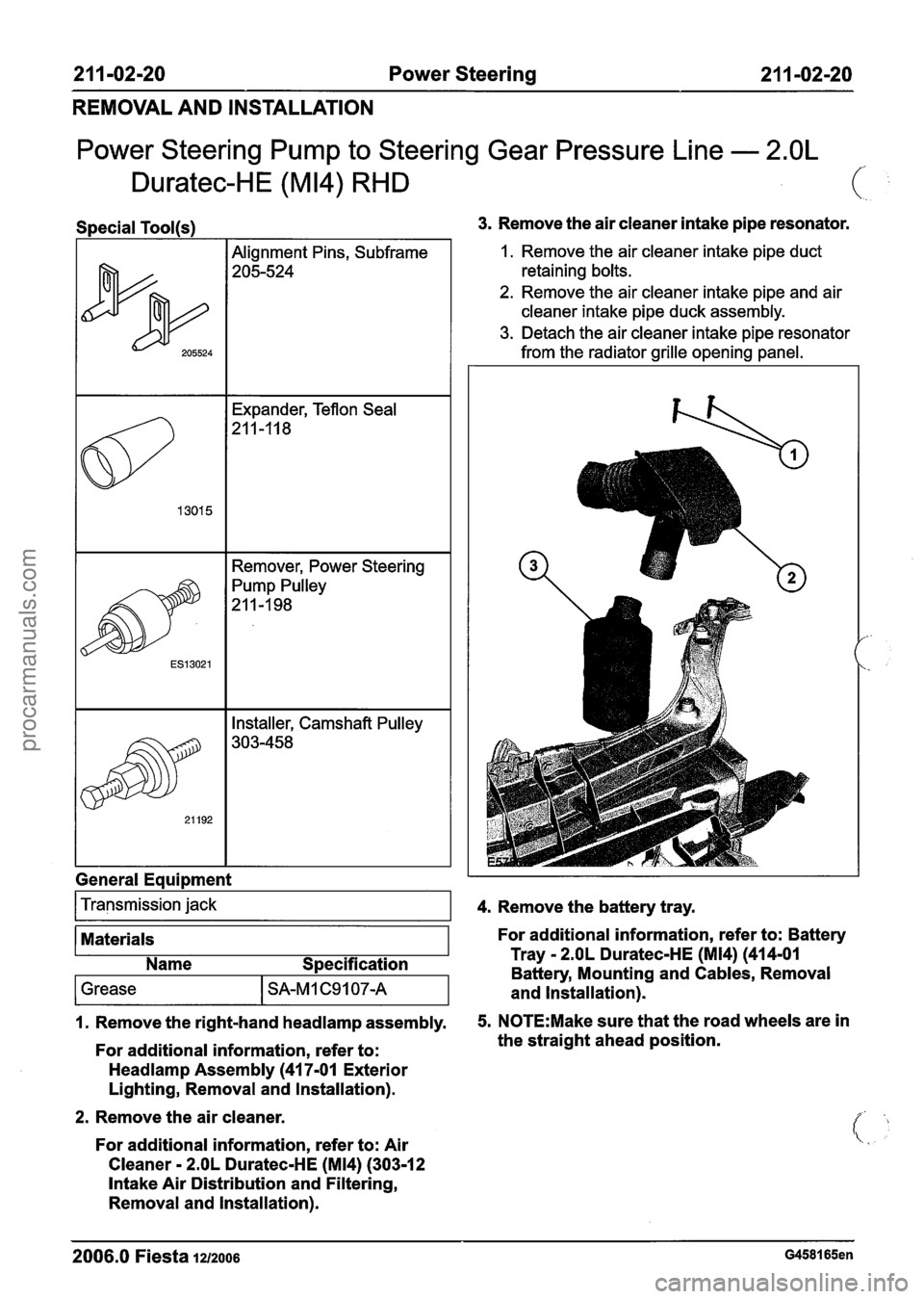
Remove the air cleaner intake pipe resonator.
1. Remove the air cleaner intake pipe duct
retaining bolts.
2. Remove the air cleaner intake pipe and air
cleaner intake pipe duck assembly.
3. Detach the air cleaner intake pipe resonator
from the radiator grille opening panel.
Transmission jack
1. Remove the right-hand headlamp assembly. 5. N0TE:Make sure that the road wheels are in
For additional information, refer to: the
straight ahead position.
4.
Remove the battery tray.
Materials
Headlamp Assembly (41 7-01 Exterior
Lighting, Removal and Installation). For additional information, refer
to: Battery
2. Remove the air cleaner.
For additional information, refer to: Air
Cleaner
- 2.OL Duratec-HE (M14) (303-1 2
Intake Air Distribution and Filtering,
Removal and Installation).
Name
Specification Tray
- 2.OL Duratec-HE (M14) (414-01
Battery, Mounting and Cables, Removal
2006.0 Fiesta 1212006 G458165en
1 Grease I SA-M 1 C9 1 07-A and Installation).
procarmanuals.com
Page 439 of 1226
303-00-1 7 Engine System - General Information 303-00-1 7
DIAGNOSIS AND TESTING
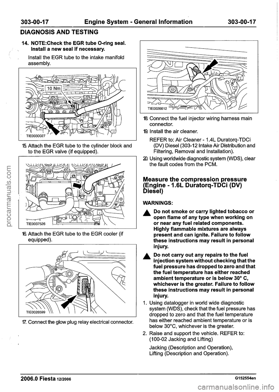
14. N0TE:Check the EGR tube O-ring seal.
Install a new seal
if necessary. I
, Install the EGR tube to the intake manifold
assembly.
18 Connect the fuel injector wiring harness main
connector.
19 Install the air cleaner.
REFER to: Air Cleaner
- 1.4L Duratorq-TDCi
15 Attach the EGR tube to the cylinder block and (DV) Diesel (303-12 Intake Air Distribution
and
to the EGR valve (if equipped). Filtering, Removal
and Installation).
Using worldwide diagnostic system (WDS), clear
the fault codes from the PCM.
Measure the compression pressure
Engine
- 1.6L Duratorq-TDCi (DV)
biesel)
WARNINGS:
A Do not smoke or carry lighted tobacco or
open flame of any type when working on
or near any fuel related components.
Highly flammable mixtures are always
16 Attach the EGR tube to the EGR cooler (if present and can ignite. Failure to follow
equipped). these instructions may result in personal
injury.
Do not carry out any repairs to the fuel
injection system without checking that the
fuel pressure has dropped to zero and that
the fuel temperature has either reached
ambient temperature or is below
30' C,
whichever is the greater. Failure to follow
these instructions may result in personal
injury.
I. Using datalogger in world wide diagnostic
system (WDS), check that the fuel pressure has
dropped to zero and that the fuel temperature
17. Connect the glow plug relay electrical connector. has
either reached ambient temperature or is
below 30°C, whichever is the greater.
2. Raise and support the vehicle. REFER to:
(1 00-02 Jacking and Lifting)
Jacking (Description and Operation),
Lifting (Description and Operation).
2006.0 Fiesta 1212006 GI 52554en
procarmanuals.com
Page 443 of 1226
303-00-21 Engine System - General Information 303-00-21
DIAGNOSIS AND TESTING
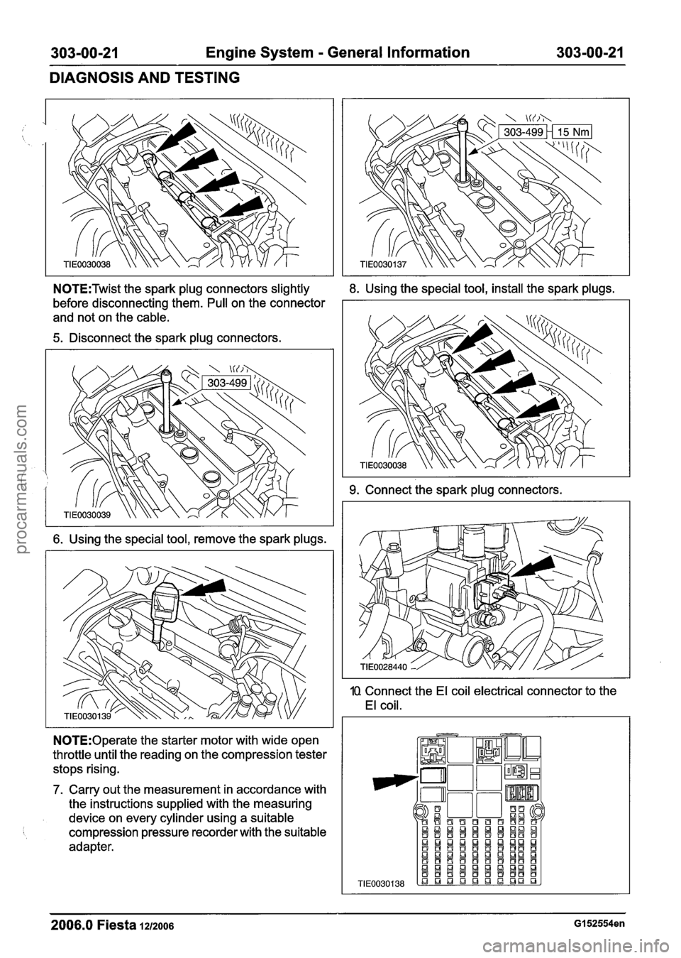
N0TE:Twist the spark plug connectors slightly 8. Using the special tool, install the spark plugs.
before disconnecting them. Pull on the connector
and not on the cable.
5. Disconnect the spark plug connectors.
6. Using the special tool, remove the spark plugs.
N0TE:Operate the starter motor with wide open
throttle until the reading on the compression tester
stops rising.
7. Carry out the measurement in accordance with
the instructions supplied with the measuring
device on every cylinder using a suitable
compression pressure recorder with the suitable
adapter.
9. Connect the spark plug connectors.
10 Connect the El coil electrical connector to the
El coil.
2006.0 Fiesta 1212006 GI 52554en
TIE0030138
QI!J!J!J~QUQI!J!J aaaaaaaaaa aBQnQIamman aBBaaaBBt3B a!JQ!JaLlnQma aaaaaaBBaf3 aaQaaQmQDa ~a~f3~B~~~B .a q q q L! q gD
procarmanuals.com
Page 444 of 1226
303-00-22 Engine System - General Information 303-00-22
DIAGNOSIS AND TESTING
11. Install the fuel pump relay.
I2 Install the air cleaner.
REFER to: Air Cleaner - 1.25L Duratec-1 6V
(Sigma)/l.4L Duratec-16V (Sigma)/l .6L
Duratec-I 6V (Sigma) (303-1 2 Intake Air
Distribution and
Filtering, Removal and
Installation).
13 Using worldwide diagnostic system (WDS), clear
the fault codes from the PCM.
Measure the compression ressure
(Engine
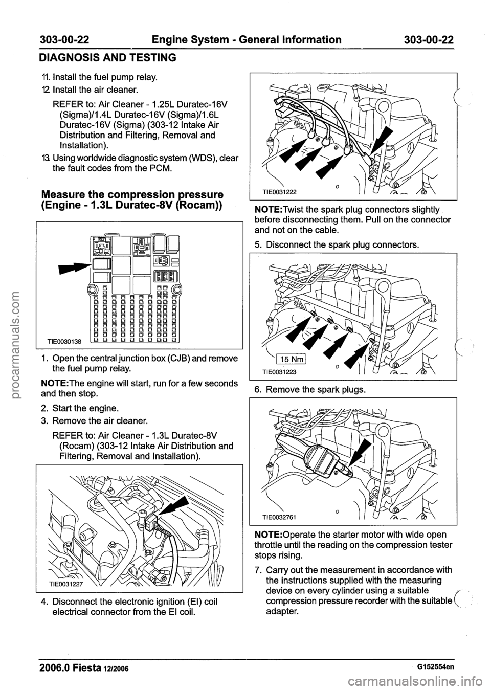
- 1 .3L Duratec-8V P Rocam)) N0TE:Twist the spark plug connectors slightly
1. Open the
central junction box (CJB) and remove
the
fuel pump relay.
before disconnecting them. Pull on the connector
and not on the
cable.
5. Disconnect the spark plug connectors.
N0TE:The engine will start, run for a few seconds
and then stop. 6. Remove the spark plugs.
2. Start the engine.
3. Remove the air
cleaner.
REFER to: Air Cleaner - 1.3L Duratec-8V
(Rocam) (303-12 Intake Air Distribution and
Filtering, Removal and Installation).
N0TE:Operate the starter motor with wide open
throttle until the reading on the compression tester
stops rising.
7. Carry out the measurement in accordance with
the instructions
supplied with the measuring
device on every
cylinder using a suitable
4. Disconnect the electronic ignition (El) coil compression pressure recorder
with the suitable (:
electrical connector from the El coil. adapter.
2006.0 Fiesta 1212006 GI 52554en
procarmanuals.com
Page 446 of 1226
303-00-24 Engine System - General Information 303-00-24
DIAGNOSIS AND TESTING
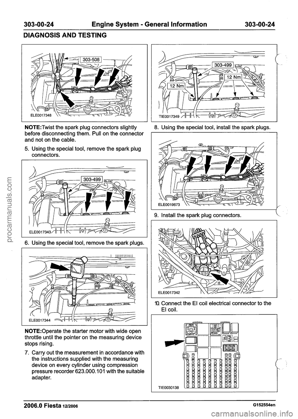
N0TE:Twist the spark plug connectors slightly
before disconnecting them. Pull on the connector
and not on the cable.
5. Using the special tool, remove the spark plug
connectors.
6. Using the special tool, remove the spark plugs.
N0TE:Operate the starter motor with wide open
throttle until the pointer on the measuring device stops rising.
7. Carry out the measurement in accordance with
the instructions supplied with the measuring
device on every cylinder using compression
pressure recorder 623.000.1 01 with the suitable
adapter.
8. Using the special tool, install the spark plugs.
9. Install the spark plug connectors. k
1Q Connect the El coil electrical connector to the
El coil.
TIE
2006.0 Fiesta 1212006 GI 52554en
procarmanuals.com