light FORD FIESTA 2007 Repair Manual
[x] Cancel search | Manufacturer: FORD, Model Year: 2007, Model line: FIESTA, Model: FORD FIESTA 2007Pages: 1226, PDF Size: 61.26 MB
Page 931 of 1226
303-1 4-7 Electronic Engine Controls 303-1 4-7
DESCRIPTION AND OPERATION
Function The throttle flap position is adjusted and monitored
in a closed control loop. The TP sensor provides
I A CAUTI0N:The throttle control unit (TCU)
the PCM with the information on the actual position
must not be dismantled. No adjustments
of the throttle flap.
or repairs can be made to the TCU.
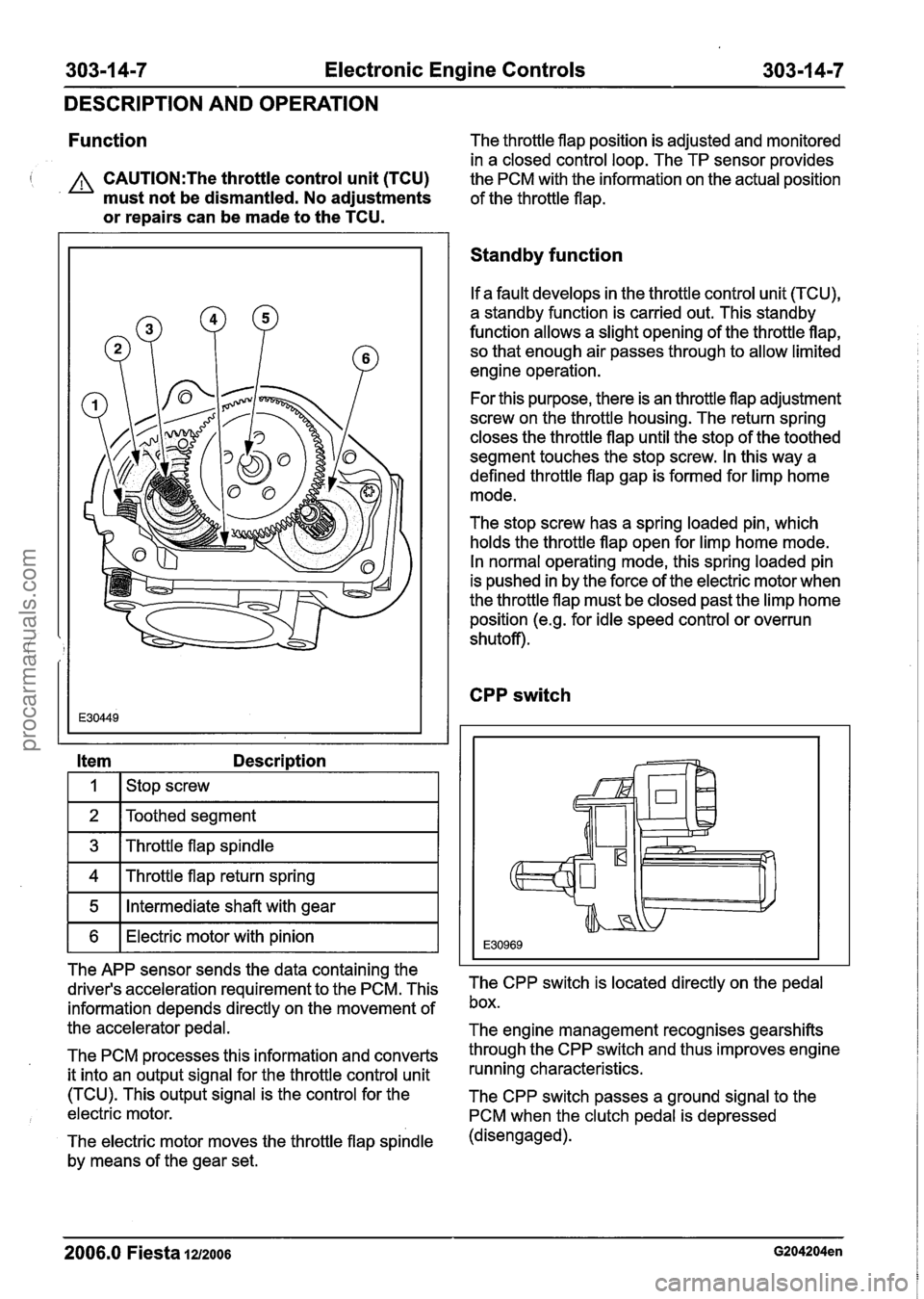
Item Description
I I I stop screw I
1 2 IToothed segment I
1 3 1 Throttle flap spindle I
1 4 1 Throttle flap return spring I
1 5 1 Intermediate shaft with gear I
1 6 1 Electric motor with pinion I
The APP sensor sends the data containing the
driver's acceleration requirement to the PCM. This
information depends directly on the movement of
the accelerator pedal.
The PCM processes this information and converts
it into an output signal for the throttle control unit
(TCU). This output signal is the control for the
electric motor.
The electric motor moves the throttle flap spindle
by means of the gear set.
Standby function
If a fault develops in the throttle control unit (TCU),
a standby function is carried out. This standby
function allows a slight opening of the throttle flap, so that enough air passes through to allow limited
engine operation.
For this purpose, there is an throttle flap adjustment
screw on the throttle housing. The return spring
closes the throttle flap until the stop of the toothed
segment touches the stop screw. In this way a
defined throttle flap gap is formed for limp home
mode.
The stop screw has a spring loaded pin, which
holds the throttle flap open for limp home mode.
In normal operating mode, this spring loaded pin
is pushed in by the force of the electric motor when
the throttle flap must be closed past the limp home
position
(e.g. for idle speed control or overrun
shutoff).
CPP switch
The CPP switch is located directly on the pedal
box.
The engine management recognises gearshifts
through the CPP switch and thus improves engine
running characteristics.
The CPP switch passes a ground signal to the
PCM when the clutch pedal is depressed
(disengaged).
2006.0 Fiesta 1212006 G204204en
procarmanuals.com
Page 990 of 1226
Automatic Transmission/Transaxle -
Vehicles With: 4-Speed Automatic
307-01 -30 Transmission (AW81-40) 307-01 -30
DESCRIPTION AND OPERATION
The transmission control unit can be diagnosed
with WDS via the DLC.
Gearshift strategies
Gearshift control
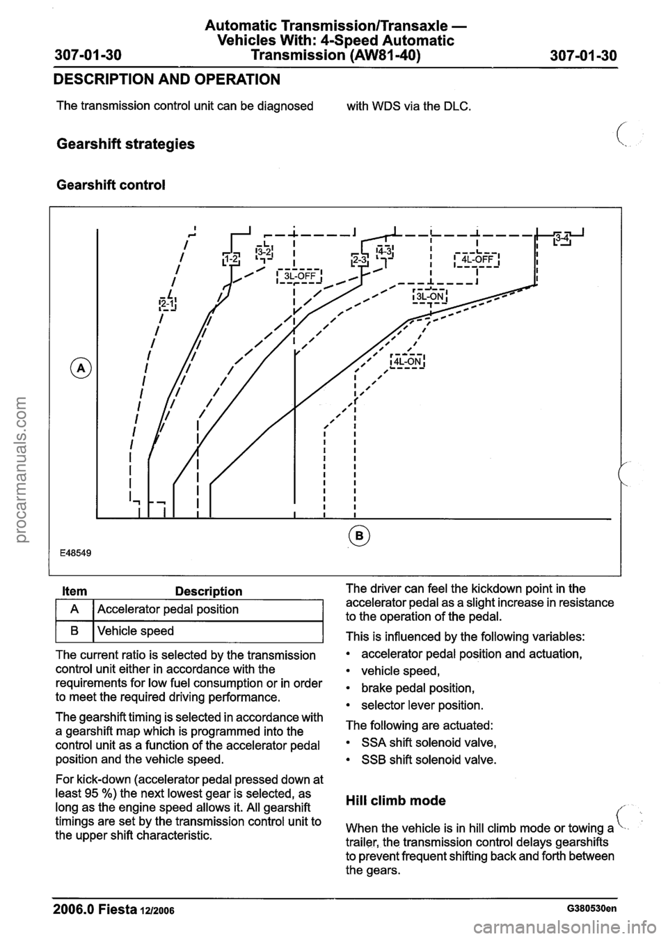
I A I Accelerator pedal position I
I B I vehicle speed 1
The current ratio is selected by the transmission
control unit either in accordance with the
requirements for low fuel consumption or in order
to meet the required driving performance.
The gearshift timing is selected in accordance with
a gearshift map which is programmed into the
control unit as a function of the accelerator pedal
position and the vehicle speed.
For kick-down (accelerator pedal pressed down at
least
95 %) the next lowest gear is selected, as
long as the engine speed allows it. All gearshift
timings are set by the transmission control unit to
the upper shift characteristic. The driver can feel the
kickdown point
in the
accelerator pedal as a slight increase in resistance
to the operation of the pedal.
This is influenced by the following variables:
accelerator pedal position and actuation,
vehicle speed,
brake pedal position,
selector lever position.
The following are actuated:
SSA shift solenoid valve,
SSB shift solenoid valve.
Hill climb mode
When the vehicle is in hill climb mode or towing a
trailer, the transmission control delays gearshifts
to prevent frequent shifting back and forth between
the gears.
2006.0 Fiesta 1u2oos
procarmanuals.com
Page 1020 of 1226
Automatic Transmission/Transaxle -
Vehicles With: 4-Speed Automatic
307-01 -60 Transmission
(AW81-40) 307-01 -60
IN-VEHICLE REPAIR
Turbine Shaft Speed (TSS) Sensor
Removal
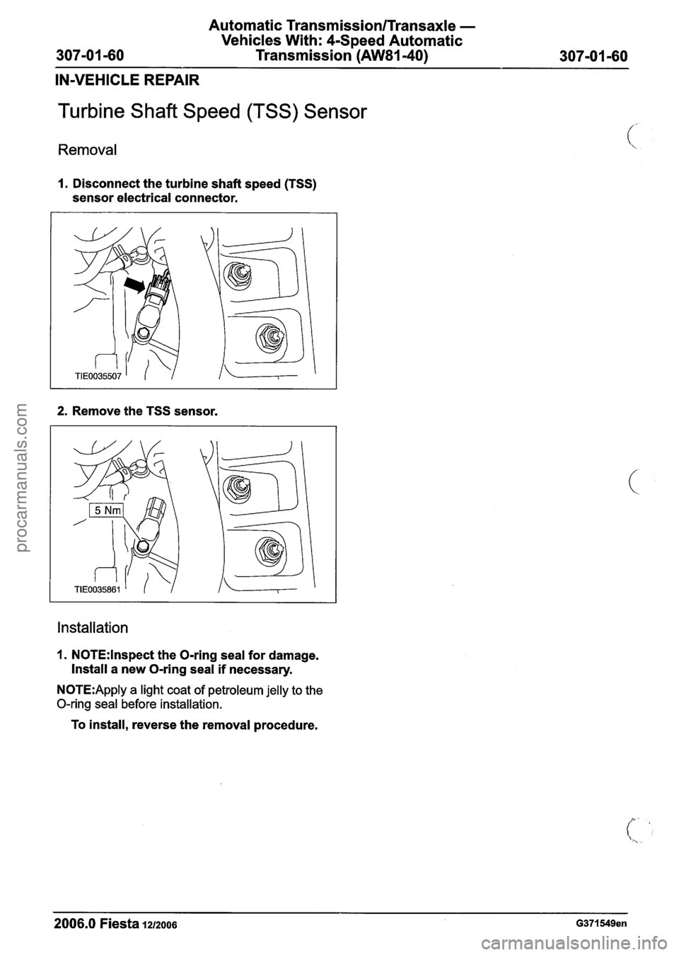
1. Disconnect the turbine shaft speed (TSS)
sensor electrical connector.
2. Remove the TSS sensor.
Installation
1. N0TE:lnspect the O-ring seal for damage.
Install
a new O-ring seal if necessary.
N0TE:Apply a light coat of petroleum jelly to the
O-ring seal before installation.
To install, reverse the removal procedure.
2006.0 Fiesta 1212006 G371549en
procarmanuals.com
Page 1021 of 1226
Automatic Transmission/Transaxle -
Vehicles With: 4-Speed Automatic
307-01 -61 Transmission (AW81-40) 307-01 -61 --
IN-VEHICLE REPAIR
Vehicle Speed Sensor (VSS)
Removal
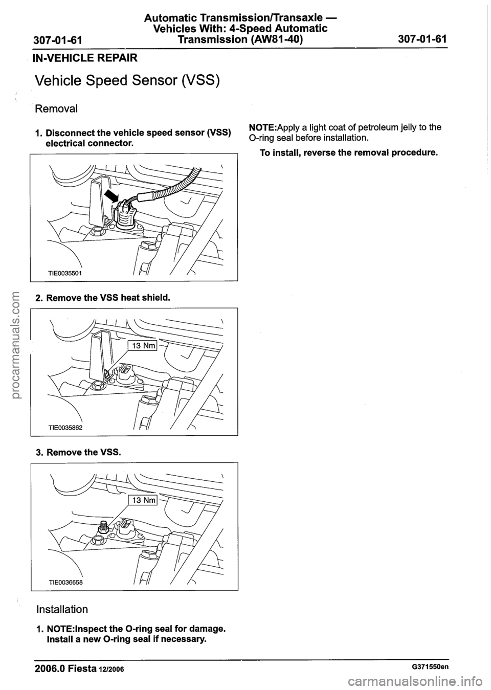
N0TE:Apply a light coat of petroleum jelly to the 1. Disconnect the vehicle speed sensor (VSS) O-ring seal before installation. electrical connector.
2. Remove the VSS heat shield.
3. Remove the VSS.
Installation
1. N0TE:lnspect the O-ring seal for damage.
Install a new O-ring seal if necessary. To
install, reverse the removal procedure.
2006.0 Fiesta 1212006 G371550en
procarmanuals.com
Page 1076 of 1226
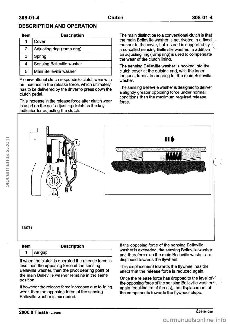
308-01 4 Clutch 308-01 -4
DESCRIPTION AND OPERATION
Item Description
I I 1 Cover I
1 2 I Adjusting ring (ramp ring) I
1 3 1 Spring I
1 4 1 Sensing Belleville washer I
r5 1 Main Belleville washer I
A conventional clutch responds to clutch wear with
an increase in the release force, which ultimately
has to be delivered by the driver to press down the
clutch pedal.
This increase in the release force after clutch wear
is used on the self-adjusting clutch as the key
indicator for adjusting the clutch. The main
distinction to a conventional clutch is that
the main Belleville washer is not riveted in a fixed
-
manner to the cover, but instead is supported by (
a so-called sensing Belleville washer. In addition
an adjusting ring (ramp ring) is used to compensate
the wear of the clutch lining.
The sensing Belleville washer is hooked into the
clutch cover at the outside and, with the inner
tongues, forms the bearing for the main Belleville
washer.
The sensing Belleville washer is designed to deliver
a slightly greater opposing force under normal
conditions than the maximum required release
force.
Item Description
If when the clutch is operated the release force is
less than the opposing force of the sensing
Belleville washer, then the pivot bearing point of
the main Belleville washer remains in the same
position.
If however the release force increases due to lining
wear, then the opposing force of the sensing
Belleville washer is exceeded. If the
opposing force of the sensing Belleville
washer is exceeded, the sensing Belleville washer
and therefore also the main Belleville washer are
displaced towards the flywheel.
This displacement towards the flywheel has the
effect that the release force is reduced again.
Once the release force has dropped to the level of
the opposing force of the sensing Belleville washer
again (equilibrium of forces), the displacement of
the components towards the flywheel stops.
2006.0 Fiesta lazoos ~251010en
procarmanuals.com
Page 1144 of 1226
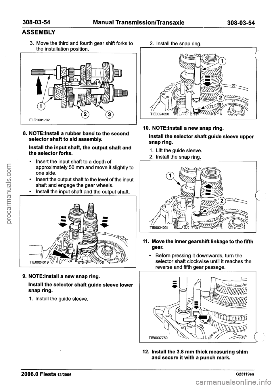
308-03-54 Manual Transmission/Transaxle 308-0344
ASSEMBLY
3. Move the third and fourth gear shift forks to
the installation position.
8. N0TE:lnstall a rubber band to the second
selector shaft to aid assembly.
2. lnstall the snap ring.
10. N0TE:lnstall a new snap ring.
lnstall the selector shaft guide sleeve upper
snap ring.
- lnstall the input shaft, the output shaft and
the selector forks. 1. Lift the guide sleeve.
2. lnstall the snap rina.
Insert the input shaft to a depth of I
approximately 50 mm and move it slightly to
one side.
Insert the output shaft to the level of the input
shaft and engage the gear wheels.
lnstall the input shaft and the output shaft.
9. N0TE:lnstall a new snap ring.
lnstall the selector shaft guide sleeve lower
snap ring.
1. lnstall the guide sleeve.
11. Move the inner gearshift linkage to the fifth
gear.
Before pressing it downwards, turn the
selector shaft clockwise until it reaches the
reverse and fifth gear passage.
12. lnstall the 3.8 mm thick measuring shim
and secure
it with a punch mark.
2006.0 Fiesta 1212006 G23119en
procarmanuals.com
Page 1147 of 1226
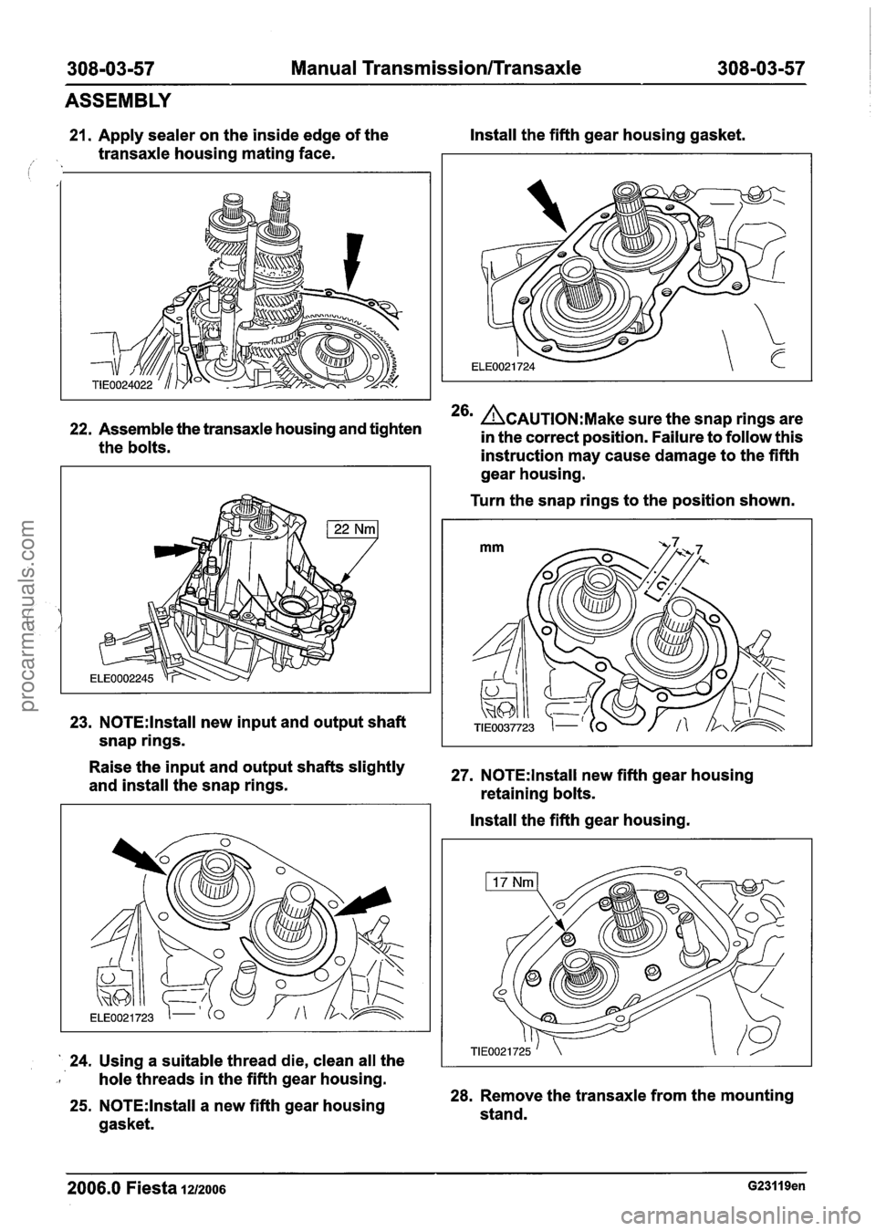
308-03-57 Manual Transmission/Transaxle 308-03-57 I I
ASSEMBLY
21. Apply sealer on the inside edge of the Install
the fifth gear housing gasket.
1. transaxle housing mating face.
22. Assemble the transaxle housing and tighten 26m ACAUTION:M~~~ sure the snap rings are
in the correct position. Failure to follow this
the bolts.
instruction may cause damage to the fifth
23. N0TE:lnstall new input and output shaft
snap rings. gear
housing.
Turn the snap rings to the position shown.
Raise the and shafts 'lightly 27. NOTE:lnstall new fifth gear housing
and install the snap rings.
retaining bolts.
' 24. Using a suitable thread die, clean all the Install
the fifth gear housing.
-I hole threads in the fifth gear housing.
25. N0TE:lnstall a new fifth gear housing 28. Remove the transaxle from the mounting
stand.
gasket.
2006.0 Fiesta 1212006 G23119en
procarmanuals.com
Page 1171 of 1226
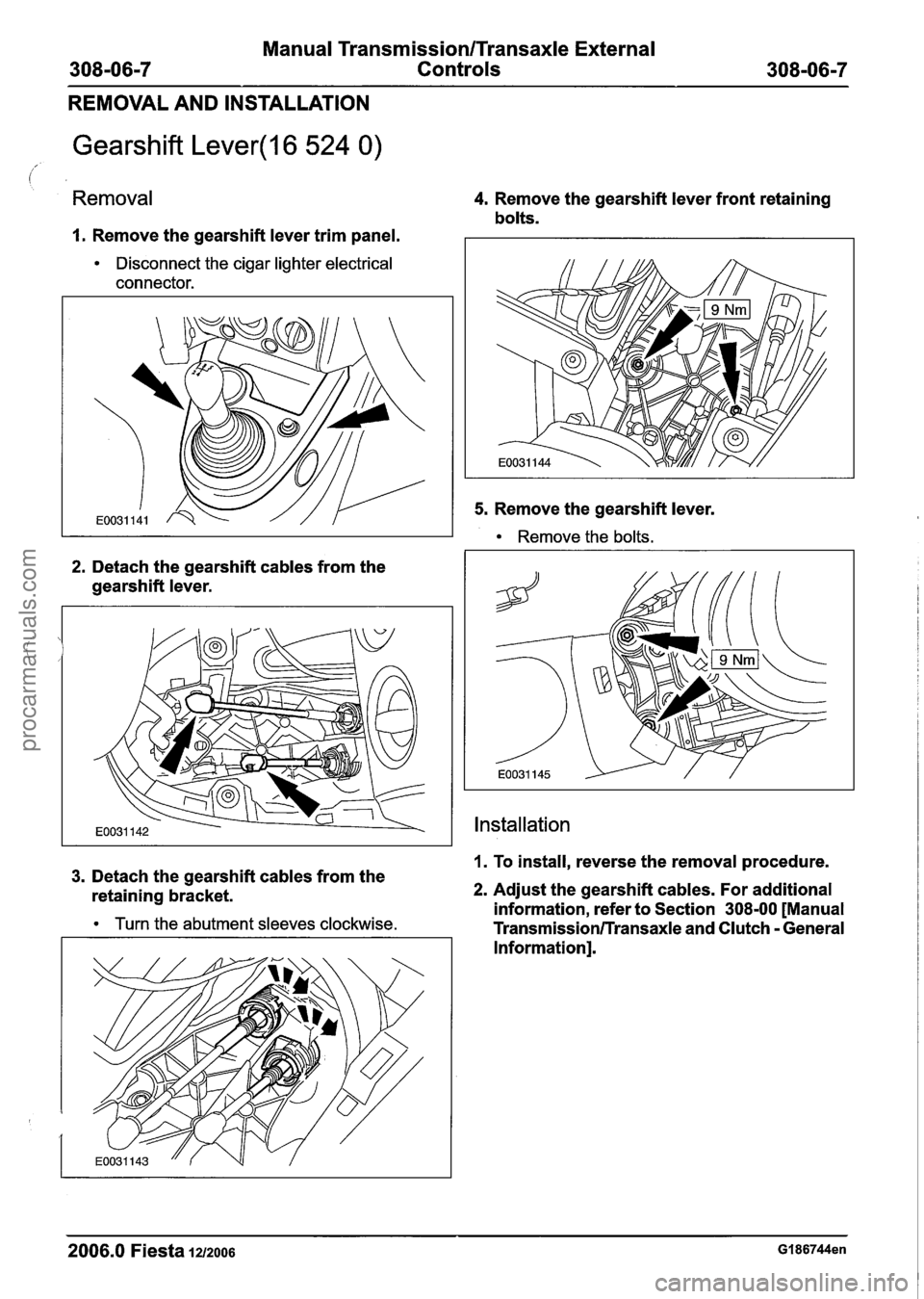
Manual Transmission/Transaxle External
Controls
REMOVAL AND INSTALLATION
Gearshift Lever(l6 524 0)
Removal
I. Remove the gearshift lever trim panel.
Disconnect the cigar lighter electrical
connector.
2. Detach the gearshift cables from the
gearshift lever.
4. Remove the gearshift lever front retaining
bolts.
5. Remove the gearshift lever.
Remove the bolts.
Installation
1. To install, reverse the removal procedure. 3. Detach the gearshift cables from the
retaining bracket. 2. Adjust the gearshift cables. For additional
information, refer to Section
308-00 [Manual Turn the abutment sleeves clockwise. Transmission/Transaxle and Clutch - General
Information].
2006.0 Fiesta 1212006 GI 86744en
procarmanuals.com
Page 1189 of 1226
31 0-00-3 Fuel System - General Information 31 0-00-3
GENERAL PROCEDURES
/'
Fuel System Pressure Release(23 420 0)
i
Release
I. WARNINGS:
ADO not smoke or carry lighted tobacco or
open flame of any type when working on or
near any fuel related components. Highly
flammable vapors are always present and
may ignite. Failure to follow these
instructions may result in personal injury.
A~he fuel system remains pressurized for
a long time after the ignition is switched off.
The fuel pressure must be released before
attempting any repairs. Failure to follow this
instruction may result in personal injury.
Remove the fuel pump fuse.
2. Start the engine and allow to idle until the
engine stalls.
3. Crank the engine for approximately five
seconds to make sure the fuel injection
supply manifold pressure has been released.
,1 4. Install the fuel pump fuse.
2006.0 Fiesta 1212006 GI 81 91 en
procarmanuals.com
Page 1190 of 1226
31 0-00-4 Fuel System - General Information 31 0-00-4
GENERAL PROCEDURES
Fuel Tank Draining(23 551 0)
General Eaui~ment
I Fuel tank draining equipment I
Draining
WARNINGS:
A Do not smoke or carry lighted tobacco or
open flame of any type when working on
or near any fuel related components.
Highly flammable vapors are always
present and may ignite. Failure to follow
these instructions may result in personal
injury.
A The fuel system remains pressurized for a
long time after the ignition is switched off.
The fuel pressure must be relieved before
attempting any repairs. Failure to follow
these instructions may result in personal
injury.
I. Disconnect the battery ground cable. For
additional information, refer to
Section
414-01 [Battery, Mounting and
Cables].
2. Remove the fuel tank filler cap.
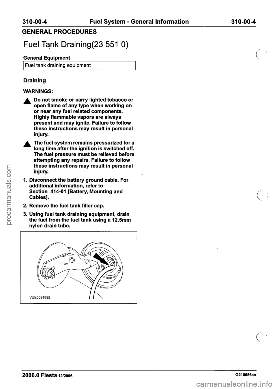
3. Using fuel tank draining equipment, drain
the fuel from the fuel tank using a
12.5mm
nylon drain tube.
2006.0 Fiesta 1212006 G210056en
procarmanuals.com