engine FORD FIESTA 2007 Workshop Manual
[x] Cancel search | Manufacturer: FORD, Model Year: 2007, Model line: FIESTA, Model: FORD FIESTA 2007Pages: 1226, PDF Size: 61.26 MB
Page 650 of 1226
303-01 B-28 Engine - 2.OL Duratec-HE (M14) 303-01 B-28
IN-VEHICLE REPAIR
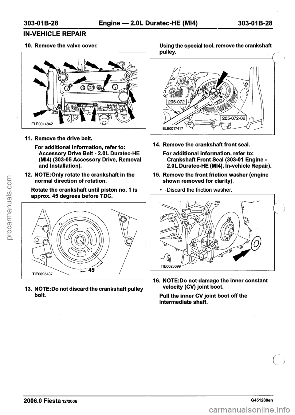
10. Remove the valve cover.
11. Remove the drive belt.
For additional information, refer to:
Accessory Drive Belt
- 2.OL Duratec-HE
(M14) (303-05 Accessory Drive, Removal
and Installation).
12.
N0TE:Only rotate the crankshaft in the
normal direction of rotation.
Rotate the crankshaft until piston no.
1 is
approx. 45 degrees before TDC. Using
the special tool, remove the crankshaft
pulley.
14. Remove the crankshaft front seal.
For additional information, refer to:
Crankshaft Front Seal (303-01 Engine
-
2.OL Duratec-HE (M14), Invehicle Repair).
15. Remove the front friction washer (engine
shown removed for clarity).
. Discard the friction washer.
16. N0TE:Do not damage the inner constant
13.
N0TE:Do not discard the crankshaft pulley velocity
(CV) joint boot.
bolt. Pull the inner CV joint boot off the
intermediate shaft.
2006.0 Fiesta 1212006 G451288en
procarmanuals.com
Page 651 of 1226

303-01 B-29 Engine - 2.OL Duratec-HE (M14) 303-01 B-29
IN-VEHICLE REPAIR
Remove and discard the CV joint boot clamp. 5. Install the special tool.
Installation 6. Raise the vehicle. For additional information,
refer to: (1 00-02 Jacking and Lifting)
1. N0TE:lnstall a new front friction washer.
Jacking (Description and Operation),
Install the front friction washer (engine
Lifting (Description and Operation).
shown removed for clarity).
7. Remove the cylinder block lower blanking
plug and install the special tool.
2. Install the crankshaft front seal.
For additional information, refer to:
8. N0TE:Only rotate the crankshaft in the
Crankshaft Front Seal (303-01 Engine - 2.OL normal direction of rotation.
Duratec-HE (M14), In-vehicle Repair).
Rotate the crankshaft using the crankshaft
3. Lower the vehicle.
pulley bolt until the crankshaft contacts the
4. N0TE:Only rotate the camshafts in the special
tool.
normal direction of rotation.
Carefully rotate the camshafts using a
spanner until the cams of cylinder no. 4 are
positioned at the valve overlap.
2006.0 Fiesta 1212006
procarmanuals.com
Page 652 of 1226
303-01 B-30 Engine - 2.OL Duratec-HE (M14) 303-01 B-30
IN-VEHICLE REPAIR
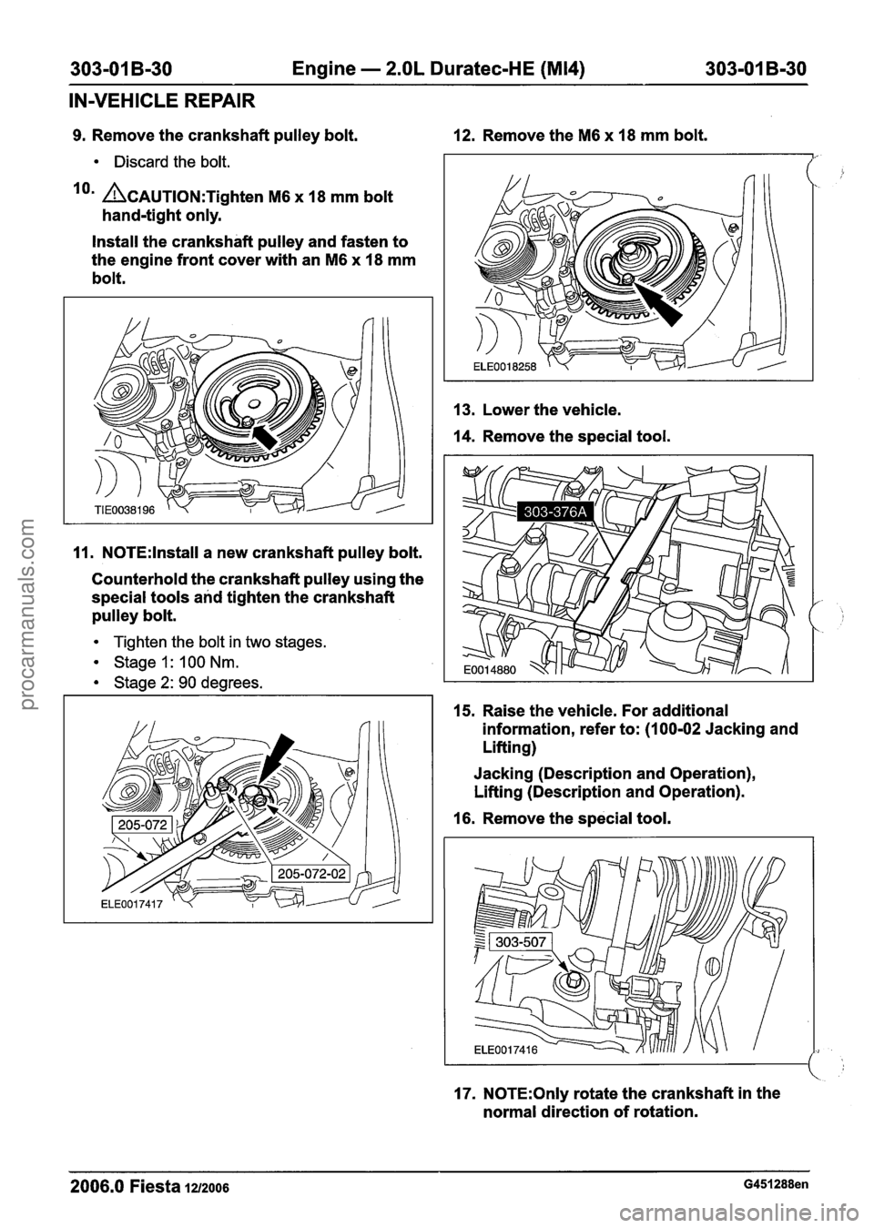
9. Remove the crankshaft pulley bolt. 12. Remove the M6 x 18 mm bolt.
Discard the bolt.
lorn ACAUTION:T~~~~~~ M6 x 18 mm bolt
hand-tight only.
Install the crankshaft pulley and fasten to
the engine front cover with an
M6 x 18 mm
bolt.
11. N0TE:lnstall a new crankshaft pulley bolt.
Counterhold the crankshaft pulley using the
special tools and tighten the crankshaft
pulley bolt.
Tighten the bolt in two stages.
Stage 1: I00 Nm.
Stage 2: 90 degrees. 13.
Lower
the vehicle.
14. Remove the special tool.
I 1 15. Raise the vehicle. For additional
information, refer to:
(100-02 Jacking and
Lifting)
Jacking (Description and Operation),
Lifting (Description and Operation).
16. Remove the special tool.
17. N0TE:Only rotate the crankshaft in the
normal direction of rotation.
2006.0 Fiesta 1212006 G451288en
procarmanuals.com
Page 653 of 1226
303-01 B-31 Engine - 2.OL Duratec-HE (M14) 303-01 B-31
IN-VEHICLE REPAIR
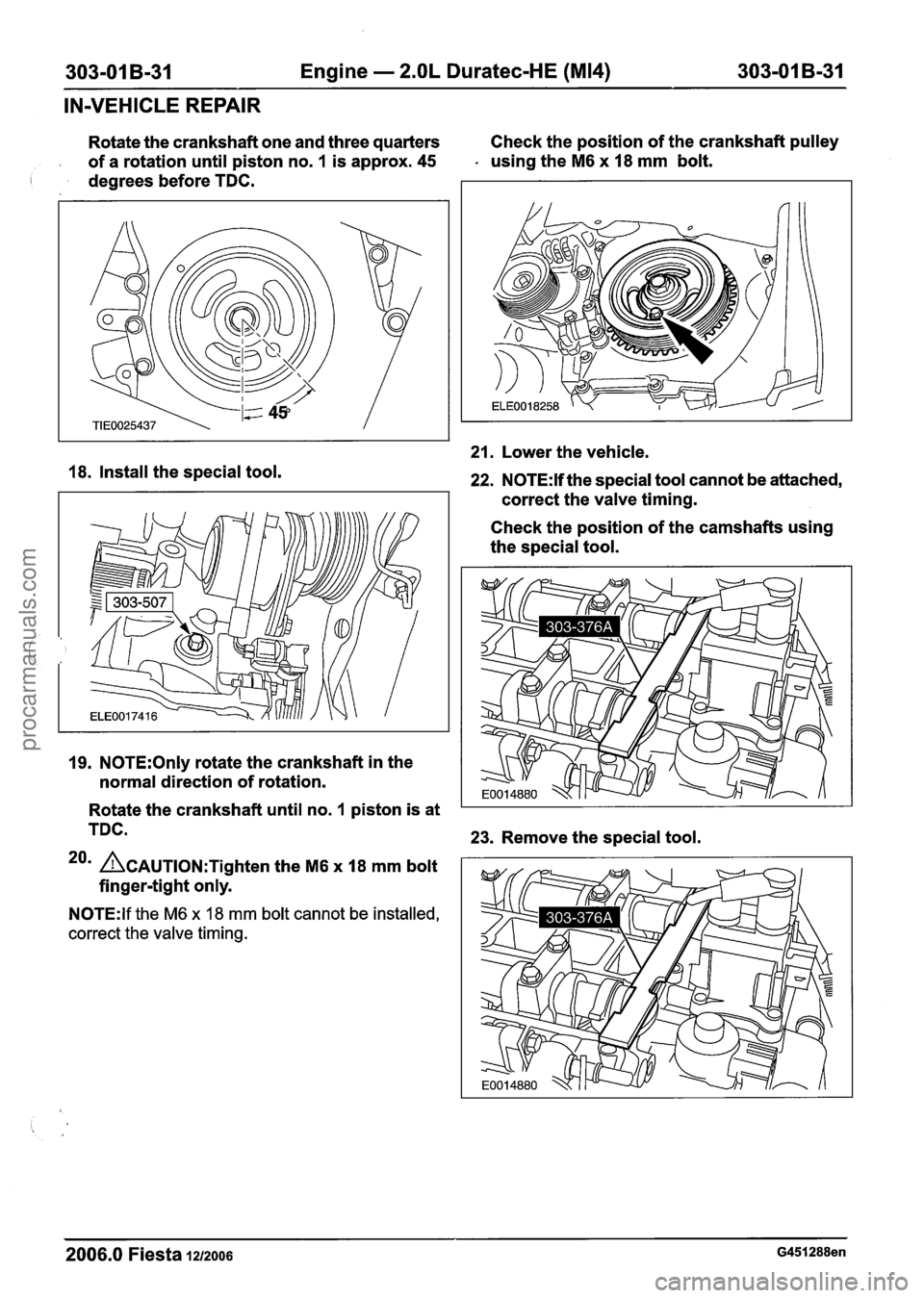
Rotate the crankshaft one and three quarters Check
the position of the crankshaft pulley
of a rotation until piston no.
1 is approx. 45 - using the M6 x 18 mm bolt.
I degrees before TDC.
18. Install the special tool.
19. N0TE:Only rotate the crankshaft in the
normal direction of rotation.
21. Lower the vehicle.
22. N0TE:H the special tool cannot be attached,
correct the valve timing.
Check the position of the camshafts using
the special tool.
Rotate the crankshaft until no.
1 piston is at
TDC.
23. Remove the special tool.
20m ~CAUTION:T~~~~~~ the M6 x 18 mrn bolt
finger-tight only.
N0TE:lf the M6 x 18 mm bolt cannot be installed,
correct the valve timing.
2006.0 Fiesta 1212006 G451288en
procarmanuals.com
Page 654 of 1226
303-01 B-32 Engine - 2.OL Duratec-HE (M14) 303-01 B-32
IN-VEHICLE REPAIR
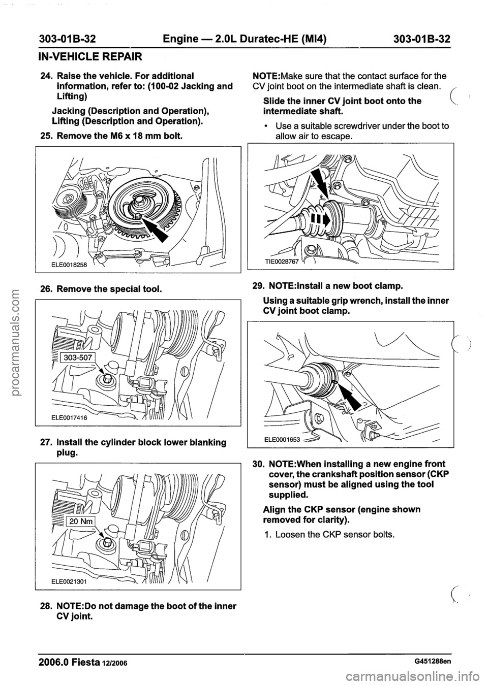
24. Raise the vehicle. For additional N0TE:Make sure that the contact surface for the
information, refer to: (100-02 Jacking and CV joint boot on the intermediate shaft is clean. ,
Lifting)
Slide the inner CV joint boot onto the
Jacking (Description and Operation),
intermediate shaft. (..
Lifting (Description and Operation). Use a suitable screwdriver under the boot to
25. Remove the M6 x 18 mm bolt. allow air to escape.
26. Remove the special tool. 29. N0TE:lnstall a
new boot clamp.
Using a suitable grip wrench, install the inner
CV joint boot clamp.
27. Install the cylinder block lower blanking
plug.
30. N0TE:When installing a new engine front
cover, the crankshaft position sensor
(CKP
sensor) must be aligned using the tool
supplied.
28.
N0TE:Do not damage the boot of the inner
CV joint. Align
the
CKP sensor (engine shown
removed for clarity).
1. Loosen the CKP sensor bolts.
2006.0 Fiesta 1212006 G451288en
procarmanuals.com
Page 655 of 1226
303-01 B-33 Engine - 2.OL Duratec-HE (M14) 303-01 B-33
IN-VEHICLE REPAIR
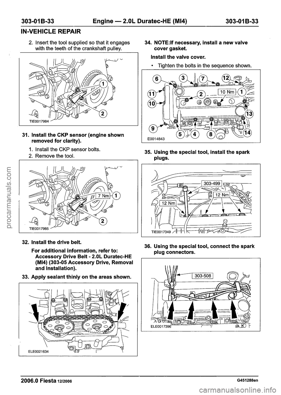
2. Insert the tool supplied so that it engages 34. N0TE:lf necessary, install a new valve
with the teeth of the crankshaft pulley. cover gasket.
31. Install the CKP sensor (engine shown
removed for clarity).
1. Install the CKP sensor bolts.
2. Remove the tool.
Install the valve cover.
Tighten the bolts in the sequence shown.
35. Using the special tool, install the spark
plugs.
. Install the drive belt.
36. Using the special tool, connect the spark
For additional information, refer to:
plug connectors.
Accessory Drive Belt
- 2.OL Duratec-HE
(M14) (303-05 Accessory Drive, Removal
and Installation).
33. Apply sealant thinly on the areas shown.
-- - -- -
2006.0 Fiesta 1212006 G451288en
procarmanuals.com
Page 656 of 1226
303-01 B-34 Engine - 2.OL Duratec-HE (M14) 303-01 B-34
IN-VEHICLE REPAIR
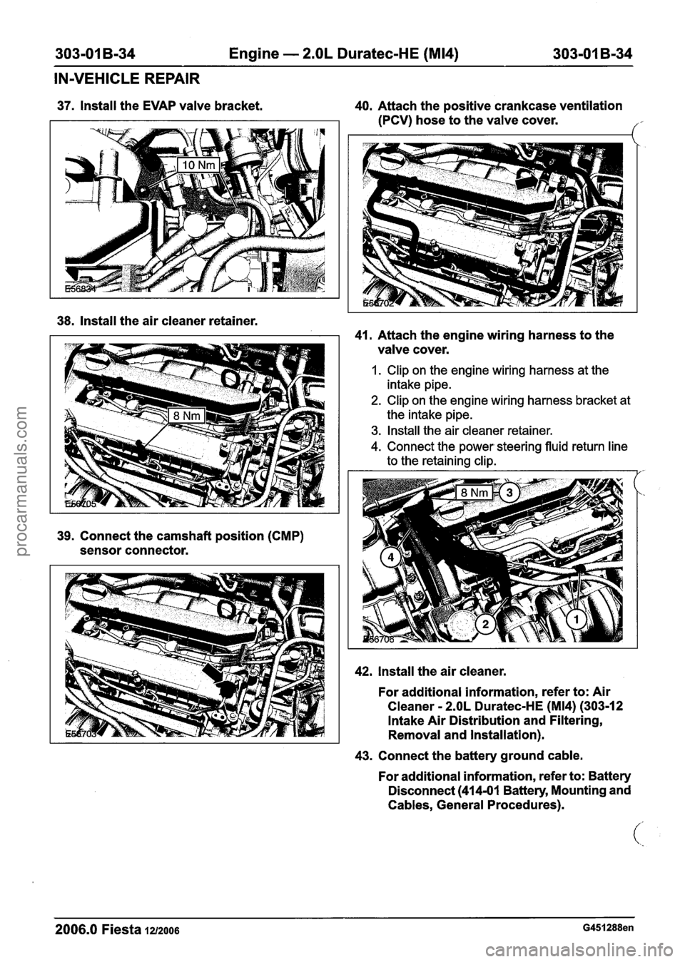
37. Install the EVAP valve bracket. 40. Attach the positive crankcase ventilation
(PCV) hose to the valve cover.
/- r.
38. Install the air cleaner retainer.
41. Attach the engine wiring harness to the
valve cover.
1. Clip on the engine wiring harness at the
intake pipe.
2. Clip on the engine wiring harness bracket at
the intake pipe.
3. Install the air cleaner retainer.
4. Connect the power. steering fluid return line
to the retaining clip.
42. Install the air cleaner.
For additional information, refer to: Air
Cleaner
- 2.OL Duratec-HE (M14) (303-12
Intake Air Distribution and Filtering,
Removal and Installation).
43. Connect the battery ground cable.
For additional information, refer to: Battery
Disconnect
(414-01 Battery, Mounting and
Cables, General Procedures).
2006.0 Fiesta 1212006 G451288en
procarmanuals.com
Page 657 of 1226
303-01 B-35 Engine - 2.OL Duratec-HE (M14) 303-01 B-35 -- - - - - -
IN-VEHICLE REPAIR
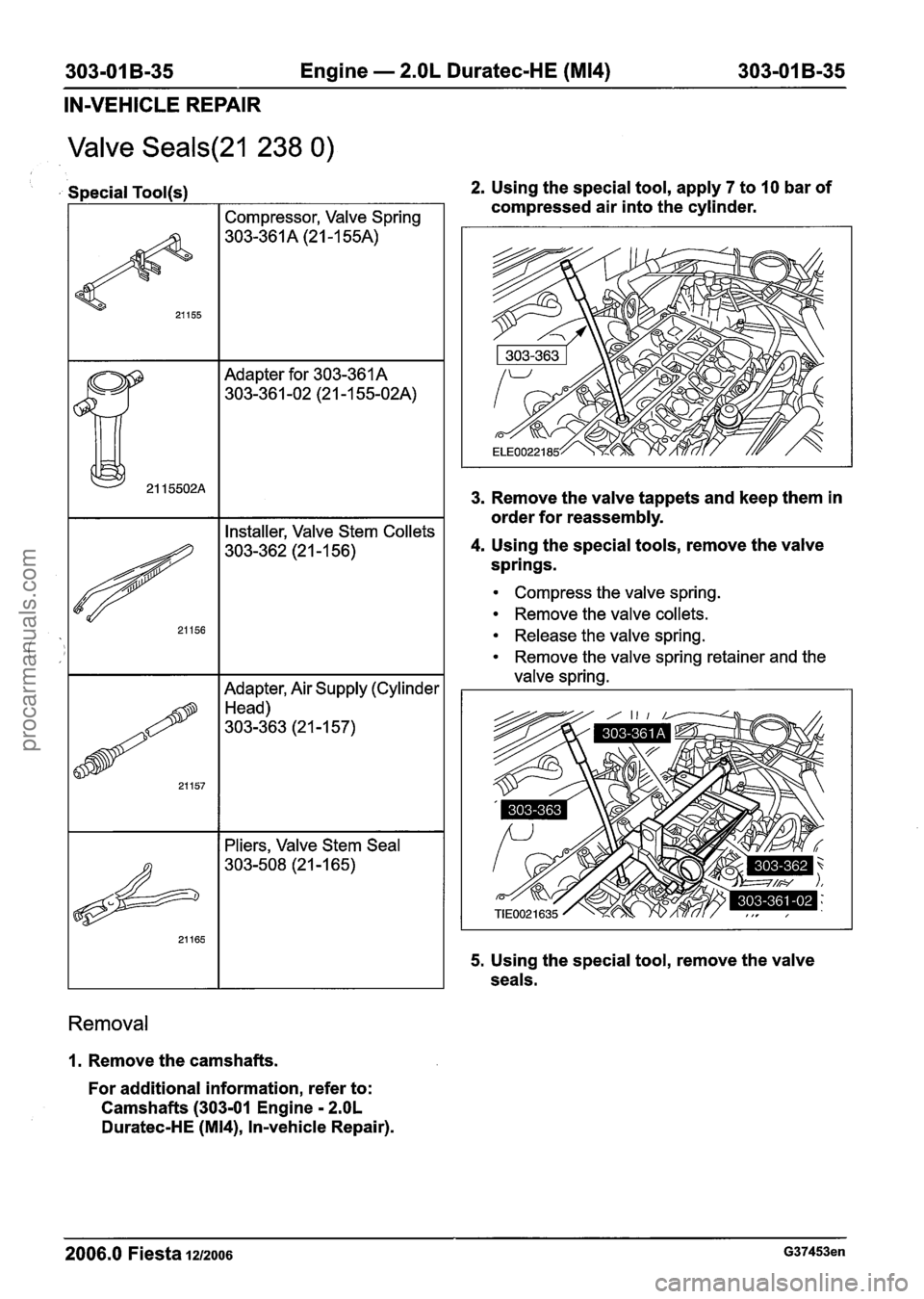
Valve Seals(21 238 0)
Special Tool(s)
I I Compressor, Valve Spring I
Adapter for 303-361 A
303-36 1 -02 (2 1
- 1 55-02A)
Adapter, Air Supply (Cylinder
Head)
303-363 (2
I -1 57)
21157
I I Pliers, Valve Stem Seal
Removal
1. Remove the camshafts.
For additional information, refer to:
Camshafts (303-01 Engine
- 2.OL
Duratec-HE (M14), In-vehicle Repair). 2.
Using the special tool, apply
7 to 10 bar of
compressed air into the cylinder.
3. Remove the valve tappets and keep them in
order for reassembly.
4. Using the special tools, remove the valve
springs.
Compress the valve spring.
Remove the valve collets.
Release the valve spring.
Remove the valve spring retainer and the
valve spring.
5. Using the special tool, remove the valve
seals.
2006.0 Fiesta 1212006 G37453en
procarmanuals.com
Page 658 of 1226
303-01 B-36 Engine - 2.OL Duratec-HE (M14) 303-01 B-36
IN-VEHICLE REPAIR
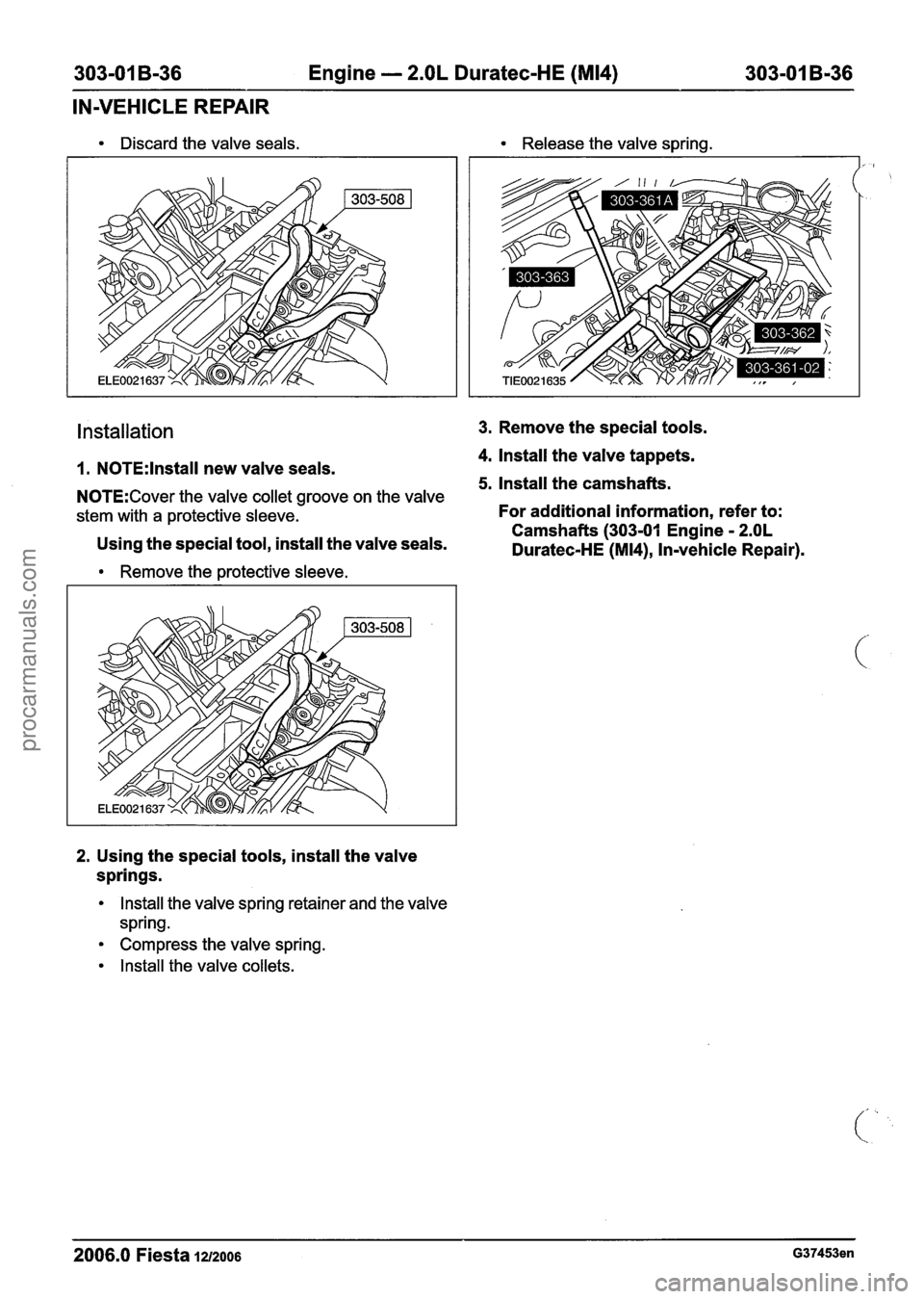
Discard the valve seals. Release the valve spring.
Installation 3. Remove the special tools.
4. lnstall the valve tappets.
1. N0TE:lnstall new valve seals. 5. lnstall the camshafts. N0TE:Cover the valve collet groove on the valve
stem with a protective sleeve. For additional information, refer to:
Camshafts (303-01 Engine
- 2.OL Using the special tool, install the valve seals.
Duratec-HE (M14), In-vehicle Repair).
Remove the protective sleeve.
2. Using the special tools, install the valve
springs.
Install the valve spring retainer and the valve
spring.
Compress the valve spring.
Install the valve collets.
2006.0 Fiesta 1212006 G37453en
procarmanuals.com
Page 659 of 1226
303-01 B-37 Engine - 2.OL Duratec-HE (M14) 303-01 B-37
IN-VEHICLE REPAIR
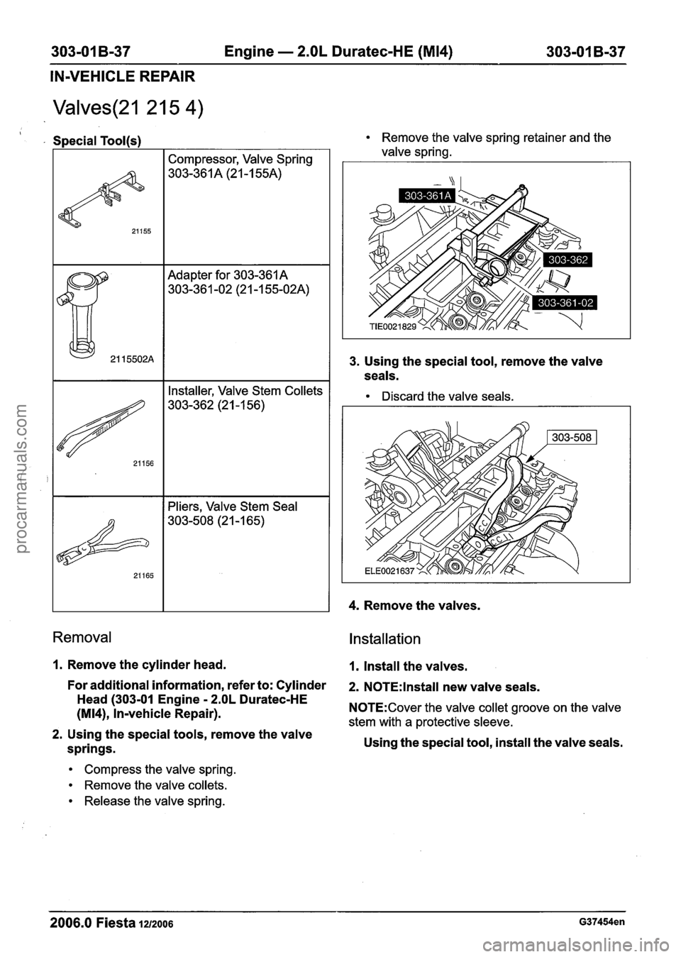
Valves(21 2 1 5 4)
Adapter for 303-361 A
303-361 -02 (2 1-1 55-02A)
Special Tool(s)
I I Pliers, Valve Stem Seal I
21155
Removal
Compressor, Valve Spring
303-361 A (21 -1 55A)
1. Remove the cylinder head.
For additional information, refer to: Cylinder
Head (303-01 Engine
- 2.OL Duratec-HE
(M14), In-vehicle Repair).
2. Using the special tools, remove the valve
springs.
Compress the valve spring.
Remove the valve collets.
Release the valve spring.
Remove the valve spring retainer and the
valve spring.
3. Using the special tool, remove the valve
seals.
Discard the valve seals.
4. Remove the valves.
Installation
1. Install the valves.
2. N0TE:lnstall new valve seals.
N0TE:Cover the valve collet groove on the valve
stem with a protective sleeve.
Using the special tool, install the valve seals.
2006.0 Fiesta 12/2006 G37454en
procarmanuals.com